After taking the dust for a while, i restarted the project:
i knew the stepper was way too weak to animate the arm so i decided to use an old standard servo that i had laying around.
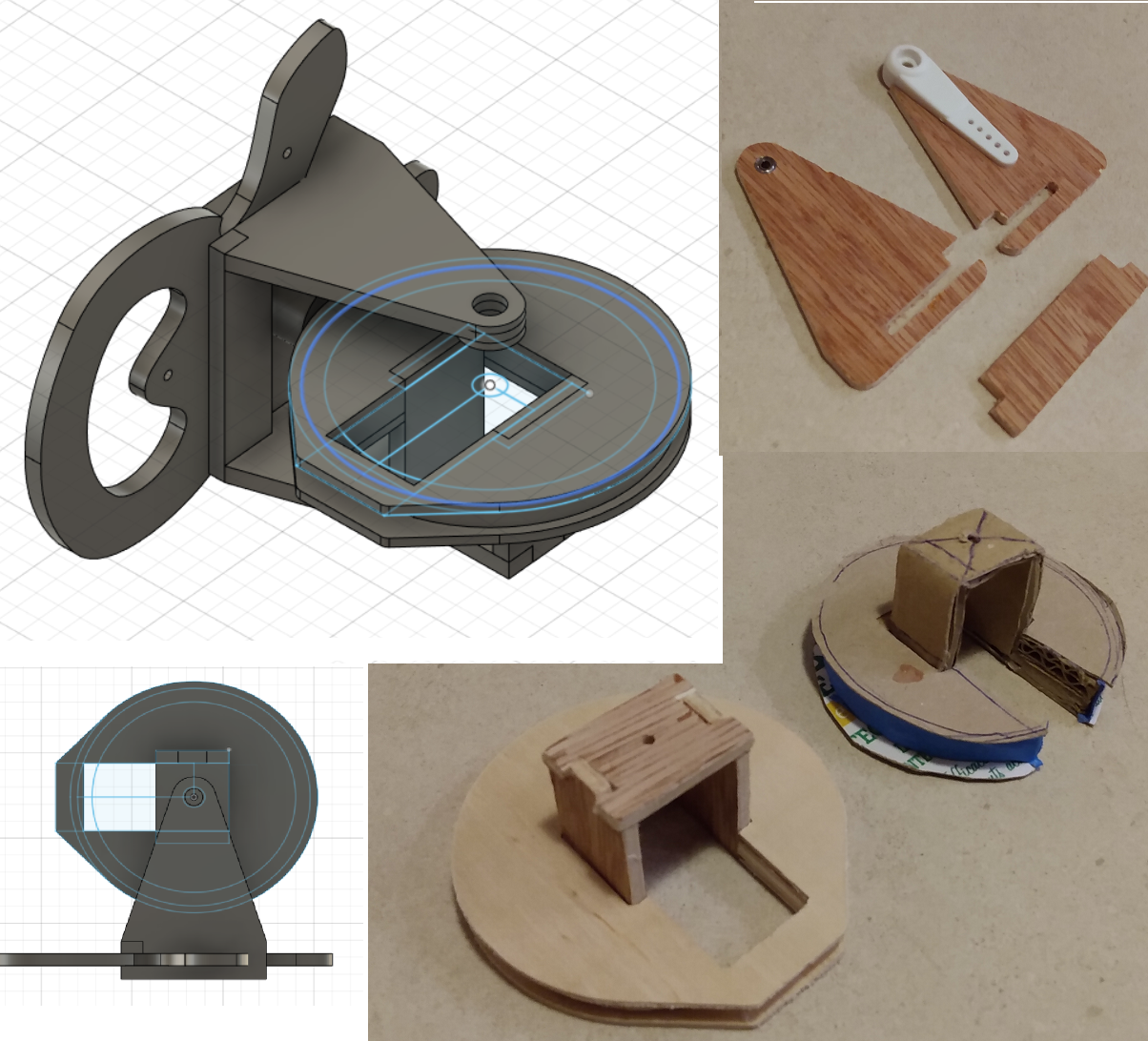
To test the idea, i went through a cardboard prototype again:
Tested the setup with my RC transmitter:
The servo managed to move the arm back and forth with sufficient torque !
So i moved on with the design in fusion 360 and cut the support
Once in place in the lamp base, this plywood support did its job as expected, compared to the cardboard prototype, it did a better job at articulating this arm. However, i realised that i did not had any way of servicing the servo if anything when wrong with it : i had planned to glue everything in place with the lateral "feet" but the assembly was questionable. Back to the drawing board...
This is when i had this long pause in the project because i ran out of ideas...
I managed to get back to it by learning new skills in fusion 360 and putting blender aside :
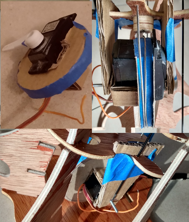
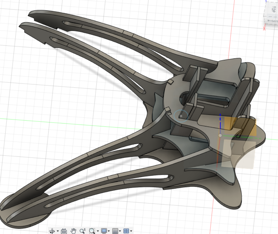
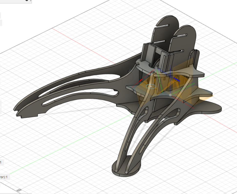
i redesigned the base around a rectangular core (just like skyscrapers) where the arm would slide into place.
The base of the arm would contain the rotary servo assembly that is now secured by four screws
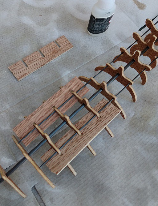
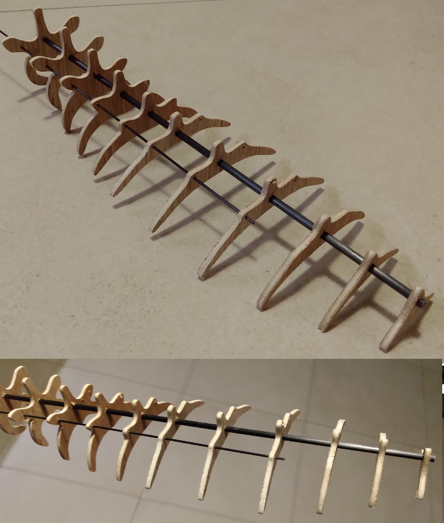
To get a better sense of the rigidity needed for the arm i started to secure the parts together with CA glue:
To achieve an even spacing , i cut 3 spacers that hold the parts before securing them. I did the same on the bike cable for the arm. the lower half has ring supports to increase the contact surface between the cable and the vertebraes. It helps with the twisting and bending.
Turning head
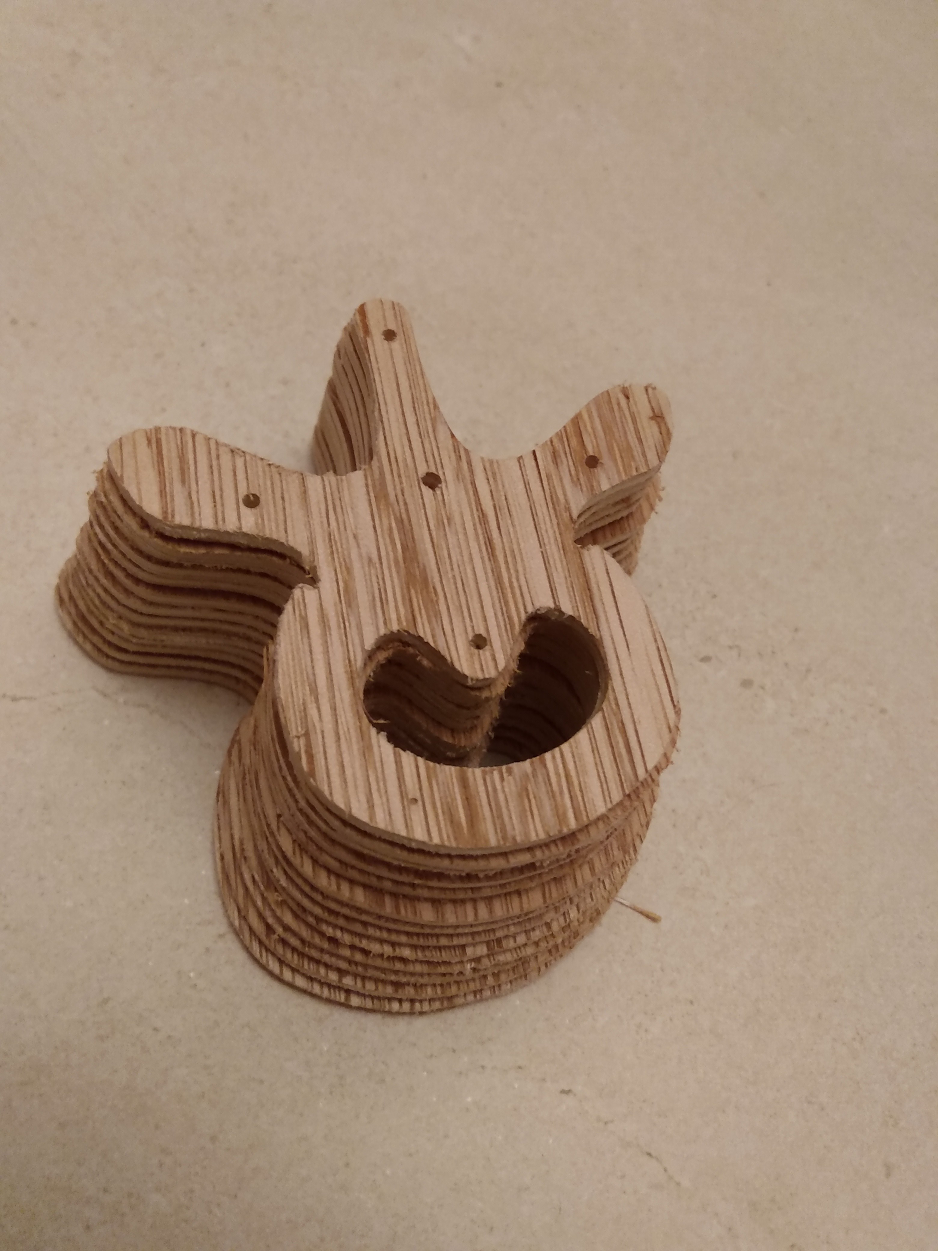
In order to rotate the lamp's head i decided to make my own ball joint. I look what were the commercially available solution but they didn't convinced me. So I stacked several layers of aircraft plywood and assembled them with wood glue to reach a 10mm height. In fusion 360, i modeled 2 half spheres and set 2 passes for the cut. I also cut the housing which is held together with a M2.5 scew and nut. The result is really nice, the texture of the ball surface is a bit rough but helps to keep the joint rigid enough to support the weight of the head
the first motor support i made in the picture above was not rigid enough and all the loads were on the poor stepper shaft.
So i designed another one with the possibility to tension it with a screw and with a support arm in front of the motor that now bear half the load and avoid the pulley torsion. The nice thing is that the mechanism is backdrivable and the arm stays in place , capstan was right, there is a lot of friction in those two cable loops !
The bad new is that the stepper is way too anemic to drive this thing ( and this was confirmed by its datasheet) : i need at least 800g of pulling force on the cable to straighten the arm as above. I'm back to the drawing board for a drive system. I'm trying to reuse some parts i already have and i may try to cut some gears to drive the pulley with a wounded microservo. I don't know if it will be enough and probably won't be backdrivable but i'm out of ideas....
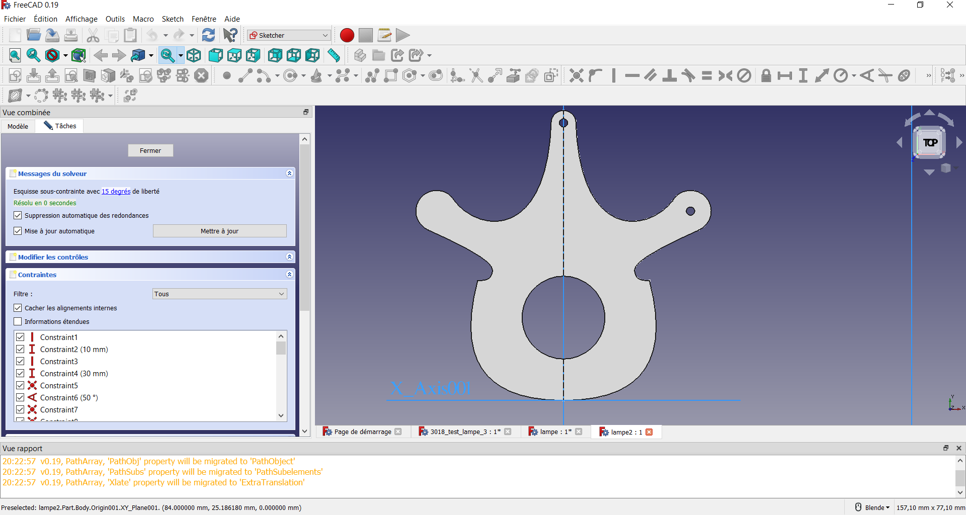
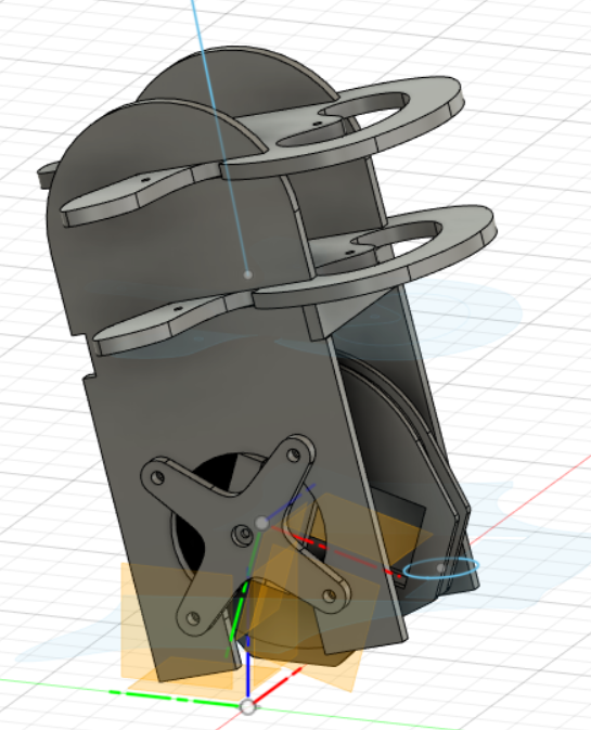
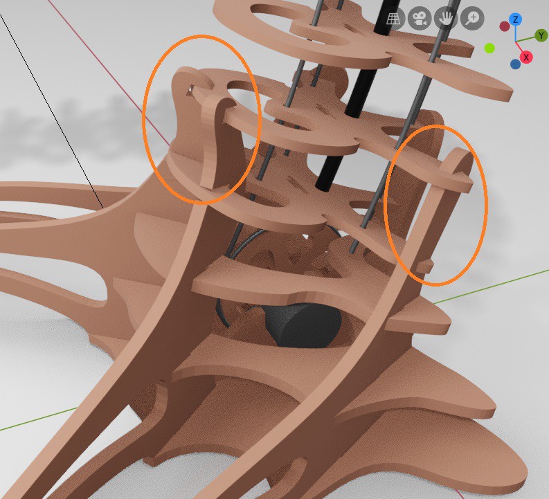
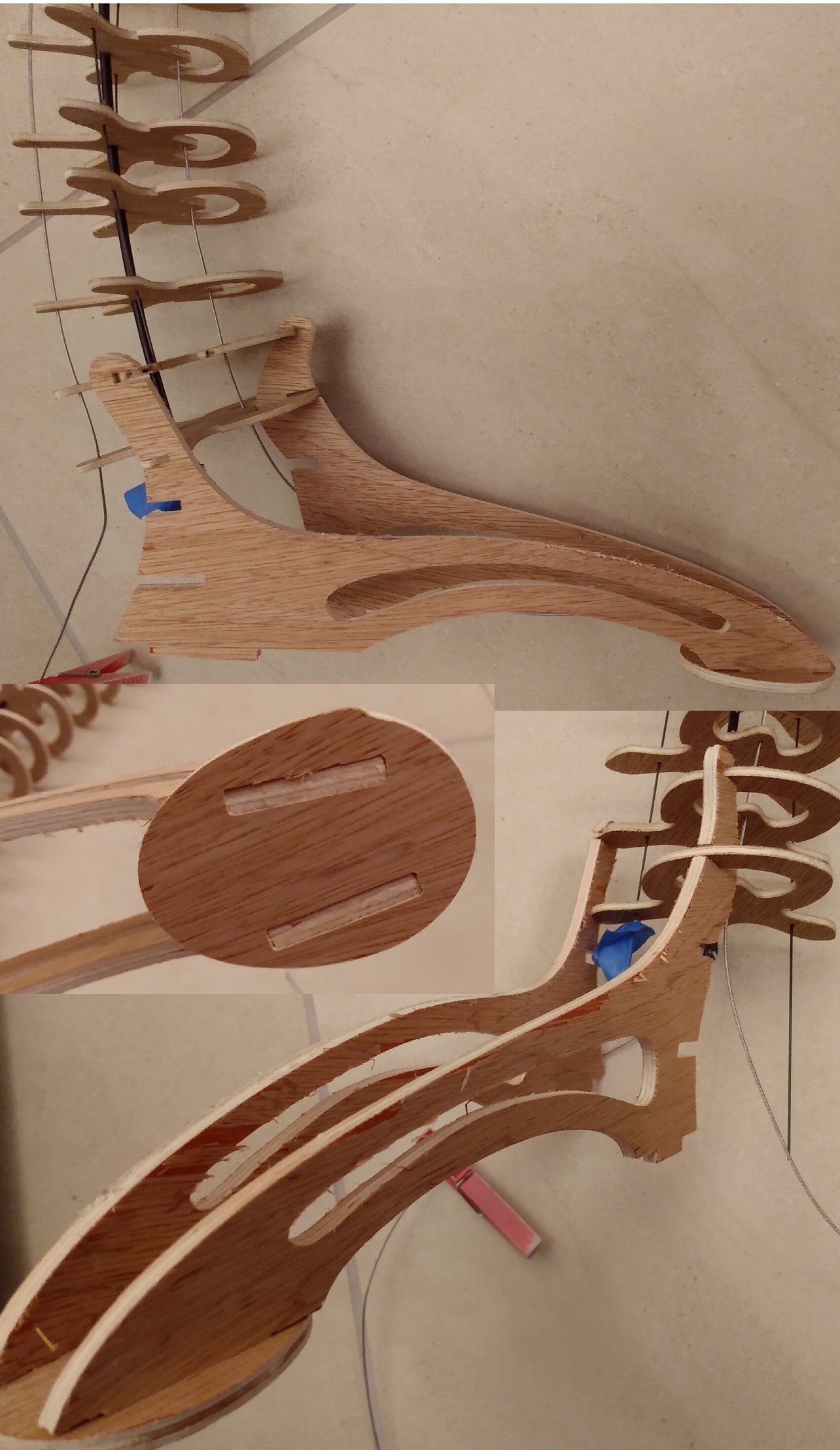
The carboard prototype made me notice that the base of the spine was not rigid enough to support the weight and lever forces acting on the foot. I decided to redesign it a little bit to add a support for a second vertebrae and still have room for the electronics below:
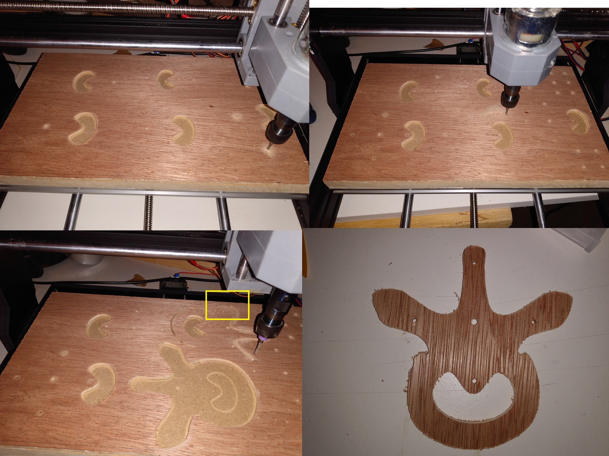
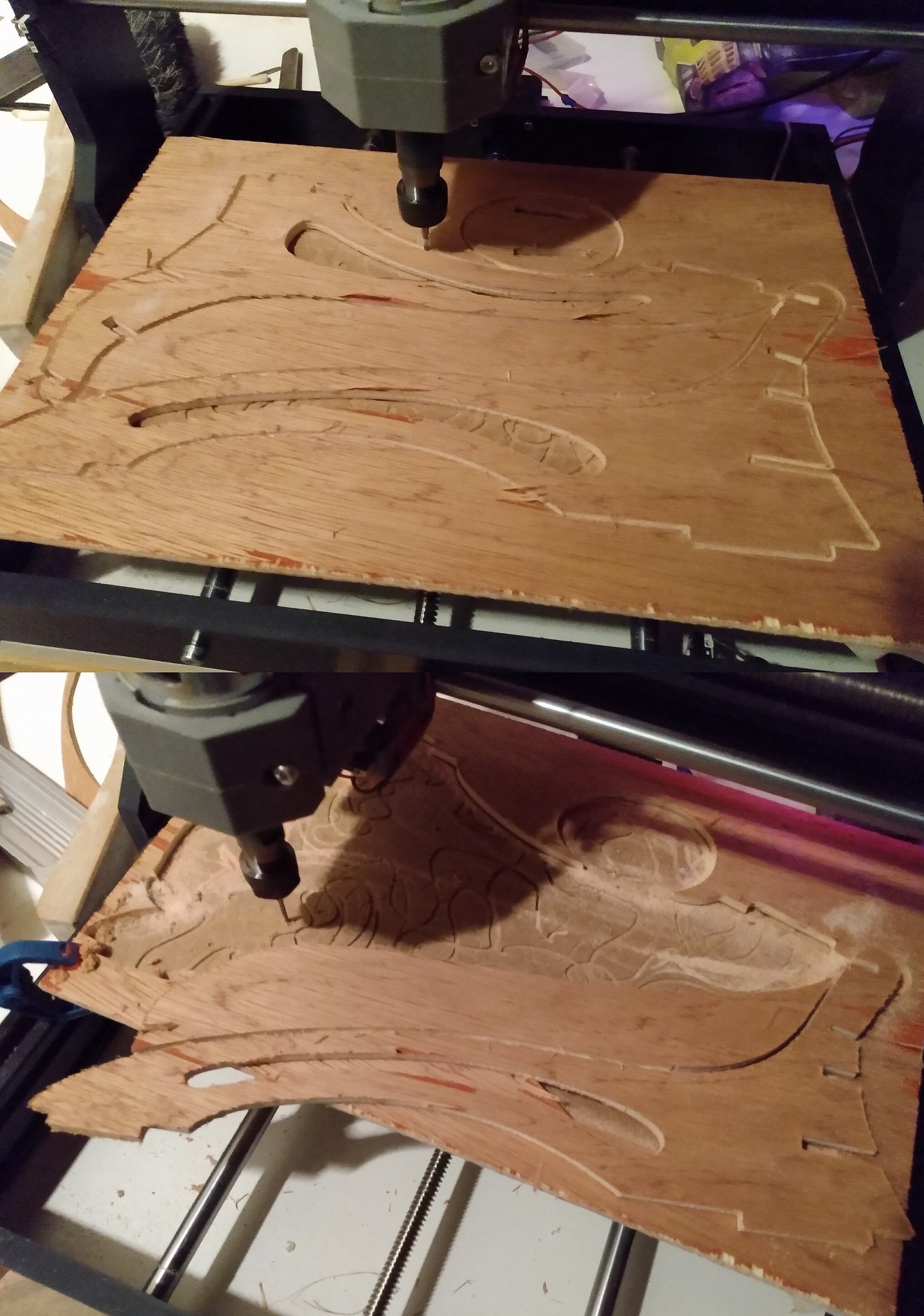
I made the notches in opposition to each other so they could counter the torque of the arm. I struggled to keep these shapes in the available workspace of my 3018 and i had to disable the end switches to gain a few mm of travel. I'm also using 5mm plywood this time (retailer was out of 3.6mm)
Unfortunately, i made another rookie mistake in the cuts set-up : i didn't add any tabs and put the two legs too close too each other, and my part broke off before the end of the path... I managed to salvage the part by cutting the leftover with a handsaw. Another irritating issue is the quality of the plywood i used : that micron-thick plated s..t peels as soons as it is being cut , leaving ugly scorch on the edges...
In the end ,the foot needed a little trim to fit to the tip of the leg but the assembly seems promising! I was really worried by the way it would work in real life, but so far so good. It gives me more confidence in my use of blender for the mechanical design !
Cutting head
I also cut the parts for the head and did another dry assembly to have a feel on its volume :
I think it'll be all right, i still need to figure out how i will link it to the arm... I'd like to have an adjustable articulation between the two to be able to shine the light away from my face if needed. Having this part ready will also help me figure out how much rigidity my arm requires: i bought several carbon rods (1 , 1.5mm and 2mm) and i'm confident that i can find a combination of those that will give the spine its stiffness...
Time for a shitty cardboard prototype to check the soundness of the foot design! After printing the part to scale on paper and cutting out the outlines in carboard, i assembled the minimum number of cutouts for structural integrity: the two arms and two baseplates.
After a bit of tinkering and tape, i managed to get it standing !🤓 I realized that the footprint is a bit large IRL but it seems to provide good enough stability. The constraints on the parts holding the base of the arm looks important , i think i'll have to strenghten a bit this area...
Not quite...
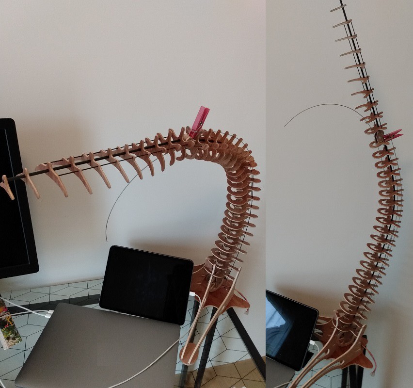
I tried to put it in situation here:
But the overall shape is a bit dissapointing : the stiffness of the central shaft being the same all along the arm, it has a tendency to bend a lot a the base and the final segment is relatively straight. No matter what tension i put on the cable , the bending will decrease toward the tip of the lamp . This is not what the blender render promised me ! 😭 It's the kind of stuff that seems obvious in retrospec, but doesn't appear until you've done the mistake.
What's next?
I need the lamp's head to be high enough ( ideally above my secondary screen) and parallel to the desk's surface..
So a few solutions are available to me:
create a "composite" central shaft with some kind of stiff material at the base and a more flexible one to the top, the main issue is that i already have drillled all the holes in my spines disks.
make a two ( or more ) stages mechanism but the foot might not be roomy enough to hold the actuation part
add some kind of springs with variable stiffness
use an increasing number of carbon rods (and/or with a bigger diameter ) toward the base to increase its stiffness
The last solution seems to be the less demanding in terms of redesign and it might also help with the lateral rigidity ... However the number ,size and location of these rods remain to be determined. I'll need to create the head to account for its weight and dimension the stiffness accordingly. I also need to be careful on the torque needed for the actuation ...
Even if more work needs to be done, i'm really grateful for this piece of garbage prototype, without it, i would probably have wasted a lot of plywood!
As i said previously, i was a bit hesitant on the foot design. The head and the arm part are based on the same technique but i needed some kind of 3d assemblage for the base which need to hold at least the electronics and the stepper... I started some drafts in inkscape but i didn't managed to get satisfying results : i had a hard time visualising the 3d shape i wanted even with the "superposed" interpolation technique...
Change of process
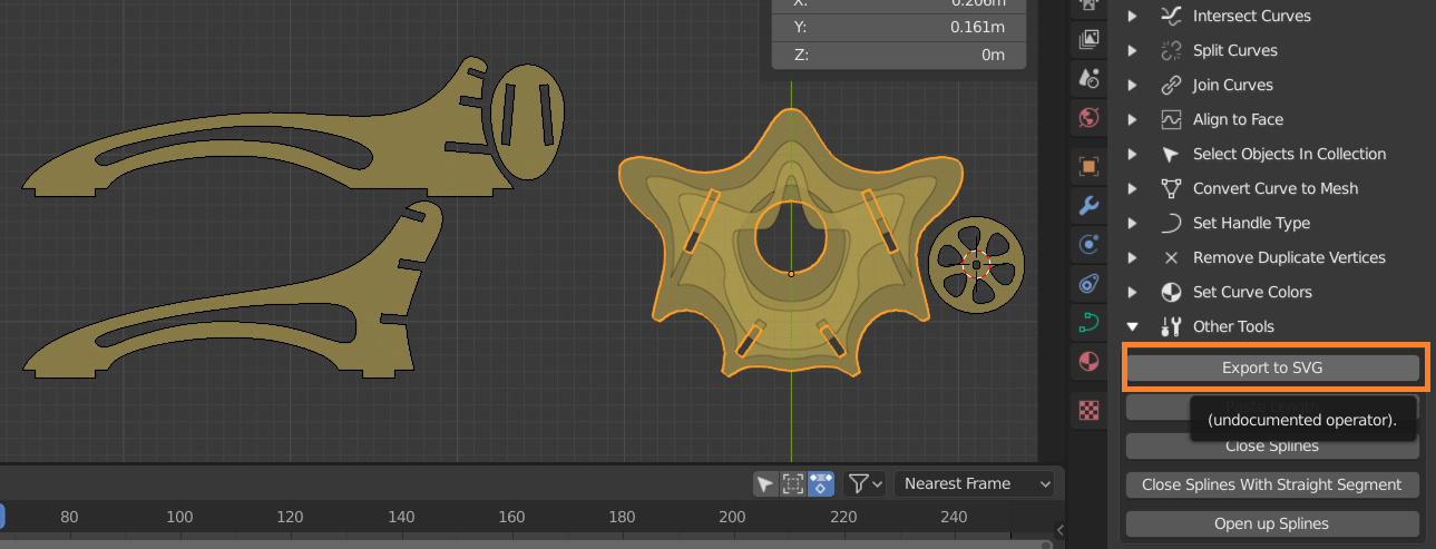
Maaybe i need to do it differently this time : what if i designed my shapes in blender instead? Before trying anything, i had to make sure that i could export them in the familiar SVG format : i found the following blender addon that allows me to export the blender bezier curves as svg https://github.com/Shriinivas/blenderbezierutils I think i'll have to tweak the scale because it exports the shape in viewport pixel coordinates, not a big deal , i'll see later on...
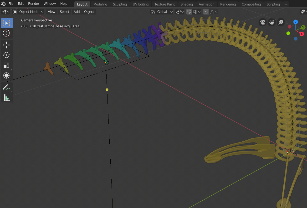
I came up with the same interpolated shape , but this time , they are progressively angled to reach 20°, which is the inclination i find appropriate . The challenge here was to find a way to intersect the legs with those interpolated shapes and assemble them with notches. Earlier in this project i found some software that can do 2 profiles from 3D models but i don't think it would be flexible enough to do what i wanted :https://www.sculpteo.com/en/prepare-your-file-laser-cutting/slicer-fusion-360-tutorial-prepare-your-file-laser-cutting/slice-your-3d-model/ So i decided to do all of them manually, with the advantage of the 3D view to align the notches with one another.
I used the duplicate linked feature which allows to clone a part and move/rotate it in place. When a modification occurs on one part, it is reported immediately on the other one: i have in a corner of my scene all the parts in a 2d plane that i'll be able to export at will. I don't know if fusion 360 or another cad soft can do that less painfully but i already know blender well so...
I also started to find a location for the stepper and the wheel that will control the arm. I still need to find some room to place the wemos and the stepper driver.
I think i will do a cardboard mockup to check the stability and the assembly before cutting any wood.
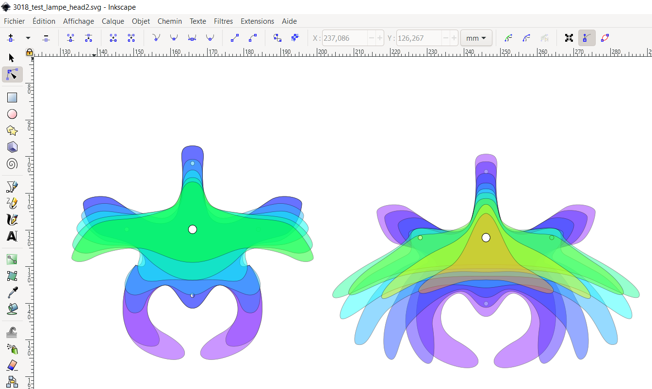
For the lamp head design, i wanted to have a smooth transition between the body and the tip.. I tried to use the "interpolation" functionality of inkscape but it is difficult for the plugin to guess what kind of morphing you want between shapes and it can be done only between shapes with the same number of points.. So i decided to do the morphing manually, by stacking the shape one over another with transparency and different colors: I'm pretty happy with this methodology: i use the center hole that will allow me to glue these parts on a carbon tube as a reference point. Then i can control and correct the morphing between shapes to smoothly evolve them into one another. I did two drafts to see how i could morph into a flatter shape to host the LEDs
Once i was kind of happy with the result , i imported it in blender, offsett each shape by 3cm and solidified them with my 3.6mm plywood thickness.
I also started a foot design but i'm not sure how to link them elegantly to the base of the tentacle... In the render below , i also adjusted the number of vertebraes to match the one i already have... As a result, the lamp has shrinked a little bit... Following the dry assembly, i also figured out that the base of the spine should be tilted by 15° or more: it will move the cg a bit backward and avoid a too big or too heady foot, and the aesthetics and kinematics will be better in my opinion
I also contacted Brian from https://www.poormansguidetoanimatronics.com/ and he kindly reassured me on the soundness of the design and suggested that i should keep an eye on the twisting of the discs around the center shaft. I replaced the lateral cables by piano wires and thin carbon rods and it definitely helped to forbid lateral movement but i still wonder how i will fix the disc on the shaft. I'm also weighting the option of removing the rubber spacer between the disc to have a lighter tentacle....
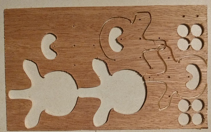
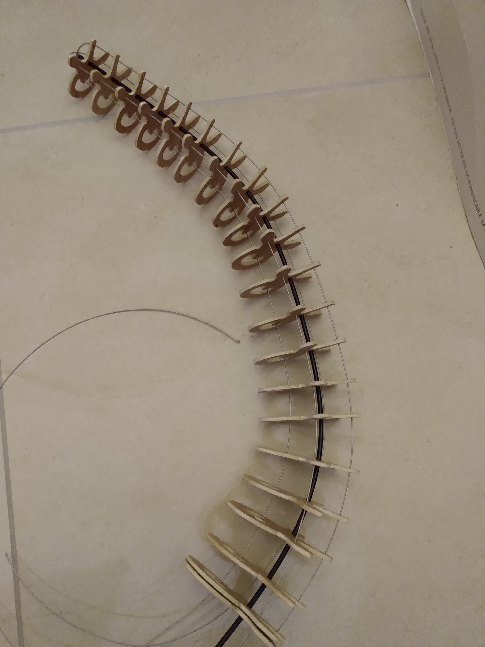
I managed to cut 21 profiles ( in 4 runs on the cnc ) and i couldn't help but try a dry fit with what i had on my hands :) :
the only problem was that i had to re-drill every hole to make the bike shifter cable go though... I also understood why my plywood started to fell off : there is only a micron thick layer glued on every side! I though plywood was made of equally thick layers but this one is plated :( .
i used steel fishing line (rated 63kg, coated in plastic) for the actuation cables it looks lightweight and works well. However i'm wondering how i will turn this bendy, twisty contraption into a sturdy lamp: i expect to have at least a lateral rigidity so i can actuate it only longitudinally . I'm still missing some spacer in between and maybe i will have to glue them to avoid torsion. I'm also thinking of replacing the lateral cables by some thin piano wire to straighten/rigidify . The assembly also suffers from the fact that the bike cable looks permanently bent in some places despite me trying to straighten it with some weight...
here is a test with an addressable led strip in it driven by a wemos and the great https://github.com/FastLED/FastLED library :I don't know if it will make a great lamp but it is a really fun thing to build !
The movements looks really organic:
I will look into what i can do to improve the movements predictability but for now i'm really happy on how it came out !
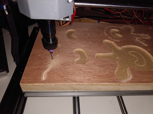
Had the time to cut some more parts today ,but the finish is a little bit rougher:
Maybe the bit start to show wear? anyways , i got 13 out of 25 vertebra done ... What i worry about is the number of spacer i have to cut: 50 meaning that i need to cut 3x50 =150 tiny plywood disk ! i'm not sure that's an effective strategy...
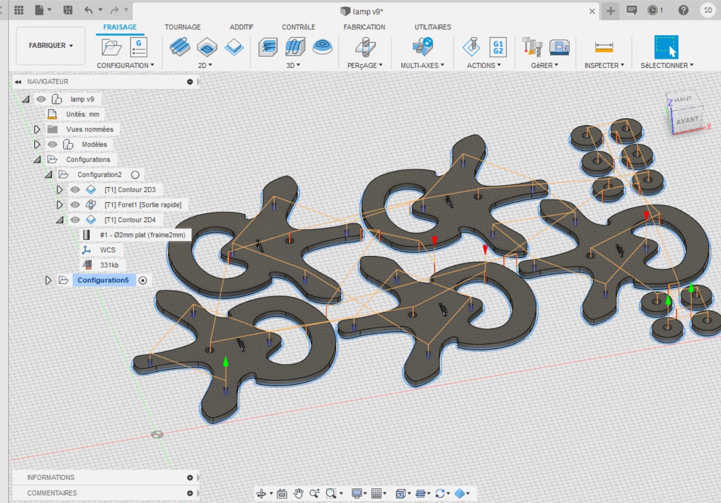
With all due respect for open-source projects, i had a hard time using Freecad v0.18 to do what i wanted... But it helped me a lot to grip the basics notions of CAD and CNCs. So back to fusion 360:
This time, it was much easier to scale things up :
import svg (had to rescale it even if it was defined in mm ,weird)
extrude the shape by clicking on them to match my plywood thickness
create a job
create a 2mm tool
select the edges i wanted to cut in the first pass : all the >2mm holes and create a 2d contour
configure the number of passes ( 2 of 1.8mm each in my case )
run a simulation to see everything running fine
added a drill pass to cut the 2mm cable holes
repeat all the steps 3-7 to add the outside contour cut
post process my gcode file and voila !
Know your limits
So let's fire GRBL candle and plug the cnc : after the origin setup , i send the gcode and start to see the magic :
Unfortunately , things started to go wrong in the last step : the outlines cuts. For some reason , the bit started to go down wayyyy deeper than what i expected: 6mm instead of 1.8 ! After a second of hesitation, i see that the machine still want to cut at this depth, so be it ! I'm so close to having my first part, lets see... yes ! first part finished! it goes to the second one ...Oh no! the upper Y axis limit is hit ! ABORT !
I was way too greedy on the size of my work area : they said 3018 so 30cm x 18cm workspace right? Not quite on my machine :)
Lets do a rescue Gcode to save the remaining profiles :
what? it also hit the X axis limit !?! what a noob !
In the end i managed to get 2 profile out of my first cut, not that bad...
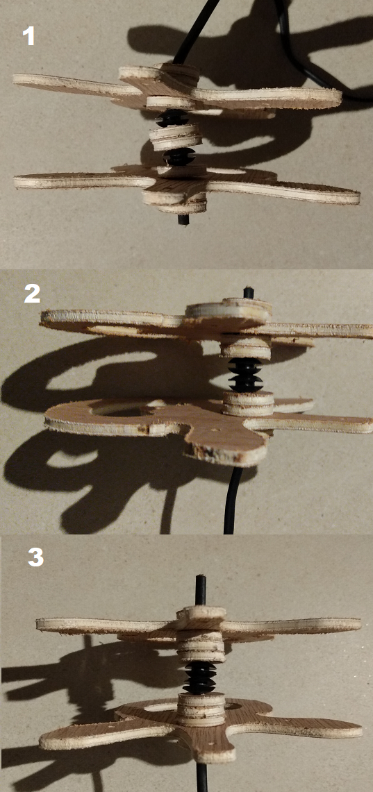
At least it's enough to start testing some assembly schemes :
Number one seems to be too twisty to be usable, number two is okay but with a 27mm spacing, i'd need 37 of them to complete my meter long arm! Maybe i'll go number three with 800mm-ish length /36mm spacing and 22 of them. We'll see...
As soon as this idea popped up in my head , i had to immediately materialize it somewhere. It happens that i've been occasionally using blender for more than 10 year now and i'm familiar with a lot of its shortcut to model objects:: With this first model i totally forgot about the basic principle of the tentacle : it has to have a central shaft to be articulated! Plus the spines are upside down, and the spine profile lacks in details, but at least it gave me an idea of how it could look...
To freecad...
So how do i translate this into a physical thing i can (automatically) manufacture?
Looks like i need a CAD software! How about freecad? I followed the first tutorial https://wiki.freecadweb.org/Tutorials and it seemed very powerful at first :
But thing were a bit complicated on the bezier side: so much things on the toolbar ! Do i need to constrain all the things ? how can i constrain handles? What are those green stuff displayed everywhere? seems to indicate the stiffness of the curve or something...
To Inkscape...
So i decided to work bezier curves with inkscape instead on which i'm much more familiar. After a quick svg import, i managed to generate a tool path for my snowflake and run a simulation , nice !
so i think i can scale this process to get my 24-ish plywood pieces for the lamp! Lets try it ,model everything in inkscape :
and then import it in freecad :
Starting from here things get complicated, for some reason , when i try to convert these shapes to sketches, the axis are inverted , i cannot remember the process to make the holes , i need to get back to the tutorial... Same for the toolpath, i have trouble selecting the shapes i want to cut, i dont understand where my tools are saved ...
 Tested the setup with my RC transmitter:
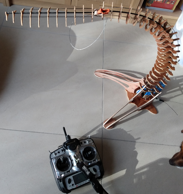
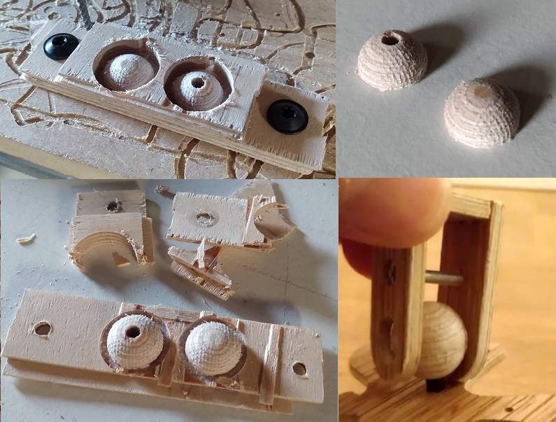 The result is really nice, the texture of the ball surface is a bit rough but helps to keep the joint rigid enough to support the weight of the head
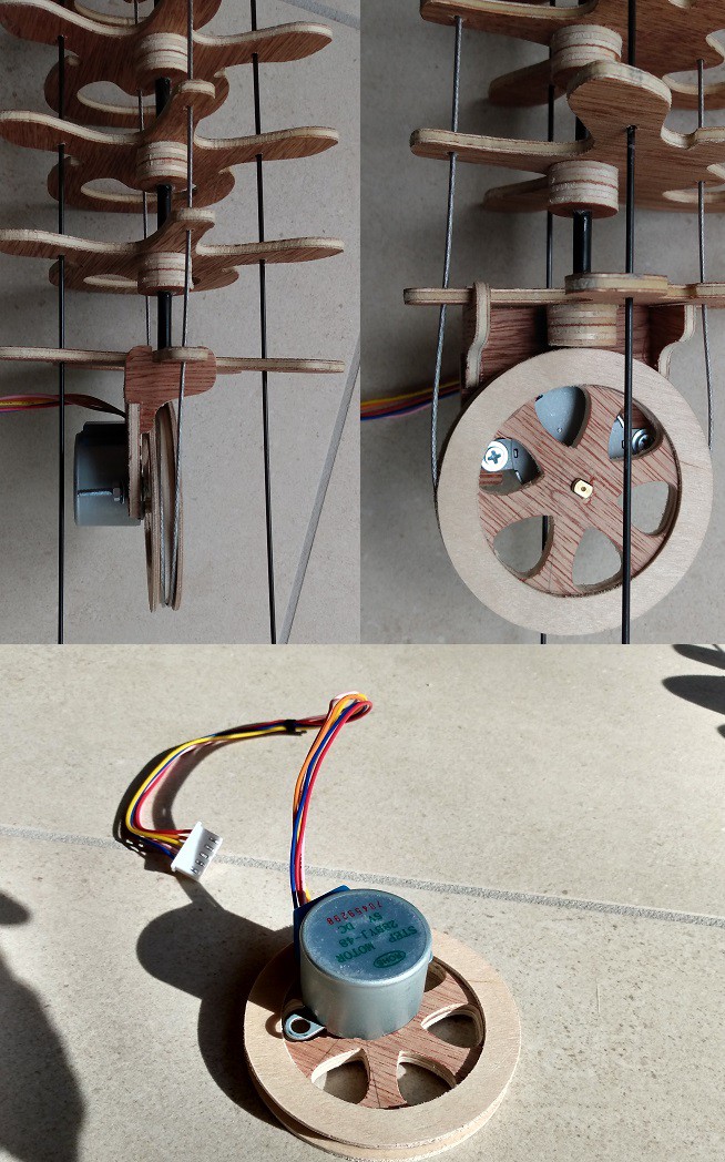 the first motor support i made in the picture above was not rigid enough and all the loads were on the poor stepper shaft.
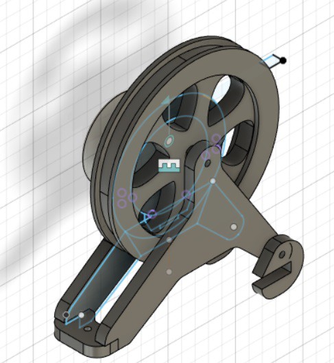
 I think it'll be all right, i still need to figure out how i will link it to the arm... I'd like to have an adjustable articulation between the two to be able to shine the light away from my face if needed. Having this part ready will also help me figure out how much rigidity my arm requires: i bought several carbon rods (1 , 1.5mm and 2mm) and i'm confident that i can find a combination of those that will give the spine its stiffness...
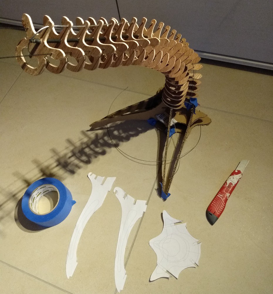 After a bit of tinkering and tape, i managed to get it standing !🤓
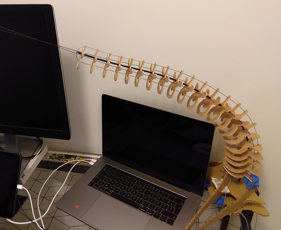 But the overall shape is a bit dissapointing : the stiffness of the central shaft being the same all along the arm, it has a tendency to bend a lot a the base and the final segment is relatively straight. No matter what tension i put on the cable , the bending will decrease toward the tip of the lamp .
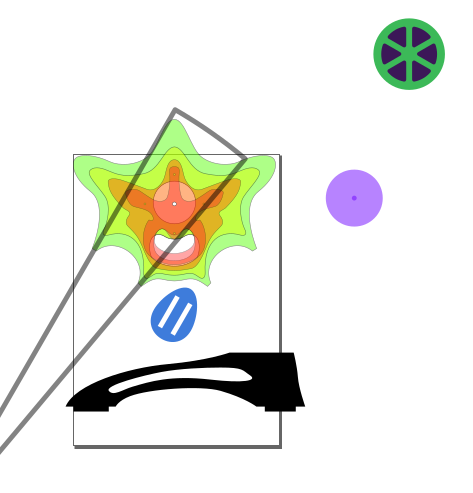
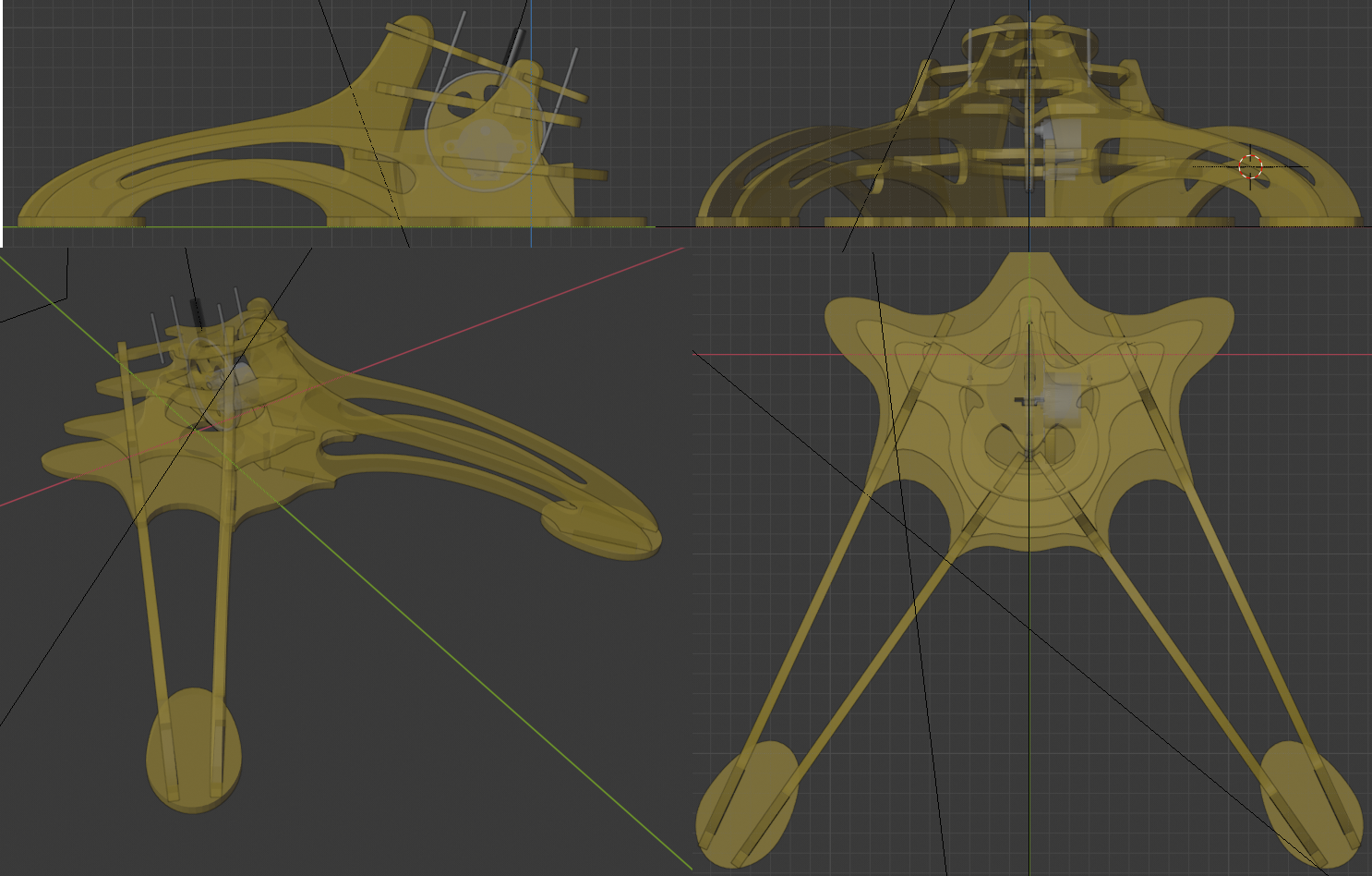
 I used the duplicate linked feature which allows to clone a part and move/rotate it in place. When a modification occurs on one part, it is reported immediately on the other one: i have in a corner of my scene all the parts in a 2d plane that i'll be able to export at will. I don't know if fusion 360 or another cad soft can do that less painfully but i already know blender well so...
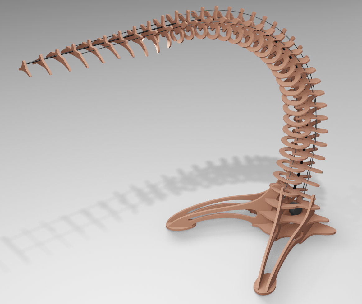
 I'm pretty happy with this methodology: i use the center hole that will allow me to glue these parts on a carbon tube as a reference point. Then i can control and correct the morphing between shapes to smoothly evolve them into one another.
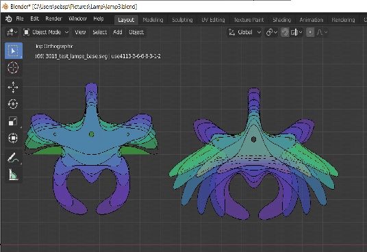
 I also started a foot design but i'm not sure how to link them elegantly to the base of the tentacle...
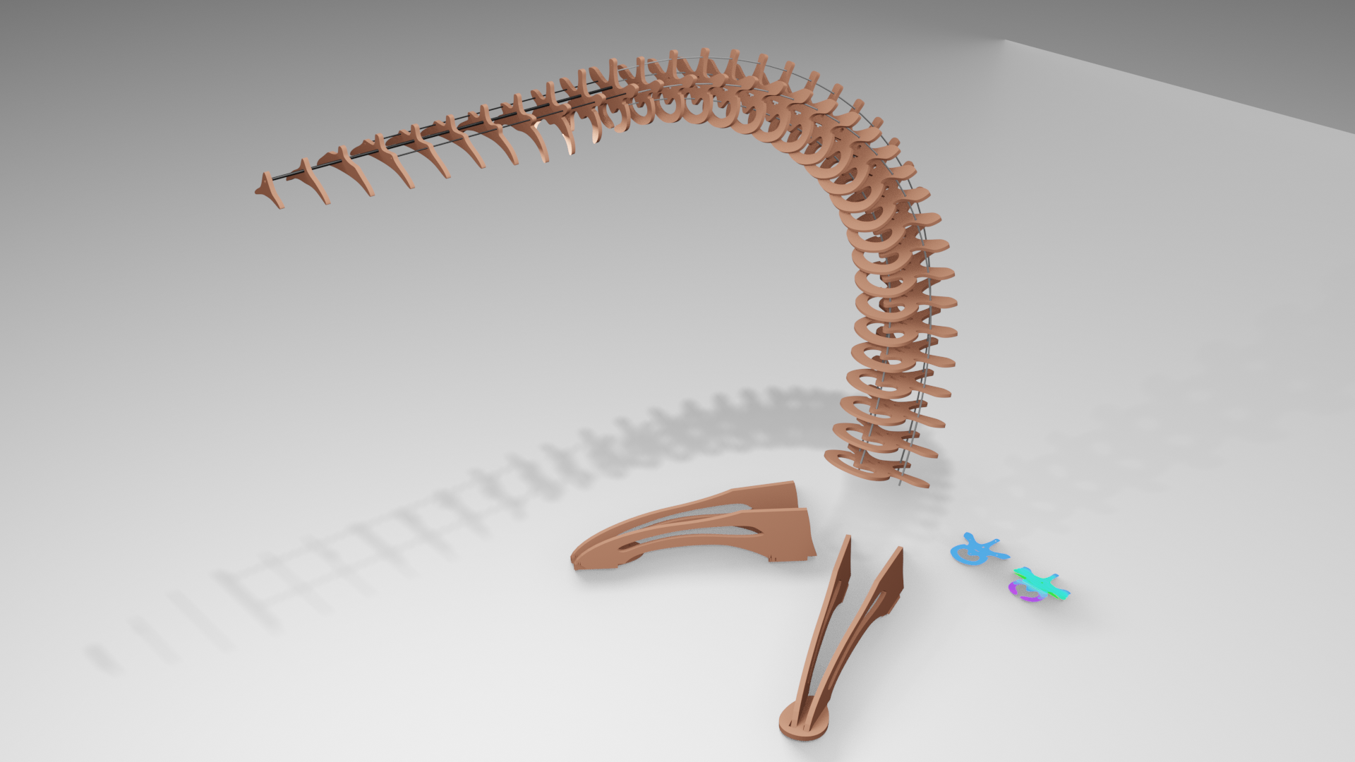
 the only problem was that i had to re-drill every hole to make the bike shifter cable go though... I also understood why my plywood started to fell off : there is only a micron thick layer glued on every side! I though plywood was made of equally thick layers but this one is plated :( .
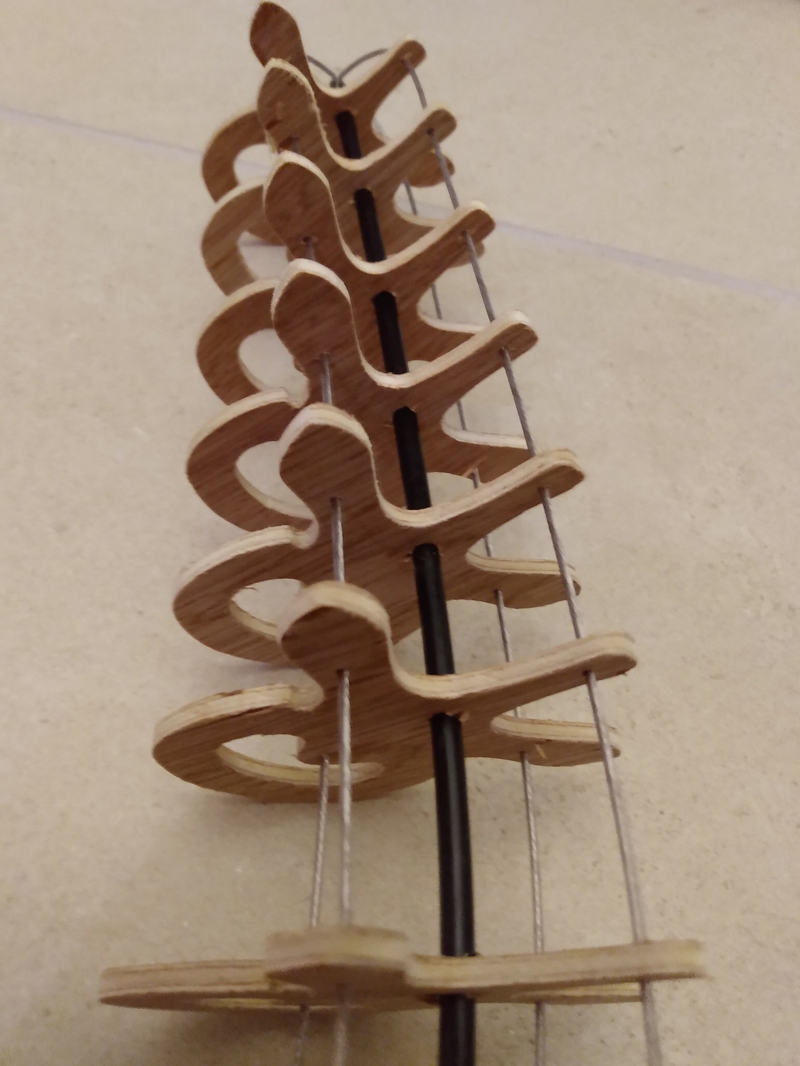 i used steel fishing line (rated 63kg, coated in plastic) for the actuation cables it looks lightweight and works well.
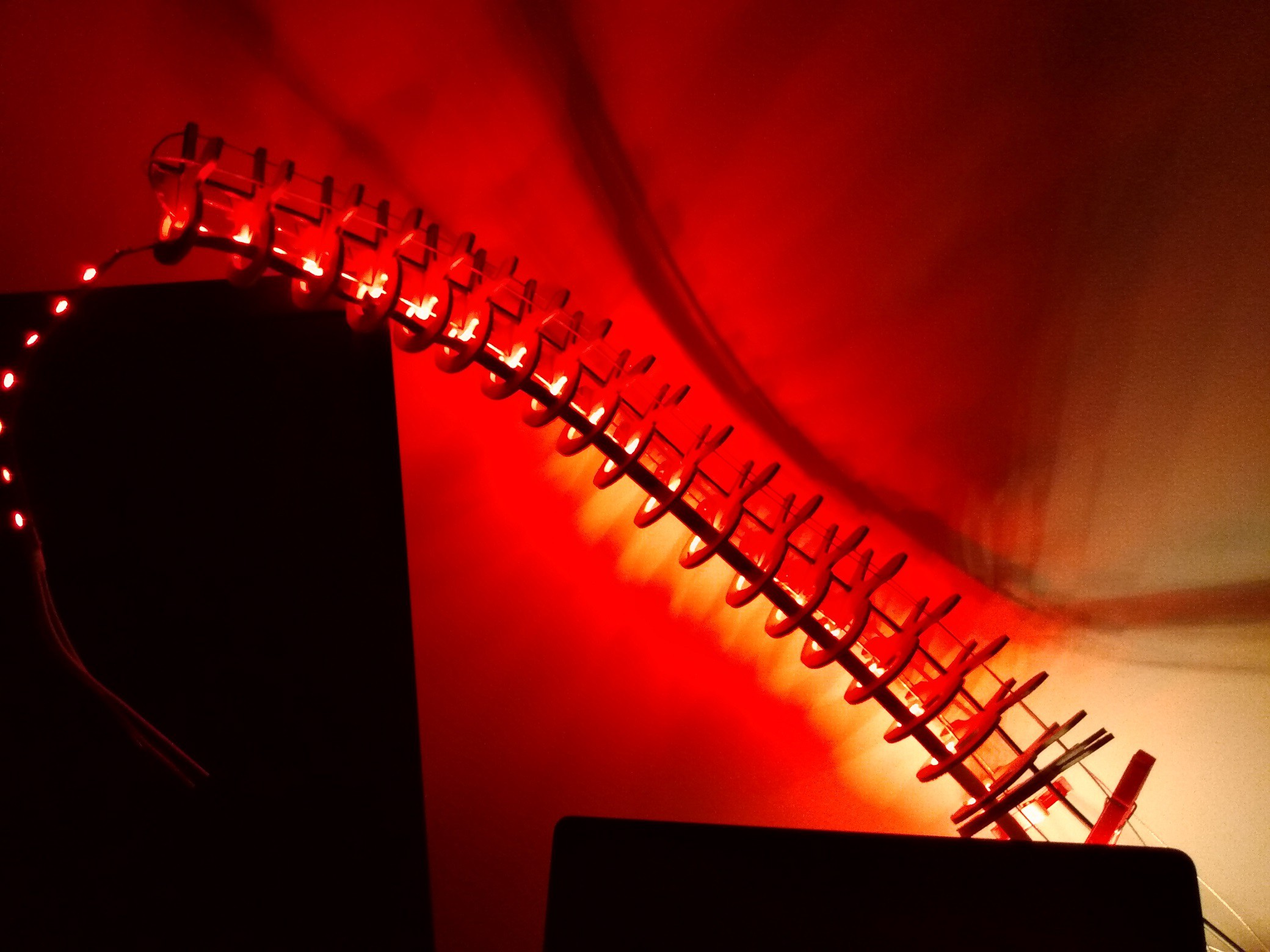 I don't know if it will make a great lamp but it is a really fun thing to build !
  I will look into what i can do to improve the movements predictability but for now i'm really happy on how it came out !