-
Running FOC mode
11/01/2021 at 03:55 • 0 comments -
500W PSU
10/22/2021 at 00:50 • 0 comments500W PC PSU gives much better distribution.
![]()
-
First LED test
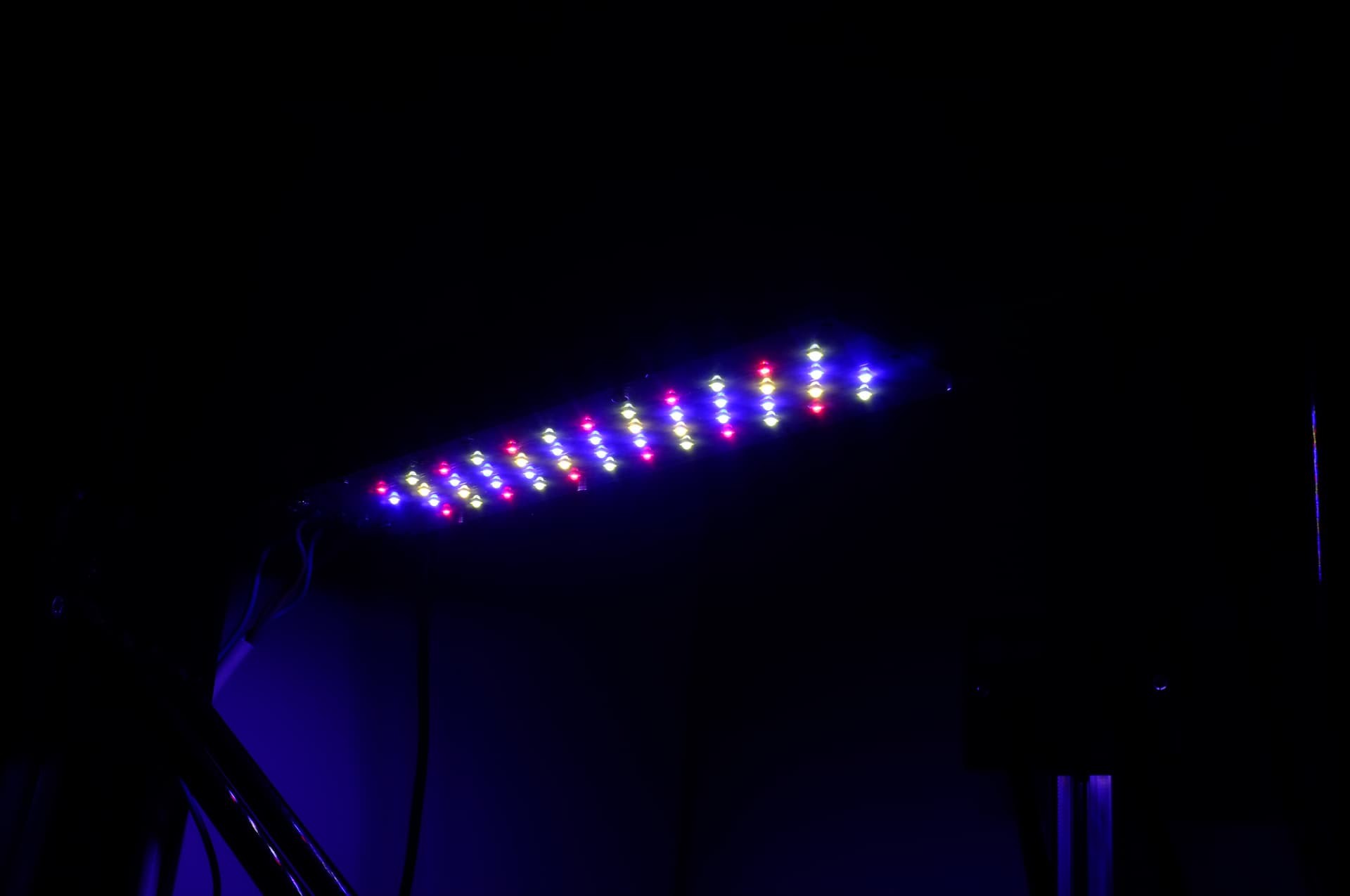
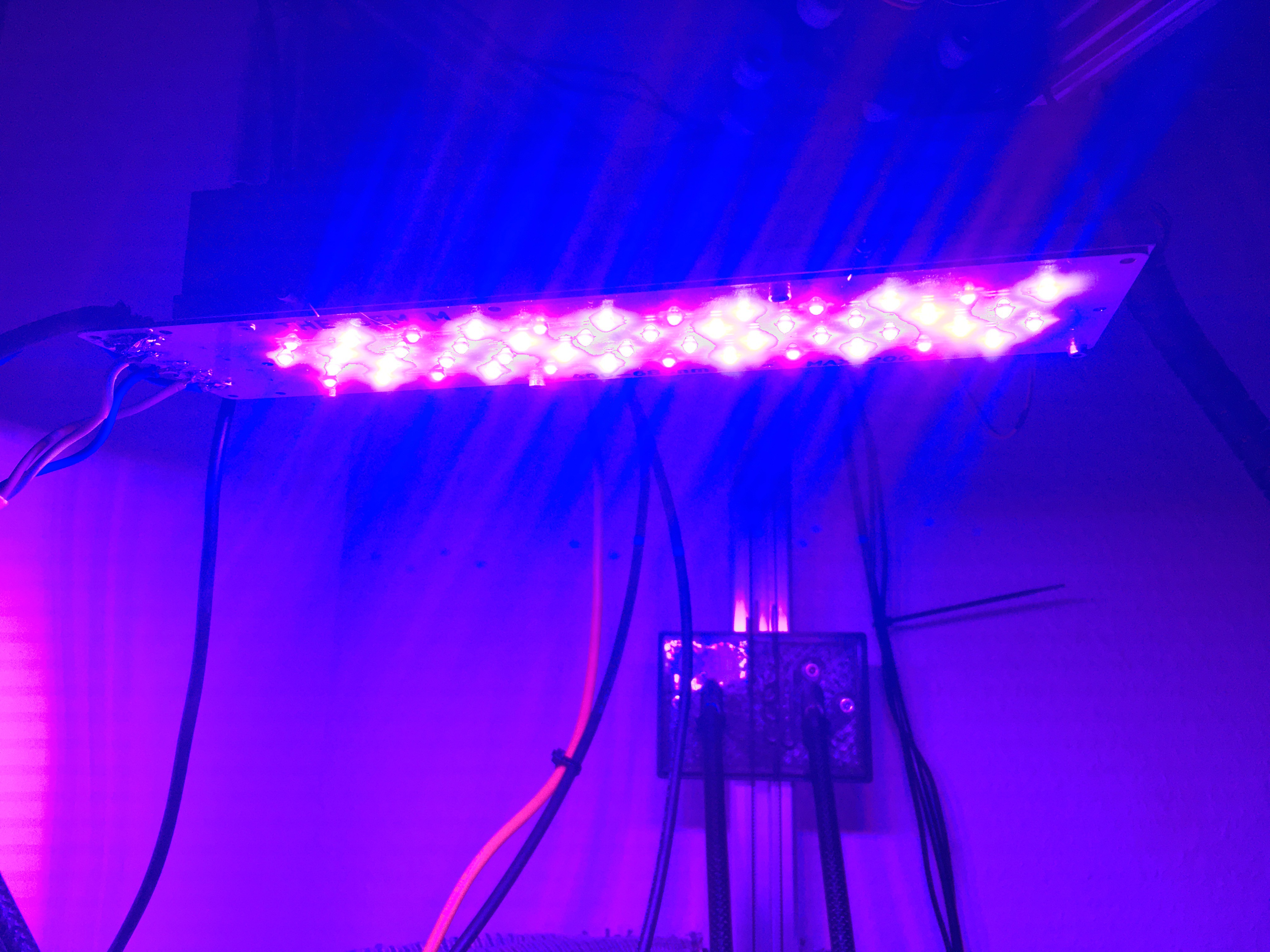
10/20/2021 at 06:05 • 0 commentsFinally, the time came to power up those high current led´s.
The LED´s does work as expected, even without a current limiting resistor. Using PWM controlled half-bridges the intensity can be adjusted.
At the very lowest setting, it is possible to look at the LED´s, but just turning up the PWM a bit makes the lamp to bright to look at.
At high intensity there is significant heat development, so my original approach seems to hold true.
-
HALLOWWORLD
10/17/2021 at 15:58 • 0 comments -
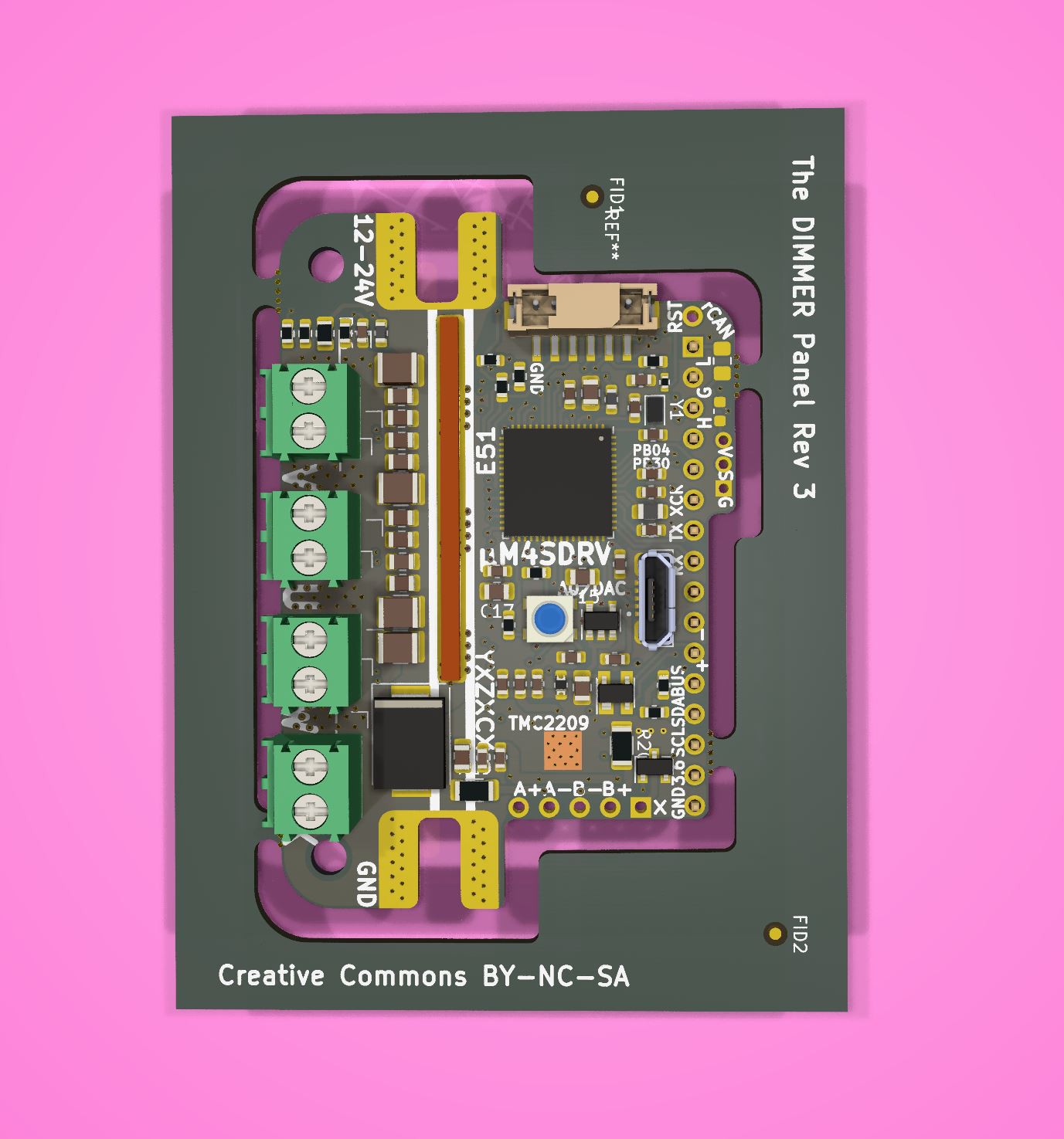
REv 3 (Now 3 phase bldc driver w. brake resistor port)
06/13/2021 at 20:27 • 0 comments -
The Dimmer Design Done
04/22/2021 at 16:41 • 0 commentsThe controller is now ready for testing. Have had to do a few changes to insure good system reliability.
* Since the controller can be used as a BLDC or stepper controller, I have upgraded the TVS diode package.
* The 5V LDO have been upgraded to MSOP8 packgate (500mA continuus) from SOT 23-5 (only 200mA continuus).
* Screw terminals has been upgraded to 3.5 pitch, which has a 17.5amp rating, thats 35 amp per phase (Continuus). Each terminal is rated to carry two conductors. This means 4 separate LED modules w. 4 channels can be powered/dimmed from a single controller. Do note that each half bridge is 60 amp rated. I would under no circumstance recommend to go beyond 1000WATT because of switching loss´s (depending on switching freq. and passive or active cooling).
* Main power wire lugs has been upgraded to 85 amp rated from 65 amp rated. Do note that the lugs will get hot at 85 amp. The 65 amp lug can still be used. Wires can also be soldered directly on to the board, eg. if the controller should be integrated into a CNC routed heatsink/housing.
* Microchip (ATSAME51 MCU producer) advises to use a ferrite bead in series with the analog power domain supply, for some applications. This is to filter out digital noise before it hits the ADC/DAC. So I have chosen to follow their advice. The bead should be carefully chosen for DC filtering w. lowest possible resistance.
* Moved the 3 analog hall sensors, so that all 3 is aligned to center of rotation for NEMA23. For bigger steppers a 3D printed bracket can be used.
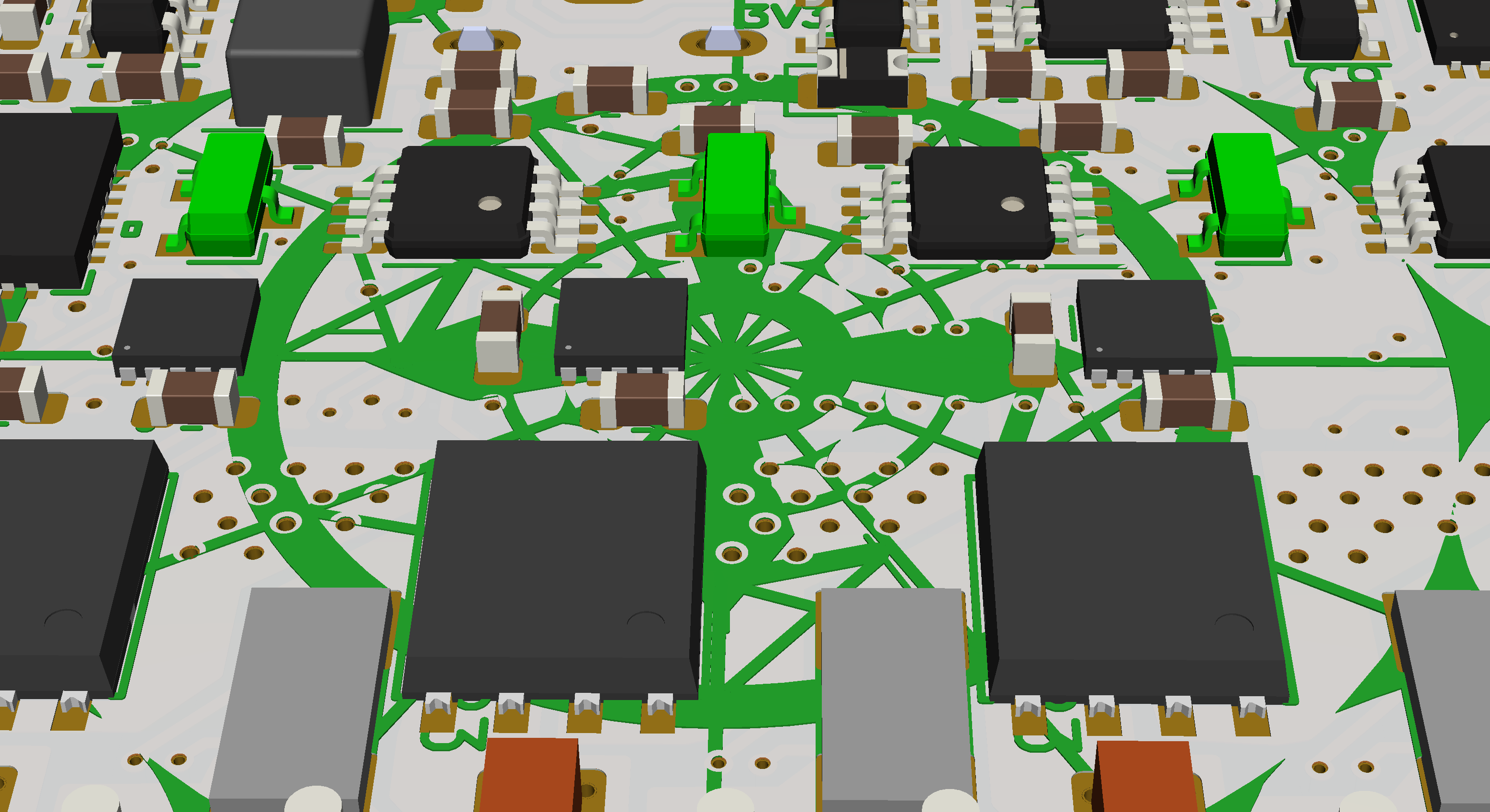
The 3 hall sensors highlighted in green placed to cover 30 degrees. The ADC (Analog to digital converter) of the SAME51 can make 1.000.000 samples per second. The MCU has two seperate ADC´s of which ADC0 is used for on board measurements (Not including A0/DAC which is broken out) Two pins on ADC1 is broken out for external use. Pin functionality will be mapped in code. Broken out pins can also be regular IO/EXTINT.
-
IAUC60N04S6L030H
03/28/2021 at 12:24 • 0 commentsIAUC60N04S6L030H
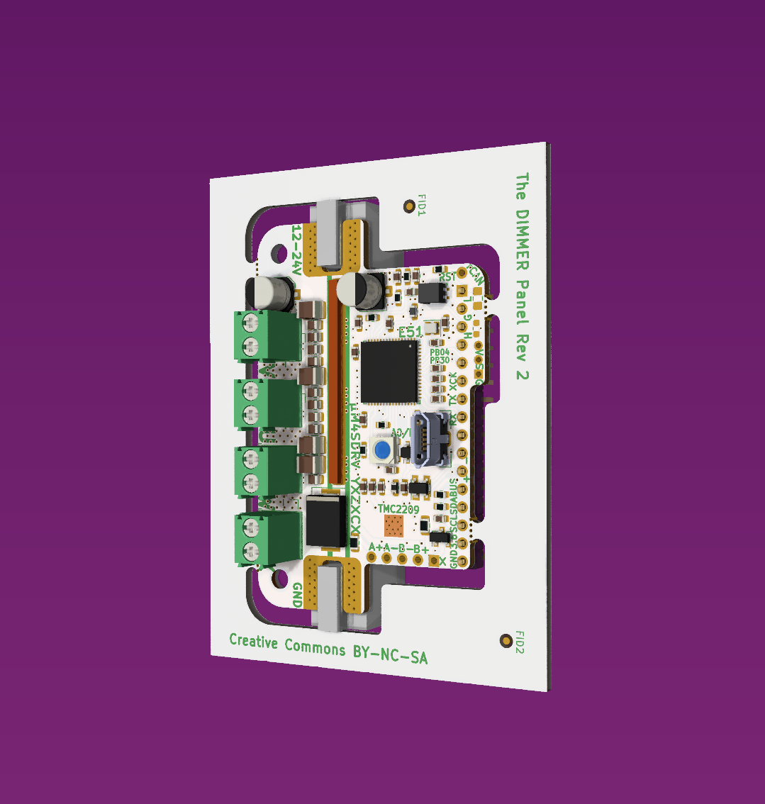
Rev 2 Last minute change; upgraded to 40 V rated Bridges. Downgraded Sense resistor from 3W to 2W 2010 package.
-
Magnetic Decoder
03/28/2021 at 00:53 • 0 comments![]()
-
REV_2
03/26/2021 at 13:48 • 0 comments -
XP_G3_1Cj/W
03/14/2021 at 18:33 • 0 comments
 Juan-Antonio Søren E.P.