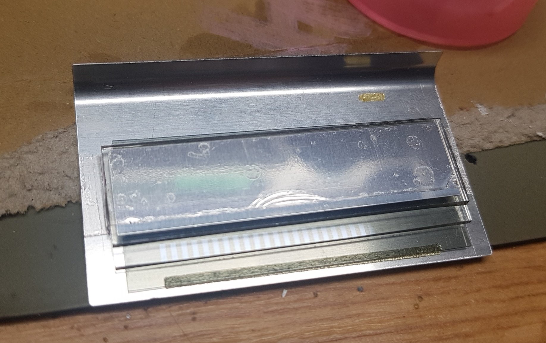
This is a super clickbaity title, since I don't have anything to show yet. But I will set my case of why I think it's doable. First off something weird that you might miss when taking it apart: the black cover has a polarising filter glued to it, which you need to see any change on the LCD. The cable that is connecting the PCB and the LCD will most likely not stick to your LCD anymore. In the picture below you can see the shadow thrown by the sticky glue that was supposed to hold the cable to the contacts on the LCD between the glue. There's a frame holding the display in place.
With a bit of help by WD-40 you can sulk the glue and later remove the residue with a q-tip. The WD-40 needs to be removed as well, best to use some alcohol I guess. In the picture below you can see the pads on glass very nicely. Now you can't solder to these pads, but you might know that zebra silicone strips exist, that only conduct in one direction.
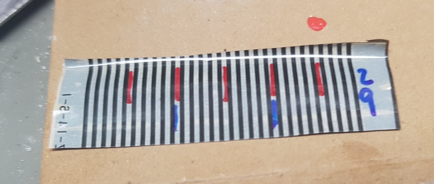
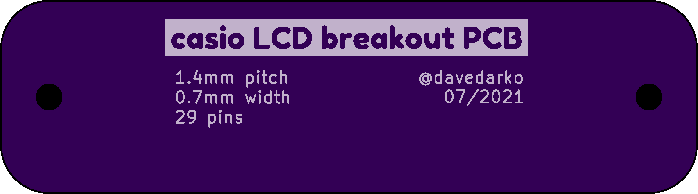
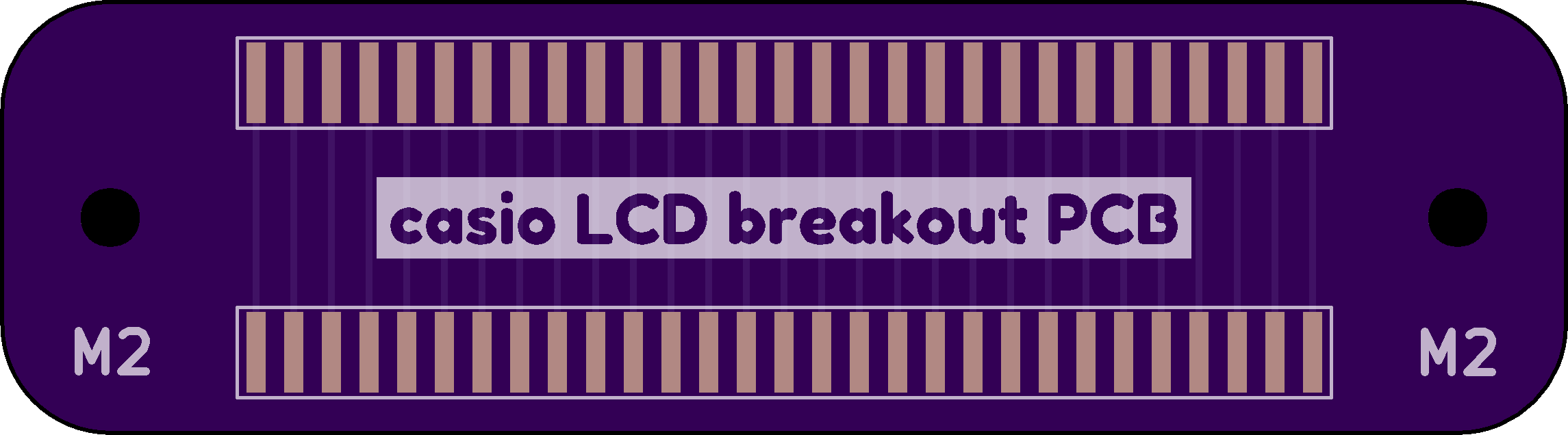
Down below you can see a piece of the cable that I've cut with some scissors. It has 29 tracks / wires and the display is grouped in segment triplets - so there are 3 x 26 = 78 segments on that LCD. - 8x 7-segments
- 8x '#' = 64
- 8x decimal point
- 5x calculator related segments
- beat indicator
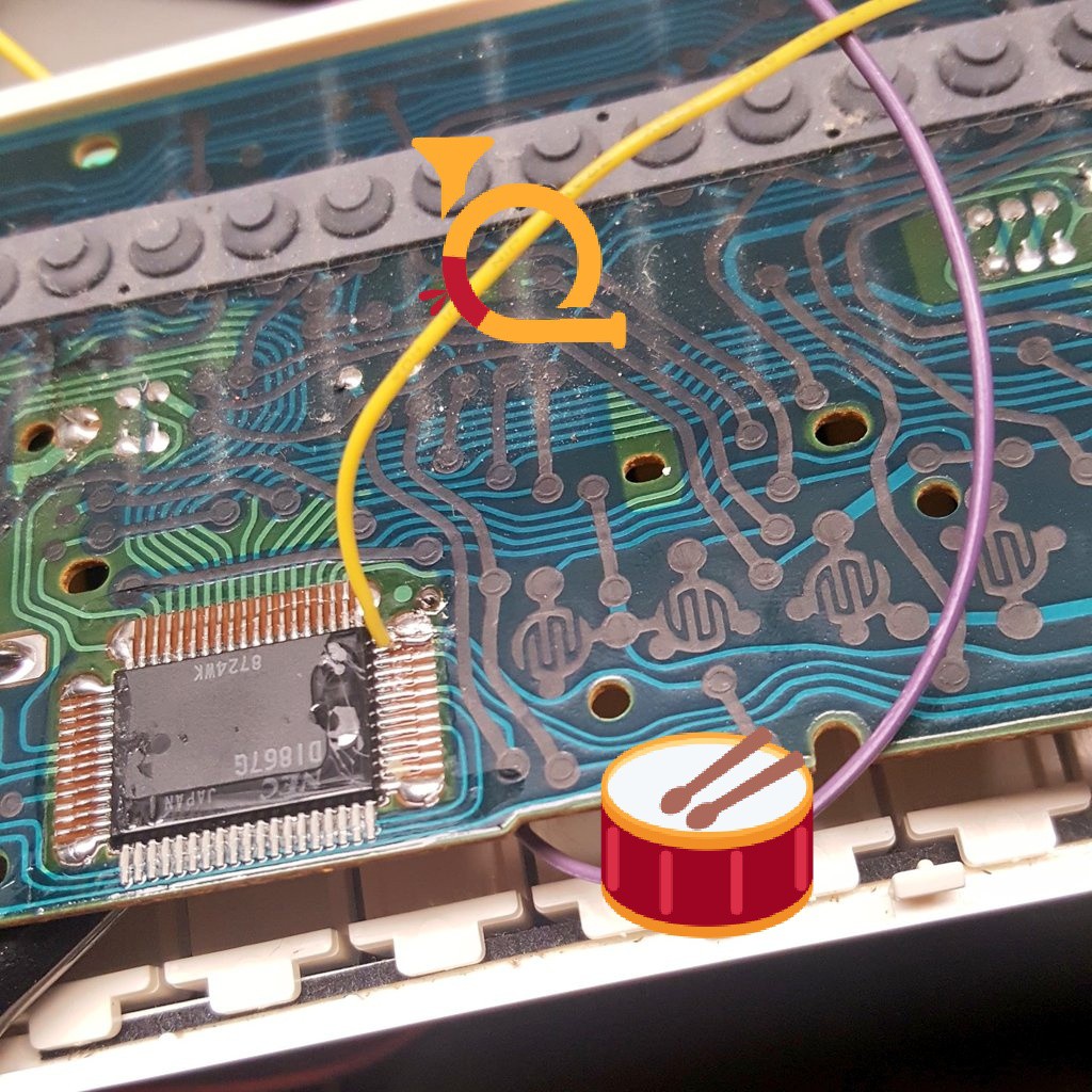
Since these pins are also on any other Keyboard and there's a segment that blinks in the speed of the rhythm, this is of interest to people that want to modify their D1867G based keyboard.
I've ordered five zebra strip with the length of 5cm for less than 10 Euros. With the right size, the help of some 3D printing and a small PCB design this should be fixable. PCB is designed and ordered.
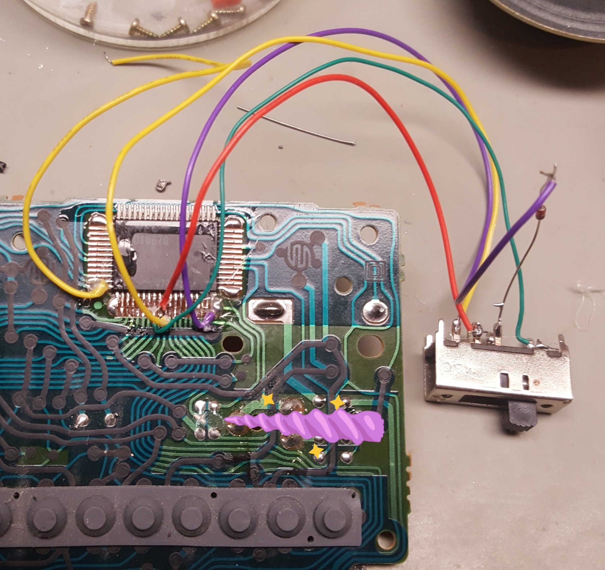
The tone / notes are mixed with the drums together and amplified, put through the speaker. Before that you can grab them from pin 12 (voice) and 13(drums). There might be an envelope channel on pin 11 - at least that;s what was said in one of the very well produced "keen on keys" videos.
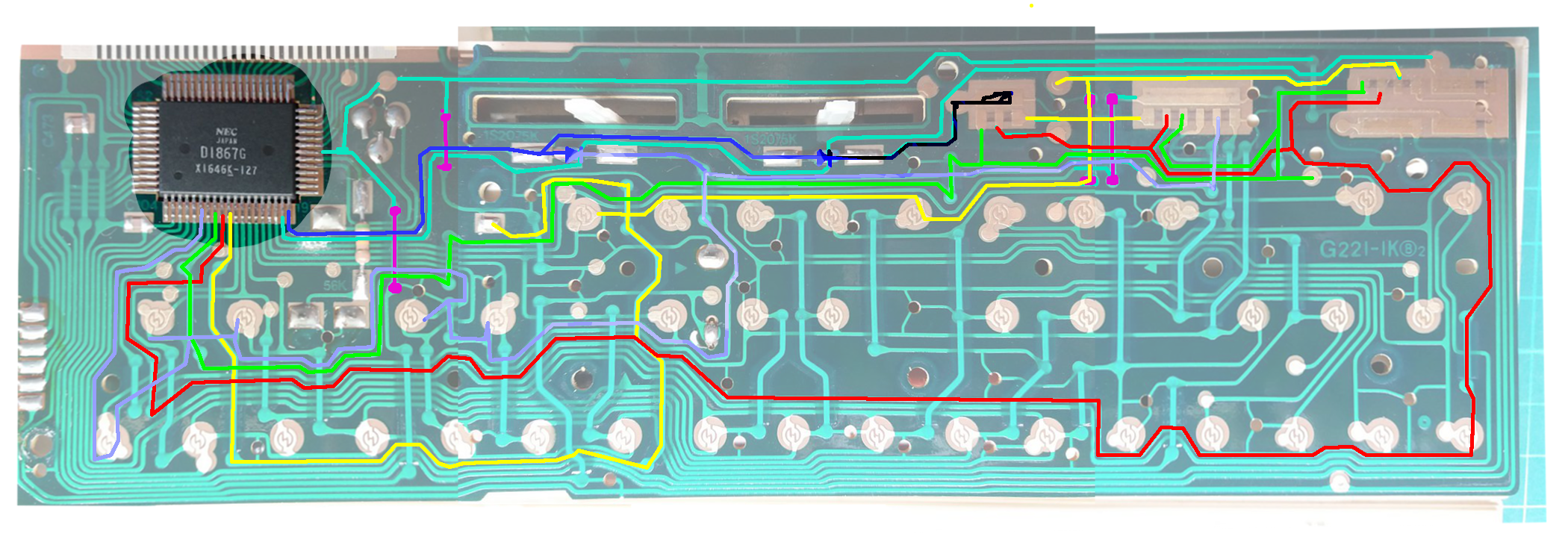
This is 3 pictures of the PCB of a VL-Tone VL-1 patched together to one. After a shoutout on twitter people were taking apart their VL-1s for me and took pictures, what a great thing! The main connections for the switch are on the bottom.
The PT-10 that I own has the same chip in the same case, so I wanted to see if I can add something to the keyboard, that wasn't there before. Wait, did I hack something?
Counting from the bottom left, pin 8, 9 and 10 are the octave switches, connected through a diode and a 3 way switch to the very last pin. You (sadly) have to cut where the unicorn is pointing to, but it's reversible if you really need to do that.
Next up should be tracing the ADSR switch, to get a new instrument out of it. At one point I need to see if I can connect an LED display to replace the LCD.
 davedarko
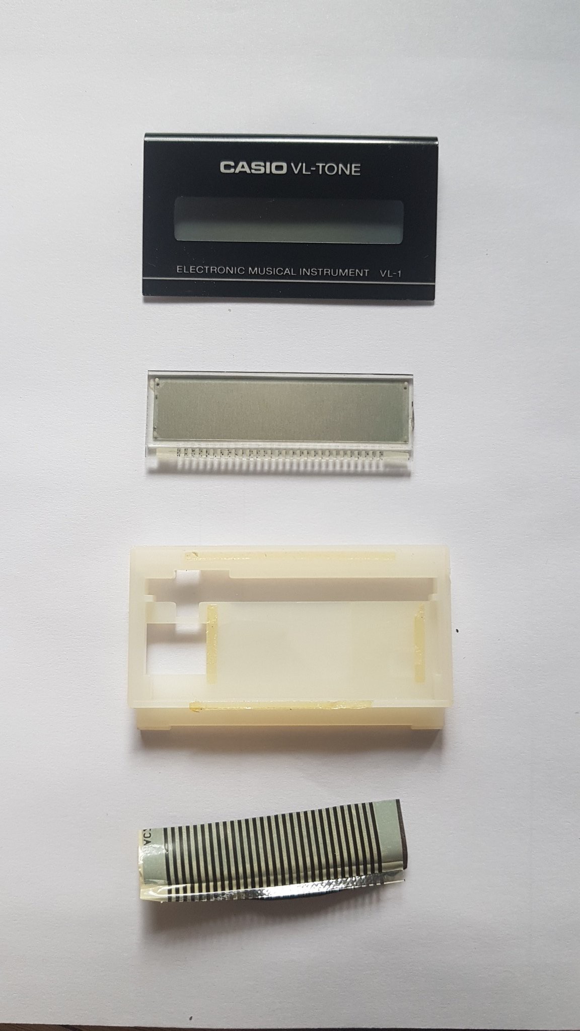
 The PT-10 that I own has the same chip in the same case, so I wanted to see if I can add something to the keyboard, that wasn't there before. Wait, did I hack something?