Bud Bennett
-
A 3D-printed Case
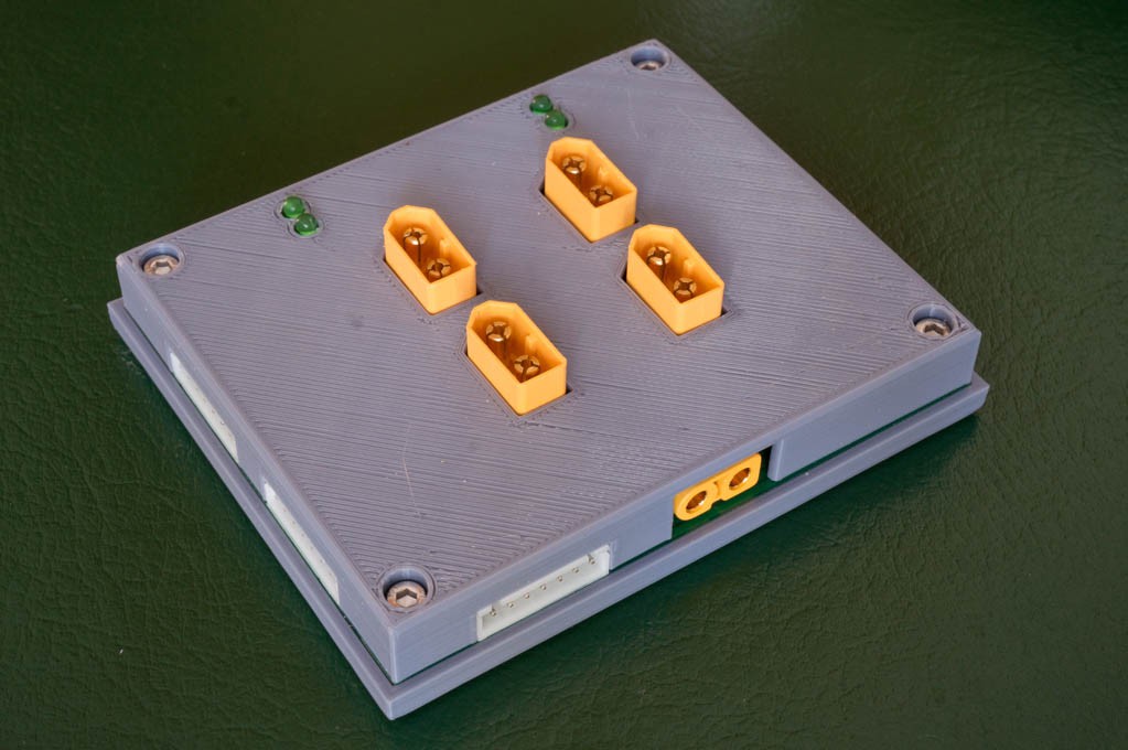
01/31/2022 at 15:51 • 0 commentsI bought a 3D printer in the summer of 2021, but was not able to print my own designs until I learned how to drive a 3D modeling application. I finally found FreeCAD, which makes more sense to me as an engineer. I was able to create this case after 4 tries:
![]()
The case requires 4 M3x12mm hex head bolts and M3 nuts. Additionally, I removed the SMD LEDs and soldered 3mm LEDs standing 8mm off the board. The through-hole LEDs are a bit brighter than the SMD LEDs. The .stl files are available in the files section of this project.
-
Rev.6 Testing
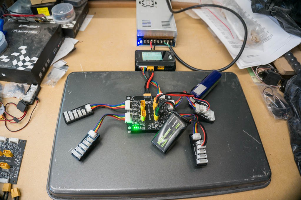
10/21/2021 at 02:24 • 0 comments![]()
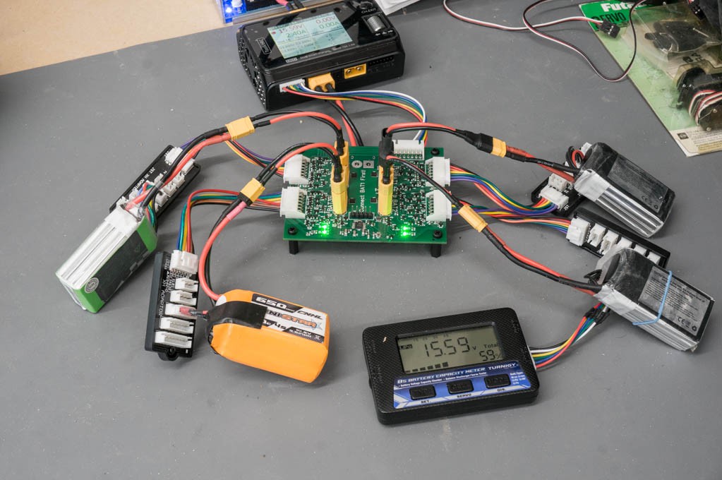
I received 5 populated boards from JLCPCB yesterday afternoon. I decided not to fully populate these boards since I had accumulated a few previous revision boards that had many of the components that I needed to make this one. Scavenging parts saved a bit of money.
I soldered the PIC into the board without programming it beforehand. After a bunch of errors, I finally succeeded in programing it in-situ...and it works!
This morning I began functional testing. It works well with both my SkyRC Q200 charger and my ToolkitRC M6D charger. It passed all of the simple tests, like adding batteries as they began to match voltage and draw current. The LED light when a battery comes online and turnoff when charging terminates.
It also passed a couple of tests for swapped battery survival. The tests involve three batteries: 2 with a low state of charge and another with a high state of charge. In the first test the lowest charge state battery connected with a swapped balance lead to another battery. The charger flagged a mismatch in the balance leads and refused to charge. The second test had the lowest voltage battery correctly plugged in with its balance leads and the other two batteries had swapped balance leads. When the charger began to charge the lowest battery was correctly connected to the balance leads, but the other two batteries had to wait until they were within 100mV before the balance leads were connected. It all worked the way it was supposed to.
I tested some parametrics:
Quiescent Current Draw (from BAT1): 130uA, 3S battery no balance leads connected.
Current Draw from BAT1 when BAT1 LED lit: 1.3mA, PIC is running @ 1MHz clock, 50uA draw from battery detection circuit, LED#1 is lit (425uA).
Current from BAT1 when charger input shorted: 13.3mA. This low current is because I used A BSS139 depletion mode MOSFET instead of a 100R resistor between the charger input and BAT1.
Ready for Prime Time:
I can't find anything really wrong with this design. I do have a short list of possible issues:
- It doesn't really work with 1S batteries. That is not a problem for me since I don't plan on using it for small 1S micro-drone batteries. The basic problem is that 1S batteries aren't equipped with any balance leads. If the balance leads are not plugged into the parallel charging station, the batteries will still charge but the LED indicators won't light up. So the user won't know which batteries are charging.
- If the user decides to not connect balance leads the LEDs won't light up. I don't believe this is a real problem for anybody, but time will tell.
-
Upgrading to a Micro-controller
09/25/2021 at 15:30 • 0 commentsEliminating Resistors in the Balance Lead Mux:
I was able to remove the resistors used in BAT1's balance leads by simply connecting BAT1's balance leads to the balance lead mux if BAT2-BAT4 were not charging. Unfortunately, high currents could flow temporarily in the mux switches if they didn't disconnect properly before connecting another battery. This is getting complicated enough to employ a micro-controller.
Fixing Problems Caused By Balancing Currents:
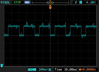
I found a very bad issue with the cell balancing operation of the ToolktRC M6D charger. The charger is yanking so hard on the balance lead mux that it exceeds the 100mV threshold of the swap detector comparators. Here's a scope trace of the problem:
![]()
The charger applies current to the mux to balance each cell. It does this periodically and then turns off the current in order to measure the voltage across the cell to decide whether to continue applying balance current. In the M6D's case it performs this cycle every 20ms. The PFET RDSon of the balance lead mux is about 50mR at Vgs = 3.6V, so two of them in series is ~100mR. Therefore the balancing current used by the M6D is about 2.5A. This is a single battery connected to the charger -- it will be lower as batteries are connected and the mux resistance is decreased. I also measured the battery voltage while the balance current was applied -- there was no measurable voltage movement at the battery.
This is a big problem because the swap comparator disconnects the balance leads from the charger every time the voltage across the mux exceeds ~100mV. Therefore the cells don't receive any balance adjustment.
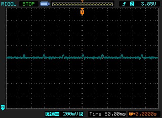
The SkyRC Q200 charger doesn't use such a large balance current. Here's what it looks like at the charger's balance leads:
![]()
The balancing current causes less than 50mV of voltage across the mux switches. It also happens at a much slower rate.
Going to the Dark Side:
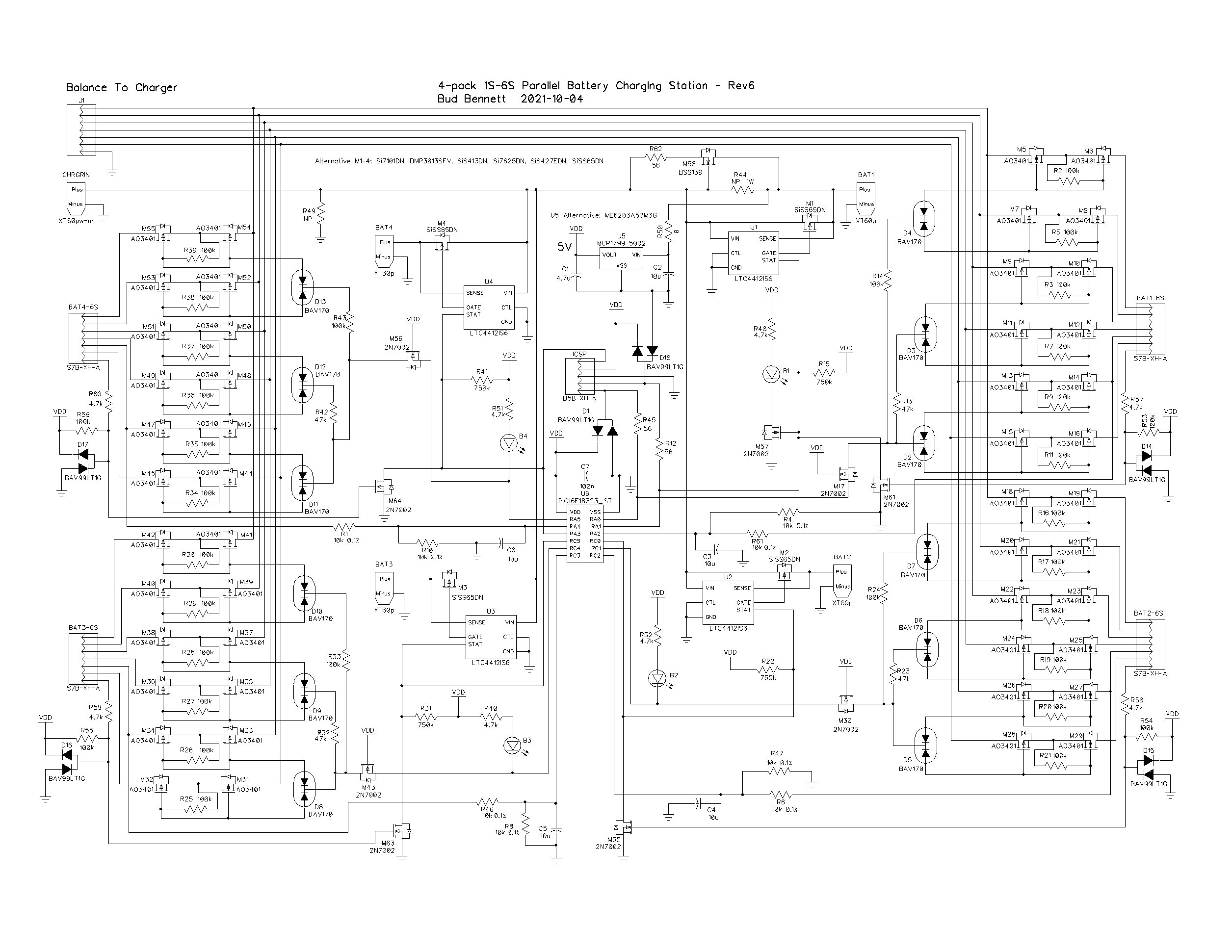
The only way that I could think of to solve this problem was to add a micro-controller -- a PIC 16F18323. This particular PIC is cheap at ~$1.00 in low quantities, comes in a 14-pin TSSOP package (which is relatively easy to hand solder), has a 10-bit ADC, and pretty low supply current even while running at a 1MHz system clock. And...I'm familiar with it. But several other PICs could be substituted into the circuit: 16F15223 or the 16F15323. The 16F15223 is the lowest cost of the bunch at $0.66, but its clock can't be set other than during a power on reset. (Even so, it still claims to draw less than 1mA @5V with a 1MHz clock.)
![]()
Adding the PIC removes the four swap comparators and a few other components to give some breathing room to the 500pin limit of the free Diptrace license. The PIC will use its internal 10-bit ADC to measure the battery voltages directly to determine if it is safe to connect the balance lead mux. It also will provide a break-before-make operation to the mux to make sure that no high currents flow between the batteries.
The 10-bit ADC has a resolution error of +/- 2.44mV. The resistor pair that divides the 2S voltage down to within the ADC's range have tolerances of 0.1%, which yields an error of +/- 3mV when the 2S voltage is 8.4V. That's about +/- 5mV around a 50mV detection threshold, or a 10% tolerance window. Of course, this is all subject to change, which is the beauty of using a PIC.
All of the PIC pins are used. The MCLR (master clear) input on pin 4 is disabled so it can be used as an input. Unfortunately when MCLR is configured this way the 5V programming option is not available, and MCLR has to be allowed to be taken to 9-10V (TBD) when programmed. This requires some judicious pin assignments for an In-Circuit-Serial-Programming (ICSP) interface to make it easier to make changes directly to the PIC without having to desolder it for re-programming. I've had ESD issues when programming PICs in the past so some diode protection was added to the clock and data inputs.
Flow Chart:
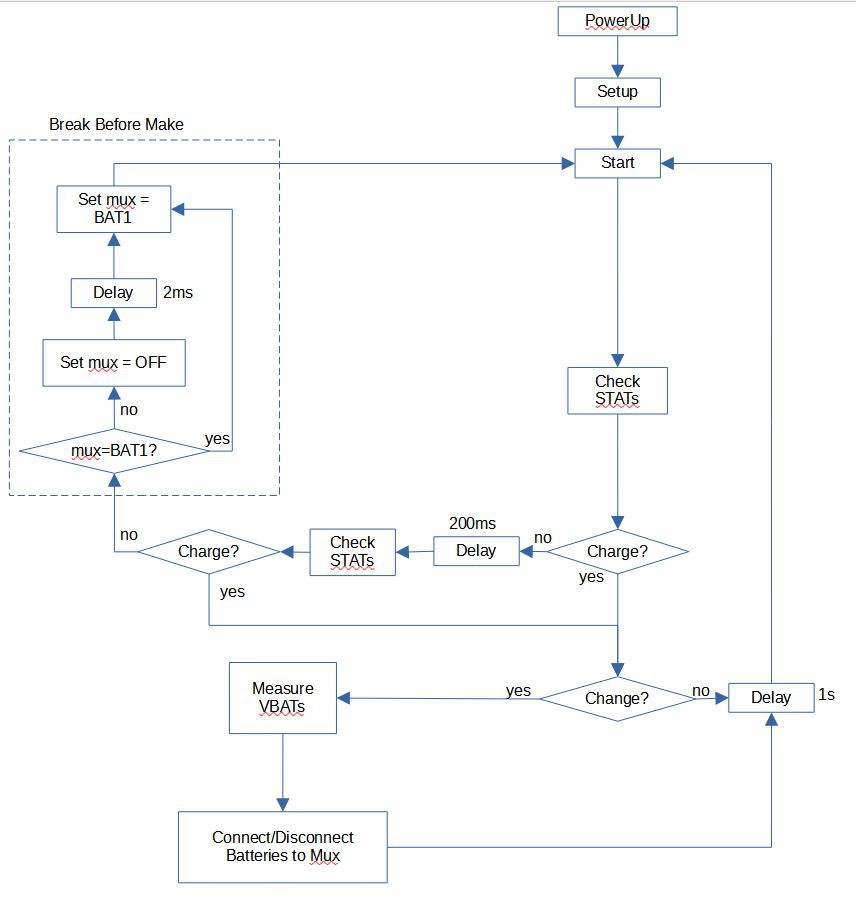
Here's my flow chart for programming the PIC:
![]()
When the PIC first powers up it checks the four STAT pins of the LTC4412 ICs to see if any of them are charging. If none are charging then it connects BAT1's balance leads to the charger by performing a break-before-make action with the mux switches. If the system was charging and then stops, a second STAT check is performed after a short delay to make sure that the charger has really stopped charging instead of taking a quick break to make some measurements before continuing. It would be very bad if the parallel board disconnected balance leads before the charger terminated. I've seen the B# LEDs flash during charger operation, but haven't been able to catch it on a scope to figure out what is happening. This is just insurance.
Note that BAT1 is configured slightly differently than the other three. The B1 LED is controlled by the STAT output of U1. This allows BAT1 to be connected to the mux without indicating it by lighting up the B1 LED. B2-B4 LEDs light up whenever they are connected to the mux.
When a charge condition is detected it drops into the lower loop to service it. If a change in the number of batteries being charged is detected, the ADC measures all of the 2S cell voltages of the batteries and decides whether to connect of disconnect the balance leads from the charger. If there is no change in charging condition it waits 1 second before returning to the starting point.
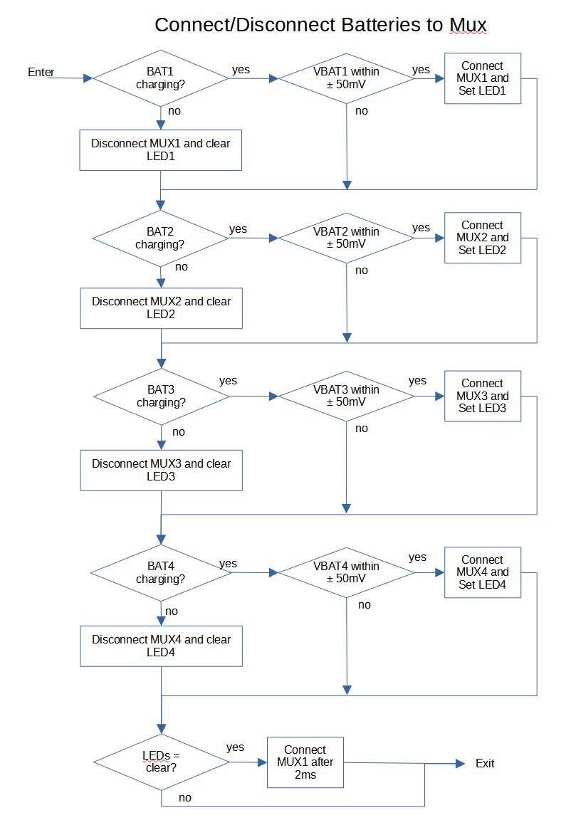
The flow of decision process to connect/disconnect batteries to the balance lead mux is shown below:
![]()
This isn't exactly what the PIC is doing, but it's close enough. There is a step, not shown, where if a battery is the first one to connect to the mux it must perform a break-before-make with the switches. In other cases, there is no need to worry about high currents flowing because the battery won't be connected if the voltage differences are too large. If all of the batteries are not charging then BAT1 is connected to the mux with break-before-make action.
-
Automated Assembly
09/17/2021 at 15:31 • 0 commentsThere are a lot of components on this board. It takes me 3-4 hours to pick and place all of the components properly and solder the board with a hot air station. Even then, there is a period of time required to insure that there are no open or missing connections, which are difficult to see.
JLCPCB Assembly:
JLCPCB offers an automated assembly service that will save a lot of time if you need to make multiple boards. The only catch is that you must use only components that JLCPCB offers, or components that are available through its sister company LCSC.
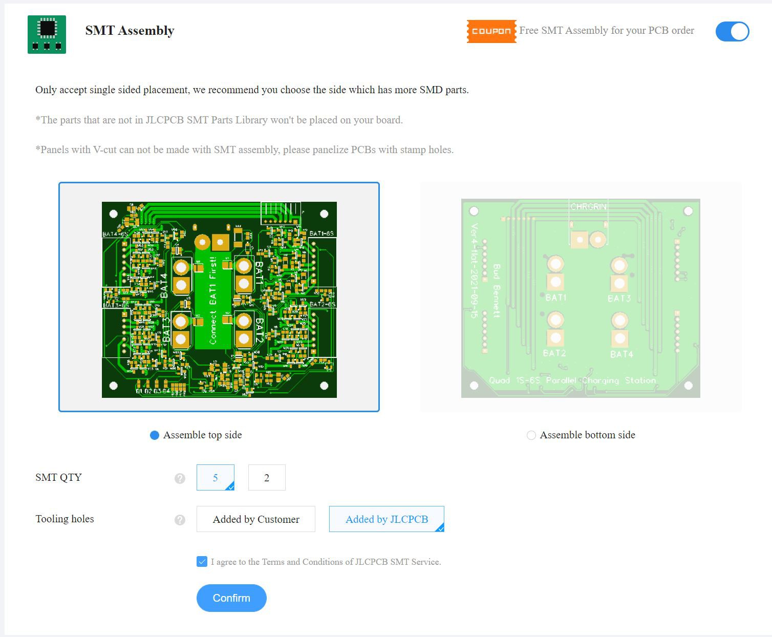
You can engage the service by clicking on the SMT Assembly button after you have uploaded the Gerber files to the website. This will require you to decide a few options:
![]()
In my case, I chose to have 5 boards assembled. They will only do single sided assembly which is not a problem since all of the SMD components are on the top. After you confirm your decision, you click on the NEXT button to go to the next page where you have to upload two files: your BOM and the CPL. These files are available in the files section of this project.
You are then presented with a comprehensive list of components to verify. JLCPCB has two kinds of components: 1. Basic components they already have loaded on the pick&place machines and there is no labor fee to use them, 2. Extended components require a $3 labor fee per component. I needed 8 Extended components for this design. In one case it was much cheaper to use the Extended JST3401 in place of the Basic AO3401. The design requires 144 pcs of this transistor and the price differential more than made up for the $3 fee. I also decided to use a Y5V rated capacitor instead of an X5R because I could not find a Basic 2.2uF capacitor rated for 50V/X5R and did not want to pay $3 for it.
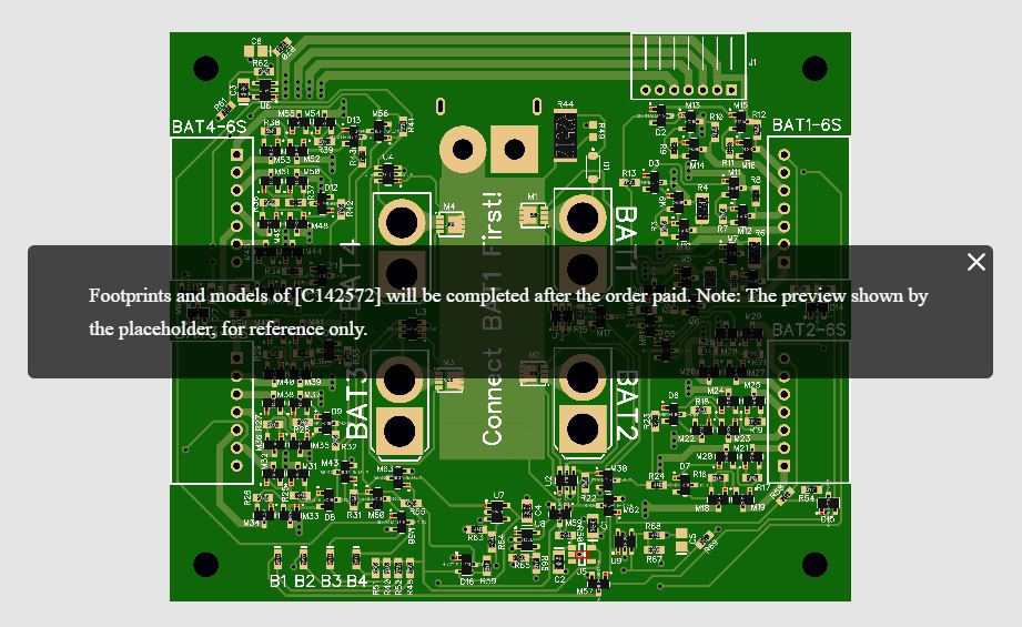
If they are low on stock, they will not place that component -- you will need to solder it yourself. At the time I write this they would not place the AON7405 PFET or the TPS79050 regulator. You can change components on the fly by selecting the problem component and providing a substitute from their catalog. I substituted a Si7101DN for the AON7405 and got this message:
![]()
Apparently, they don't have the footprint for the part already constructed and won't provide one until they get the money for the order. Fair enough. In my case, I just deleted the PFET and hand assembled them because I had some already on hand. I also deleted D1 from the build because I was not sure their pick&place would properly solder the substitution of a 1206 resistor for a SOD23 diode.
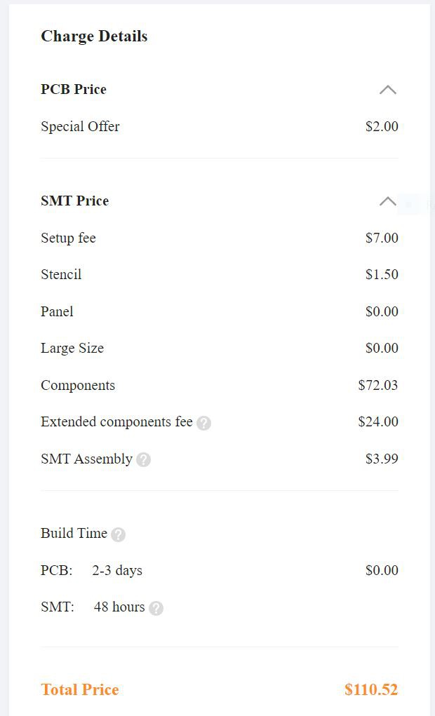
After you verify the component list the next page includes an image of all of the parts placed on the PCB. My Diptrace program had a lot of parts that had incorrect rotation. I fixed all of that before submitting the order -- the project's CPL file has the corrected rotation. At this time a quote for the cost is also provided:
![]()
The above quote includes the Si7101DN PFETs. JLCPCB offers a coupon to take $8 off the order. So you get 5 assembled boards for around $20/each + shipping. You still must add the TPS79050 and all of the through-hole components to the total.
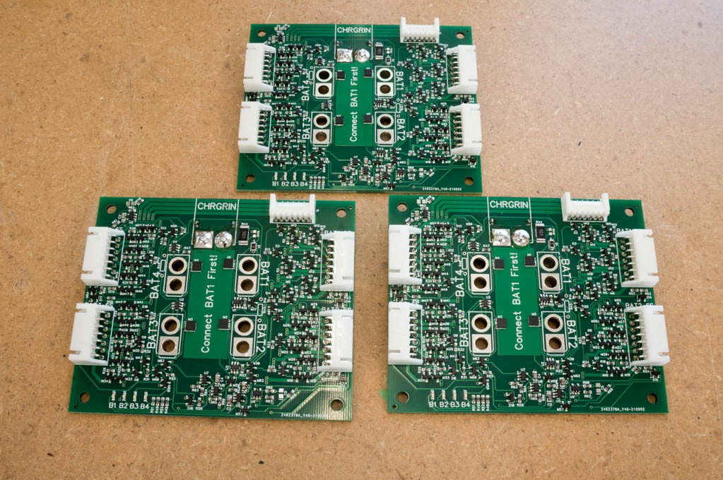
Here are three of the 5 boards that I received after I soldered the missing components:
![]()
I'm still missing the four XT60pb connectors. I'm really impressed by the results! No misplaced components or bad solder joints. Highly recommended.
-
Mea Culpa
09/15/2021 at 23:42 • 0 comments[Edit 2021-09-18: Changed resistor types to all 1206. Hopefully, this will help future proof the circuit to work with a larger assortment of chargers.]
I screwed up.
I calculated values for R1, R4, R6, R8, R10 and R12 based upon cell voltage differences instead of voltage tap differences. I also forgot to consider how a dead battery cell would affect power dissipations in these resistors. And just for good measure I did not bother to investigate how large these values could get before the ToolKitRC M6D charger would fail its checking algorithm.
Worst Case Survival:
The resistors that I referenced above are used to provide a relatively low resistance between the charger input and the balance leads of BAT1. When the charger checks for voltage and/or resistance to the balance leads it should be satisfied with the measurement it makes. (More on that later.) But the resistors should be able to survive worst case voltage difference between batteries and faulted batteries.
I consider a worst case condition is when a fully charged Li-Ion battery is plugged into BAT1 and a fully depleted battery with a dead cell ( a dead cell has zero volts across it) inserted into any other slot. A fully depleted Li-Ion has about 2.5V/cell, where a fully charged Li-Ion is 4.2V/cell. So the maximum voltage between each tap of the balance leads is given by:
Vmax = N*4.2V - (N-1)*2.5V, where N = Cell count at tap.
This voltage difference should not damage the resistor. By that I mean that it should not exceed its power rating. Typical power ratings of standard SMD resistors sizes are as follows:
0603 = 0.1W, 0805 = 0.125W, 1206 = 0.25W, 1210 = 0.5W, 2512 = 1W.
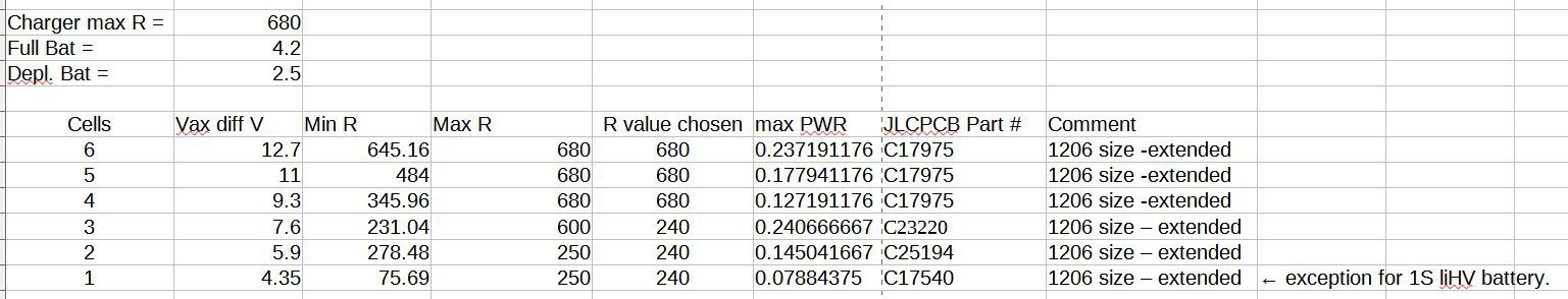
I chose to use 1206 size for all six resistors. So to get the minimum resistor value just divide the square of Vmax by its power rating. I did a spreadsheet to get the resistor values:
![]()
The ToolKit M6D maximum balance lead resistance test:
I was lazy when I selected 75R resistors to satisfy the charger. I knew that 1k was too large so I just tested 100R and it worked. Good enough, eh? Well, it was a bad assumption. I went back and inserted a potentiometer for R12, R10, R8 and R4 and varied it to find out what value the M6D considered a failure -- it was around 750R for R4 (10X higher than I was using), 590R for R8, and 240R for both R10 and R12. When you put this piece of information along with the above power dissipation limits then values and sizes in the above spreadsheet.
R1 = 680R, 1206 size
R6 = 680R, 1206 size
R4 = 680R, 1206 size
R8 = 240R, 1206 size
R10 = 240R, 1206 size
R12 = 240R, 1206 size
These large size resistors incur a $3 SMT Assembly setup fee for each value. I am using only two values to keep the setup fees to a minimum.
The Vmax = 4.35 for a single single cell is for LiHV chemistry. LiHV is not used for higher cell counts because it doesn't generate maximum voltages worse than Li-Ion.
Revision 4 Here We Come:
The size changes will force a PCB revision. I will also use this revision to flip the XT60PB connector from the bottom of the board to the top, to make it easier to design an enclosure for this board. I'm not sure that I will build Rev4, but I will update the files when the PCB changes are complete.
-
Changes for New Charger
05/25/2021 at 16:48 • 0 commentsI just purchased a ToolkitRC M6D charger, and a 600W 24V power supply to go with it. With this setup I can charge four 4S Lipos at 10.8A (2.7A/battery) in each slot and use channel 2 for another four batteries. This new charger doesn't behave like my older SkyRC chargers. Changes had to be made to the parallel charger circuitry to get it to work with the new charger.
![]()
When I received the new charger it refused to charge anything. The calibration was so far off that it could not reconcile the voltage at the main plug with what it was measuring on the balance leads. I kept getting a balance voltage error. This was the case whether I was using the parallel charger board or directly plugging the battery into the charger. I thought that it might be a software problem, so I installed new firmware -- no dice.
Time to download the manual and read it...ugh. I found out that if you hold down the enter key while powering up the charger that it will enter a calibration mode. When I did this it was obvious that the charger calibration was way off. I think the main battery voltage measurement was in error by nearly 2V. It is amazing how many different voltages and parameters can be adjusted...but were not adjusted by the factory. After calibrating all of the voltages against my trusty DVM, the unit came alive and decided it was OK to charge a battery!
But it was not OK to charge using the parallel charger. The diode, D1, was causing the charger to exit with an error. I shorted D1's leads but still could not get the charger to pass its sanity check phase. The next step was to reduce the resistors R1, R4, R6, R8, R10 and R12 from 1k to 75R. After that the charger was happy and started the charge cycle. I did a quick back-of-the-napkin analysis and concluded that the 75R resistors would not cause any real problems, such as heat dissipation or significant battery discharge.
The only negative to making the above changes is that it is possible for an LED to light up as a battery is connected. This is a nuisance, but not a real problem since the user will probably start the charging cycle soon after installing the batteries. After the charge cycle has ended there are no LEDs that remain lit.
I charged a few batteries in parallel with mixed results. The matching of the cell voltages at end of charge was not very good. I dug out my 10x loupe and examined the connections on the PCB very carefully, and found several open connections in the balance lead muxes. After fixing the soldering errors on the two boards I intended to use with this new charger things proceeded as expected. It now regularly charges all of the cells to within +/-10mV across all of the batteries.
At this point in time I can't foresee making any more changes to the parallel station. It is working well for me. This project will be marked "Completed" sometime soon.
-
Third Pass Testing
04/08/2021 at 19:10 • 0 commentsI finally got the Rev.3 PCBs and the extra components to populate them. I decided to transfer the more expensive components from the Rev.1 and Rev.2 boards to save some money. This took some extra time, but worth it.
There are a lot of components, so it took some time to populate the board. I wish that I had ordered a paste mask stencil along with the PCBs as it would have save a lot of time with the solder paste syringe. I usually don't buy a stencil because it usually gets tossed when I have to do a revision.
The first function that I tested was that the battery LEDs did not light when a battery was not populated in the charging station. That works as designed.
Next, I tested the overall charging function (which should not have changed) and verified that the batteries in all four slots were being properly charged and the balance leads connected.
Finally, I tested the situation where three (or more) batteries are connected to the charger, but two of the batteries have swapped balance leads:
- I connected a 2.2Ah 3S LiPo into BAT1 and the balance lead connector for BAT1. This battery had a voltage of 11.7V.
- I connected a 2.2Ah 3S LiPo into BAT3, with a voltage of 11.6V, but connected its balance leads into the BAT4 connector.
- I connected a 2.2Ah 3S LiPo into BAT4, with a voltage of 11.93V, but connected its balance leads into the BAT3 connector.
I applied 100mA of charging current -- BAT3 LED lit, as expected. As the voltage increased on BAT3 the BAT1 LED turned on dimly. I put the scope on the BAT1 LED and found that it was oscillating with low duty cycle at about 200Hz. As I increased the charger current from 100mA to about 400mA the frequency increased and the duty cycle changed until the LED was no longer oscillating. This behavior was expected.
I increased the charging current to 1A, which is a more normal situation, and noticed that the BAT4 LED came on at full brightness when BAT4 began to charge. I backed off on the charger current and the LED turned off. When the voltage on the two charging batteries increased further the BAT4 LED lit. I was not able to get the BAT4 LED to oscillate. It appears that the Rev.3 design is functioning as intended and saving the balance lead PFETs from overdissipating when balance leads are connected improperly. I put my calibrated finger on the PFETs while they were experiencing current drain from the misconnected batteries -- I could not feel much increase in temperature.
At this point I believe that the design is pretty solid. I will publish the Gerbers and a BOM to the files section.
-
Third Pass Design Issues
03/18/2021 at 18:16 • 0 commentsI was nearly set to accept the second pass design as the final product until I started thinking about other stuff that could go wrong. I revisited the issue of when the user accidentally misconnects the balance leads between two batteries. I was completely wrong in my previous thinking that the balance lead PFET switches would survive -- they won't without some help. The problem doesn't become clear until you analyze what happens when three, or more, batteries are connected to the station and two of the batteries have misconnected balance leads. (The details section of this project must be corrected.)
Even before the charger is enabled, there is a problem. The lowest voltage battery will draw current from BAT1 and connect its balance leads to the charger balance leads. If two batteries have misconnected balance leads then it is possible for the battery with the higher voltage to have its balance leads connected to the lower voltage battery -- very bad.
What happens then is that the higher voltage battery dumps current into the low voltage battery without regard to any current limit. Fortunately, the internal battery resistance comes into play and the two batteries connect and disconnect at a rapid frequency until the voltages equalize, or the PFETs overheat and fail.
Things get worse when the charger begins charging the connected batteries. The added charger current tends to inhibit the internal battery resistance from disconnecting the balance leads and the PFETs fail quickly.
I verified the above scenario with simulation and experiments on the bench with controlled battery voltages. It's not pretty.
*************************
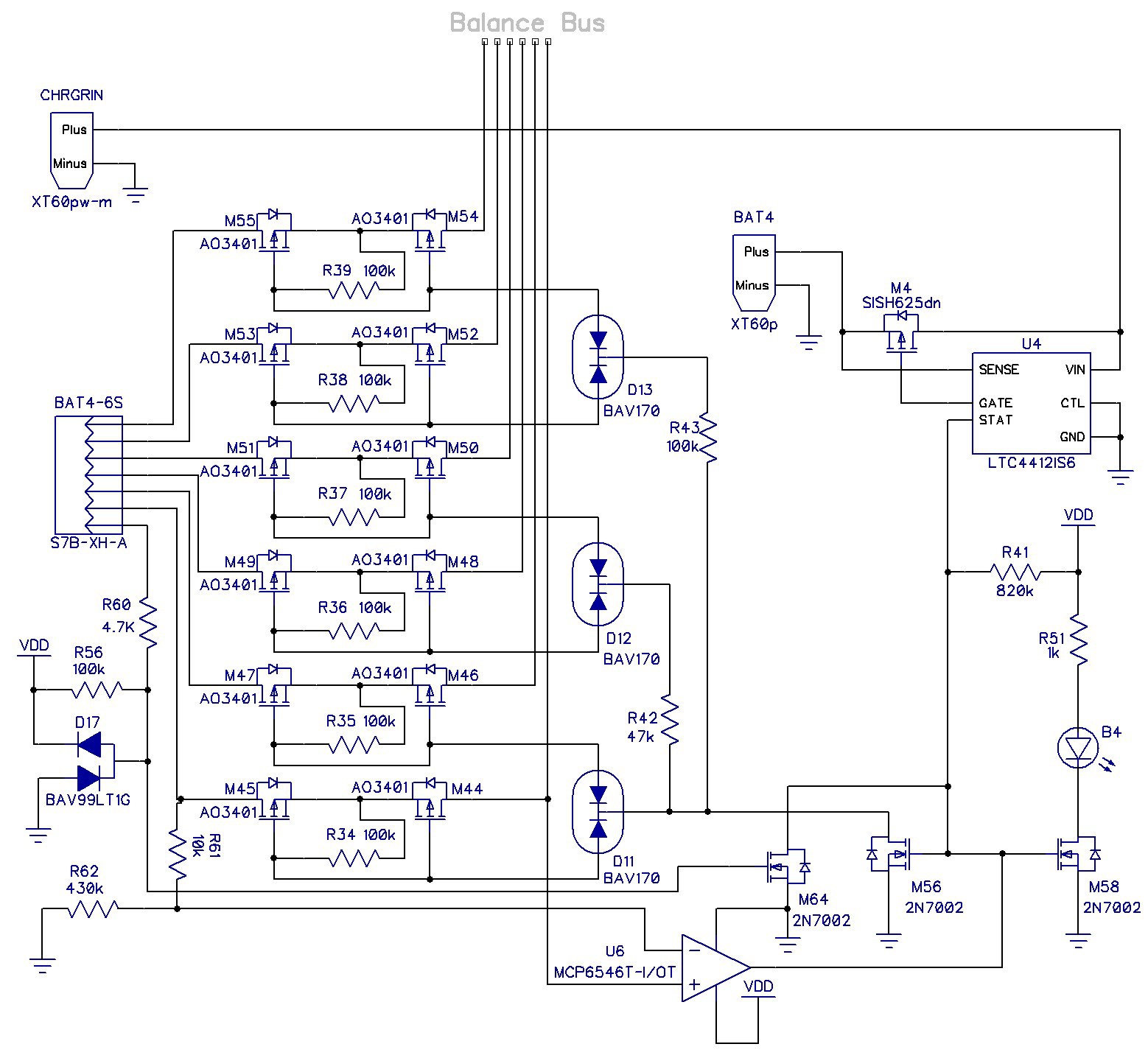
I think there is a solution. I added a comparator to sense if the first cell of a battery is above the voltage on the first cell balance lead that is connected to the charger and prevent the PFET switches from closing. This is a schematic of one of the channels with the comparator in place:
![]()
The MCP6546 is relatively cheap, open-drain, comes in a SOT23-5 package, and has built-in 3mV hysteresis. R61 and R62 create a voltage drop of between 70mV-100mV. If the batteries first cell voltage is higher than what is on the balance lead bus then the comparator pulls down on M56 and prevents the PFET switches from connecting. It's not foolproof. The battery voltages will eventually equalize and the PFETs will get connected, but there will be much less voltage and current to deal with so the PFETs should survive.
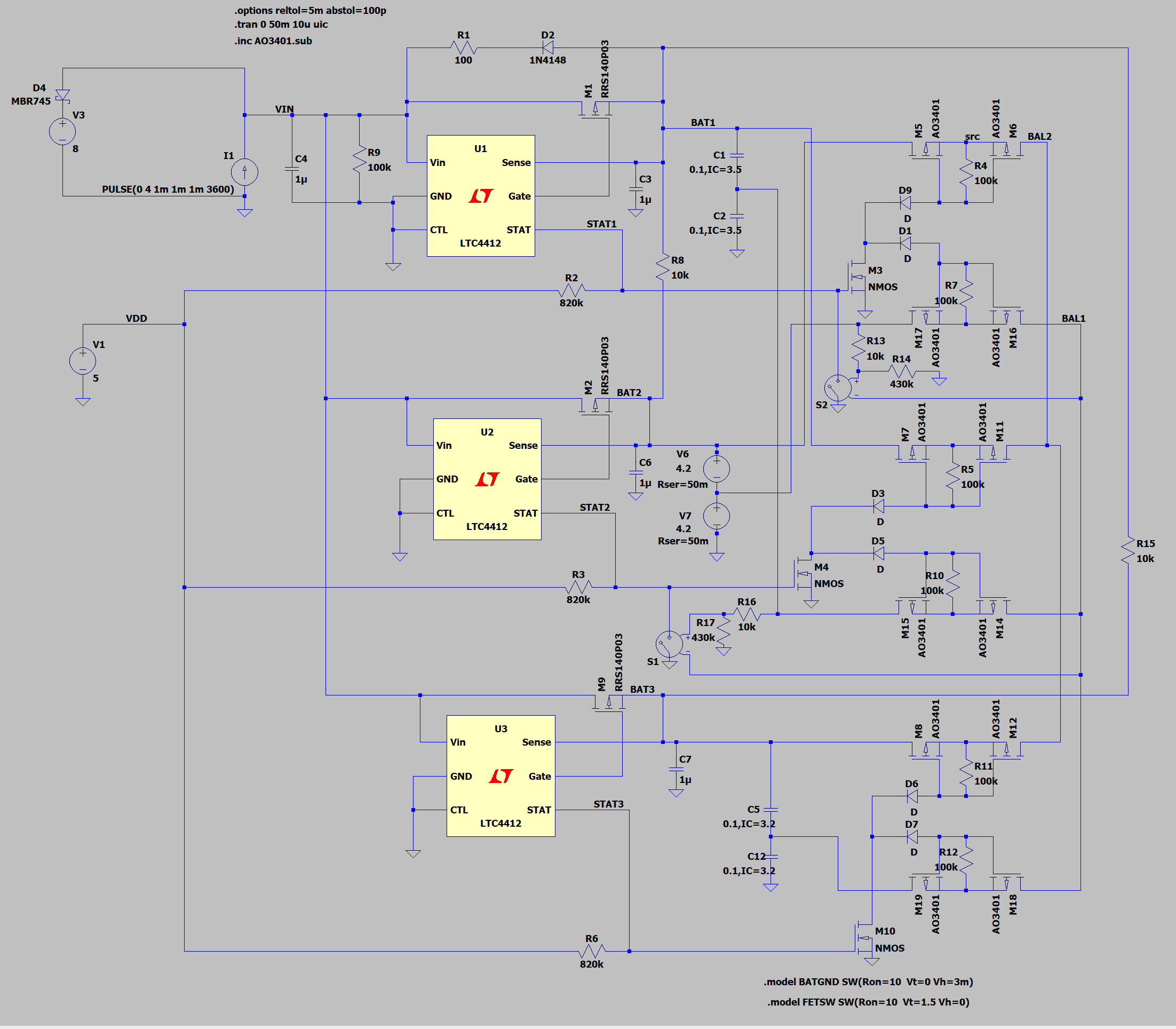
I seems to function correctly. I simulated it in LTspice with the schematic below:
![]()
A full blown implementation is too simulation intensive, so I simplified it a bit. The comparators are implemented with voltage controlled switches, S1 and S2.. I also had to use generic NMOS devices and diodes because the more complicated models were generating artifacts in the simulation. The charger is located in the upper-left -- just a current source and voltage clamp. I modeled the 2-cell batteries with large values of capacitance with 25m-50m Ohm series resistance tagged with an initial voltage condition.
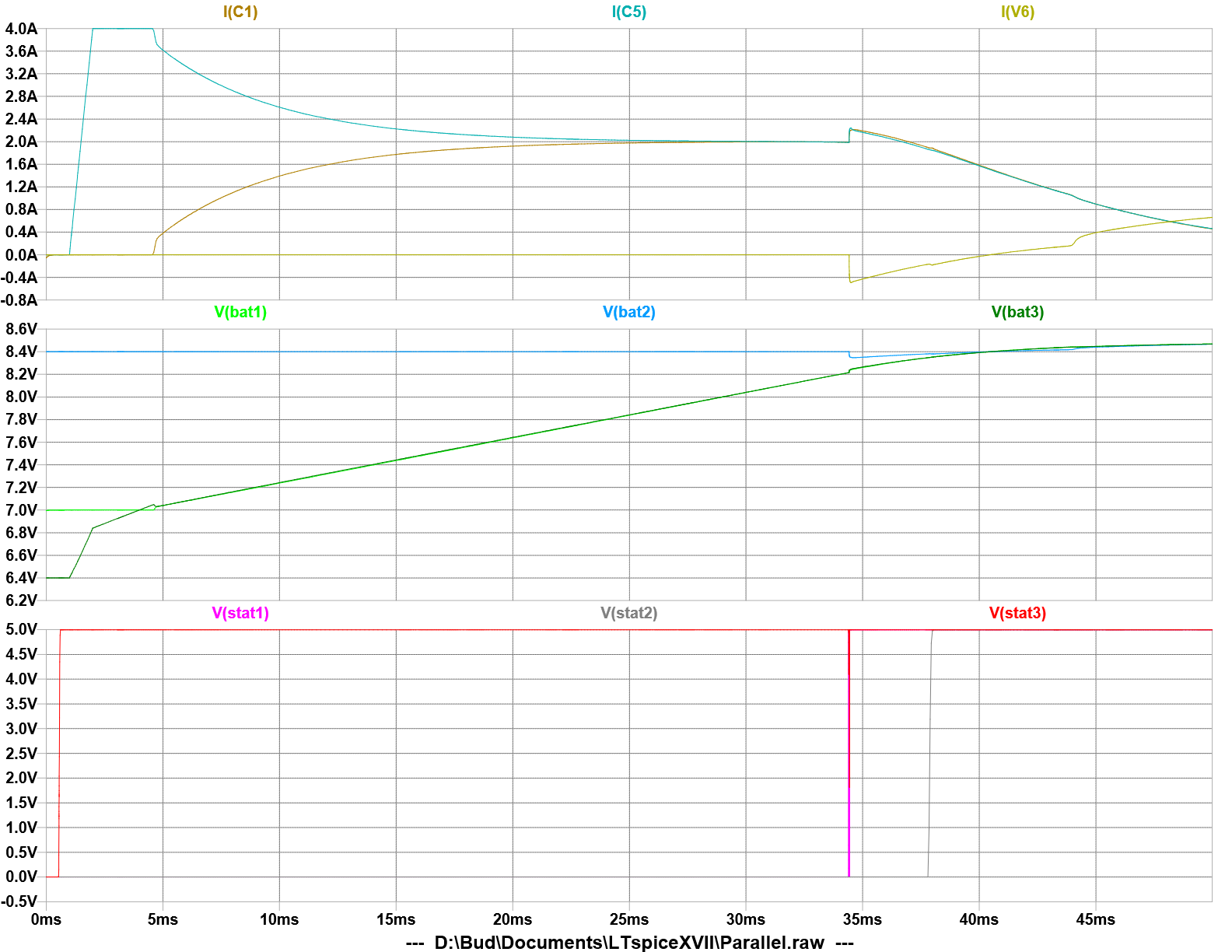
The result of the simulation is shown in the plots below:
![]()
The full charging cycle takes place in 50ms. When the charger is engaged at 4A, it begins to charge the battery with the lowest voltage, BAT3, at full current. When BAT3 rises to 3.5V/cell the current begins to share with BAT1, but BAT1's STAT pin is held low by the comparator. This is normal charging operation because the STAT pin doesn't affect the behavior of the LTC4412. Note that BAT1's balance leads are not connected to the balance lead bus. Neither are BAT2's balance leads connected due to the mis-wiring.
When the voltage of the two batteries gets within 200mV of BAT2 (at about 34ms) the comparator allows the balance leads to connect and STAT1 is asserted. This causes current to flow from BAT2 into the other two batteries through the balance leads. Note also that the charger is not charging BAT2 at this point since its voltage is not equal to or below the other two batteries. The current through the PFET switches is less than 0.5A, which they can survive as a continuous condition with only 12.5mW of power dissipation. The balance leads of BAT1 are still not connected because the LTC4412 for BAT2 has not asserted its STAT pin.
The charger continues to charge the batteries until the voltage equalizes on all three batteries (at about 38ms). Then the STAT2 signal goes high and now all the balance leads are connected. The charging cycle will complete normally now.
Other Pass 3 changes:
I decided to add some circuitry to inhibit the charge LED indicators from lighting up if there was no battery present. There is a pullup resistor, R56, connected to the GND pin of the balance lead connector. The voltage at that pin feeds the gate of a 2N7002 NMOS transistor, M64, with it's drain connected to the STAT pin of the LTC4412. If there is no battery present M64 keeps the balance leads disconnected and the LED turned off. This is also helpful if the balance leads are attached before the battery lead since no current can flow inadvertently through the balance leads until the battery is connected to GND.
R60 and D17 provide ESD protection for M64.
-
Second Pass
03/10/2021 at 03:21 • 0 commentsNot much to report about with these new PCBs, but I did learn something.
I added a LED to report the charging status of each battery. Unfortunately, I did not account for how dominant the BAT1 connection is. Here is the problem:
- If BAT1 is not the highest voltage of all the connected batteries, then when the charger begins to charge the unpopulated battery LEDs light up. I expected this.
- If Bat1 is the highest voltage of all connected batteries, then when the charger begins to charge, the unpopulated battery LEDs are not lit. I did not expect this, but it is not really a problem since the user knows which batteries are populated and can discount any activity from the LEDs of unpopulated batteries.
It is still better to know which batteries are charging and which are not.
The addition of resistors into the GND connection of the balance leads did not cure the problem of the charger claiming that the battery was reverse polarity when the last battery was removed from the parallel charging station.
-
Results From First Prototypes
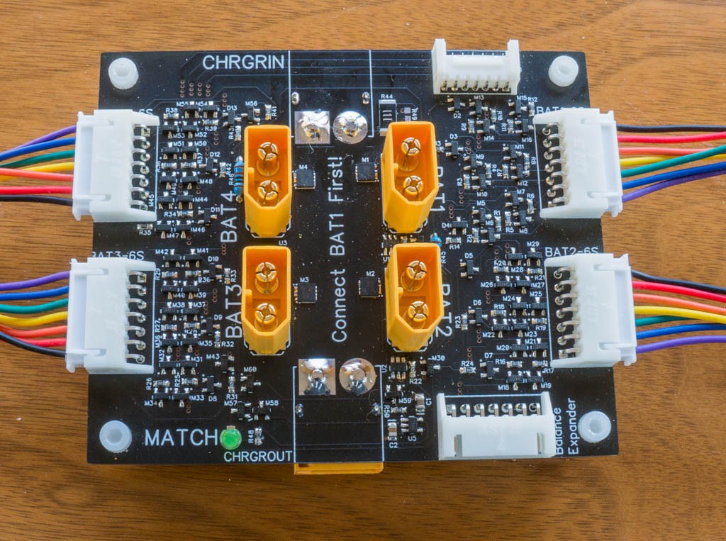
02/09/2021 at 18:07 • 0 comments![]()
This project was delayed by other priorities for more than 3 weeks. I decided that the most prudent way to proceed was to just populate the BAT1 channel and the 5V regulator to see if the charger complained about anything when I tried to charge a battery. Before connecting a battery, I measured some voltages at the gates of the balance lead FETs, the charger input, and the voltage drop across M1 (the ideal diode PFET). All the voltages appeared to be correct, and the drop across M1 was only 25mV with a 2.5A load current (that's 10mOhm.) I also applied >25V at the battery and balance leads to make sure they were capable of 6S LiPo voltages.
The charger (a SkyRC Q200) did not complain and proceeded to charge the battery (a 1.6Ah/3S LiPo) without issue.
Then I populated all of the PCB and began testing the parallel charging function. I was not very rigorous about this testing. Basically, I just attached BAT1 and BAT2 and started the charger. When the green light lit I checked the cell voltages to see if there were any outliers. I did the same thing when adding BAT3 and BAT4. After all of the batteries were in place and the MATCH LED was lit, I stopped the charger and reset the charger current to 4X the battery Ah, which in this case was 6.4A. This channel of the charger was limited to 50W, so I could only get 4.2A from the charger at 12V output.
I swapped out the 3S batteries for 4 850mAh 4S LiPos. I charged these batteries from about 3.8V/cell to completion -- it took 35 minutes. I immediately checked all of the batteries using the battery meter function of the charger:
BAT1 - 16.78V (4.19, 4.20, 4.18, 4.20)
BAT2 - 16.77V (4.19, 4.20, 4.18, 4.20)
BAT3 - 16.76V (4.19, 4.19, 4.18, 4.20)
BAT4 - 16.77V (4.19, 4.19, 4.18, 4.20)
The batteries are within +/- 10mV, which is a pretty good result (though I'm not sure that the charger or parallel station had anything to do with that result.)
The only "glitch" that I noticed was that the charger would complain about a reverse battery insertion when I unplugged the last battery from the parallel station. That may be a result of the balance leads not grounded on the parallel station board -- I did not want any ground loops.
I also tested it with an old SkyRC B6 charger (50W single battery charger) and it worked just fine.
Conclusions:
As far as I can tell, after some pretty basic testing, it works as intended. After playing with it for a couple of days I have a list of small changes:
- Add LEDs on each battery channel to indicate how many batteries are matching so the user can increase the charging current to speed up the process, if desired.
- Add resistors to the balance lead grounds to possibly prevent the complaint from the charger about reverse voltage.
- Both right-angle XT-60 connectors had to be placed on the bottom of the board because I got the connectivity wrong. If there is a revision, this should be corrected.
- Make some right-angle XT60 to XT30 adapters to allow for some more room when charging LiPos with short leads intended for quad copters.
No-Worries Parallel Battery Charging Station
A safe (and better) alternative to parallel battery charging .