Close
0%
0%

Amrel Power Supply UX Mod

Add a rotary encoder to an Amrel programmable power supply to improve the user interface.

Similar projects worth following
87 views
0 followers
A pair of HP E3640s were the go-to power supplies on my bench for years, but I unloaded them to shrink my pile of test equipment. I still had an Amrel LPS-301 with a bad LCD that did the job well... but I found its six-button keypad interface cumbersome compared to the HP's simple rotary controls.

While taking apart the Amrel's front panel to replace the LCD I thought it would be fun to modify the control interface too... so I added a push-button rotary encoder and a microcontroller to emulate the keypad which - for my taste anyway - greatly improved the usability.

The Amrel LPS-301 supply is a programmable 30V/2A unit that has a front-panel keypad and an isolated serial interface for computer control.  The six-keys on the keypad set voltage/current values and enable/disable the output... and I don't love it.  It really needs a knob!  The LCD on my unit was bad so while I had it all apart to replace the display I figured I'd try to improve the controls.

Here's a shot of the cumbersome-to-use front panel:

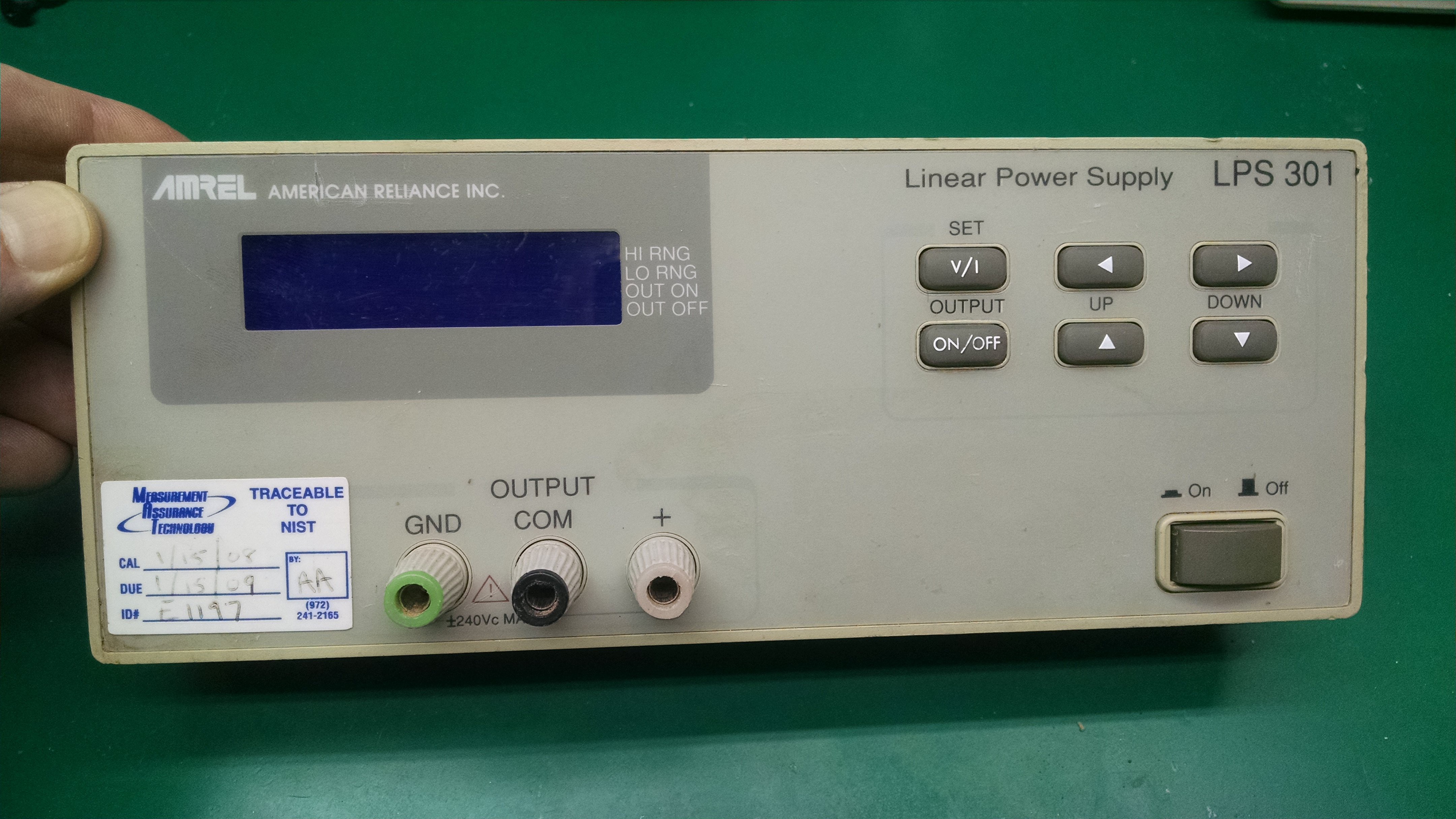
Incidentally, it looks like this front panel - and the mainboard inside it - is used for the other power supplies in the same product family.  There's a dual channel supply, and a supply with a fixed 5-volt output that share many parts.


CURRENT BEHAVIOR:

Entering a voltage value with the Amrel keypad requires pressing the "v/i" key to select voltage, then the "up/down" keys to set the 0-9 value for the first of five digits, then the "right" key to select the next digit, the "up/down" keys to set that digit, the "right" key again to select the next - agh!... and repeating this for each remaining digit.  The power supply changes to the new voltage and exits the v/i mode after setting the last digit and hitting the "right" key a final time.  At this point the "left/right" and "up/down" keys can change any digit of the set voltage.

Once you start setting a voltage or current you have go through all five digits to get out of that mode.  It would be nice if I could just set the first digit or two and activate it without pressing the "right" key four more times.


PROPOSED BEHAVIOR:

I'd like to add a single encoder with a pushbutton to perform the same voltage/current set operations that the keypad handles.  I also want to be able to enable/disable the output with the encoder button and I want the option to exit voltage/current set mode without setting every single digit.  I whipped up a rough diagram to show how it would work:

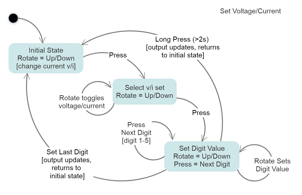
Rotating the encoder simply alters any voltage (or current) that is currently active.  A button press enters the voltage/current "set mode" where subsequent rotation toggles between "voltage" or "current".  Another button press moves to the first digit - just like using the keypad "right" key - and rotating selects the value.  Yet another button press moves to the next digit, rotation selects that value... repeat for all remaining digits.  After setting all digits the final button press changes the power supply to the new voltage.  If you start setting a voltage and do a long press - or do nothing for 3 seconds - whatever value you've got so far is kept and the voltage/current set mode exits (a "right" key is sent for any remaining digits).


HARDWARE IMPLEMENTATION:

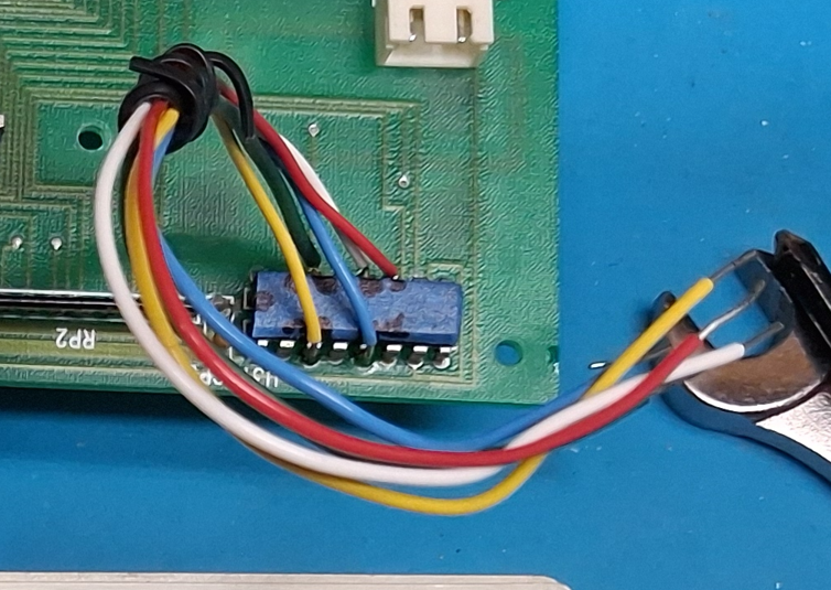
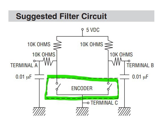
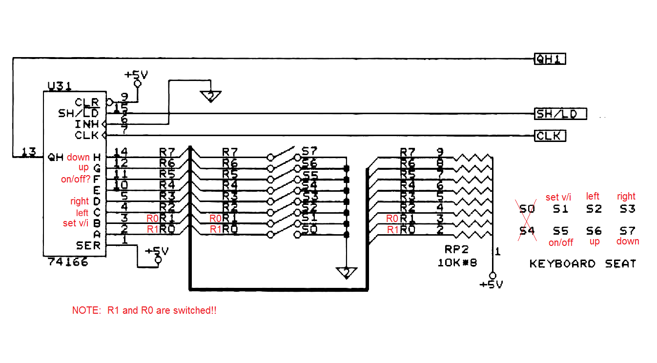
I initially thought I'd use the encoder and microcontroller to send commands over the existing serial interface to set voltage/current but I figured there may be some lag, and I didn't want to tie up the interface.  I then considered talking directly to the onboard 80c31 controller so I started checking out the schematics from the service manual.  I noticed that each key has it's own active-low signal line and is connected to a 74166 shift register with an external pull-up... I realized that by using a buffer chip with hi-z/open-collector outputs I could manipulate the keypad signals directly, without having to interface with the 80c31 or modify the board at all

I had some 3-state buffers, an HW-040 encoder breakout board, and various micros lying around - but decided to eliminate the buffer chip and emulate an open-collector output in software, using an Arduino.  I connected up the encoder, whipped up sketch, soldered a few wires onto the appropriate 74166 pins and... nothing.  The Arduino was generating pulses based on my encoder inputs, but they were much too short and the power supply couldn't detect them.  I increased the pulses to 50ms and it worked!...

Read more »

20260513_083623.mp4

Short demo of selecting a voltage and letting the Arduino automatically press the right button to set it. Also shows turning the output on/off

MPEG-4 Video - 43.18 MB - 06/11/2026 at 04:58

Download

amrel_ps_encoder.ino

ino - 17.58 kB - 06/11/2026 at 04:03

Download

  • 1
    Tap into to the keypad buttons

    You'll need to connect wires from the Arduino input pins to the keypad button signals.  The keypad button signals are most easily tapped at the 74166 shift register that's on the front panel board.  The schematic in the details section shows which connections are for which keypad signals - and they are in the code comments above - but I've also included them here:

    KEY_ONOFF signal goes to Arduino Digital pin 12 - comes off 74166 F/pin 11

    KEY_VI signal goes to Arduino Digital pin 6 - comes off 74166 B/pin 3

    KEY_RIGHT signal goes to Arduino Digital pin 7 - comes off 74166 D/pin 5

    KEY_LEFT signal goes to Arduino Digital pin 11 - comes off 74166 C/pin 4

    KEY_UP signal goes to Arduino Digital pin 8 - comes off 74166 G/pin 12

    KEY_DOWN signal goes to Arduino Digital pin 9 - comes off 74166 H/pin 14

    Here are 5 of the keypad signals tapped from the 74166.  KEY_LEFT is not yet connected, but will go to pin 4, between the yellow and blue wires: 

  • 2
    Connect the rotary encoder

    The rotary encoder is a Bourns pec11, and I mounted it on a small bit of pc board using the filter circuit suggested in the datasheet.  The datasheet can be found here:  https://www.bourns.com/docs/Product-Datasheets/PEC11R.pdf, and here's the circuit:

    Bourns didn't do a great job with the circuit diagram... the encoder itself is what I highlighted in green, and all the other components are external and need to be added.  Terminals A and B on the encoder are the two switches inside the green highlighted rectangle, and terminal C connects to GND.  The pushbutton signal is not shown in this diagram.

    The circuit has 5 signal lines that need to be connected to the Arduino - Vcc (5v), GND, Button and the A and B signal lines for the encoder position.  The connections to the Arduino are as follows (there are also comments in the Arduino code):

    Vcc and GND are connected to the corresponding Vcc/GND pins on the Arduino

    The PEC-11 button signal connect to Arduino Digital pin 3 (this is Interrupt INT1)

    The PEC-11 A signal goes to Arduino Digital pin 4

    The PEC-11 B signal goes to Arduino Digital pin 5

    If you get this together and find that the encoder direction is going the wrong way, swap the A/B signal lines. 

  • 3
    Upload Arduino code to device

    I used a pro-mini that does not have an on-board USB controller, so I needed a separate board to program the device.  You may not need that depending on which board you choose to use.

    Here's the code:

    /*
     * Amrel Encoder (started as pro_mini_encoder)
     *  * Revision Info:
     * 1.00 rotate to change current setting. click to enter v/i selection mode and rotate to choose v/i,  *      then click to set digit 1, click again to set next digit
     * 1.10 adding extra input to detect keypad presses.  need to move PIN_BT_INT to another pin
     *
     * Add an encoder to the Amrel LPS-30x power supply to control setting voltage/current
     *  * Present Operation:
     *  There are 6 buttons on the Amrel unit to set the value of output current and voltage and to
     *  enable/disable the output
     *  V/I Set Mode
     *   - 'V/I' is pressed to enter voltage/current set mode and subsequent presses toggle between  *     'set voltage' and 'set current'
     *   - The right '>' key moves focus to the first digit, and the value (0-9) is set using the
     *     'up' and 'down' keys
     *   - Once the focused digit is set, pressing '>' goes to the next digit (five total)
     *   - Once the last digit is set, pressing '>' will set the supply to the current value
     *   - If V/I mode is entered by mistake, the only way to get out of it is pressing the right
     *     button to get through each digit
     *  Output ON
     *   - The up/down buttons are used to set the output value starting from the rightmost digit
     *   - The left/right buttons can be used to first select a digit, at which point the up/down buttons  *     will set the digit's value
     *   - Changes are immediate
     *  Output OFF
     *   - The left/right buttons do nothing
     *   - The up/down buttons are used to set the output value starting from the rightmost digit
     *   - Changes are immediate
     *  * Encoder Operation:
     *  V/I Set Mode
     *   - A short-press on the encoder button sends a 'V/I' keypress to enter V/I set mode
     *     A long-press will exit V/I set mode and set the supply to the current value (it sends however  *     many 'right' keypresses are needed to exit)
     *   - If in v/i set mode, rotating the encoder (cw or ccw) sends a 'V/I' keypress to selects voltage  *     or current (will continually send 'V/I' keypress if the encoder is continually rotated)
     *   - When the desired mode is shown, pressing the button sends a 'right' keypress to switch from 'V/I'  *     select mode to digit set mode
     *   - Rotating the encoder now selects 0-9 for the current digit (cw sends 'up', ccw sends 'down' keypress)
     *   - Pressing the button sends a 'right' keypress to save the digit value and move to the next digit
     *   - After the last (fifth) digit is set, the final button press sends a final 'right' keypress and
     *     sets the supply to the current value
     *   - Once V/I mode is entered, it can be exited by pressing the encoder button to get through each digit,  *     OR by long-pressing the encoder button, OR by doing nothing for 4 seconds
     *  Normal Operation (not in V/I set mode, and output is ON or OFF)
     *   - Rotating the encoder sets the output value starting from the rightmost digit (cw sends 'up', ccw  *     sends 'down' keypress)
     *   - Changes are immediate
     *  * Considerations:
     *   - send only one pulse at a time (and let each pulse finish, with some padding)
     *   - the encoder does not currently send 'left' keypresses
     *    * Debug Defines:
     *   - DEBUG will enable debug statement output on serial port
     *   - DEBUG_PULSE will output a square wave with same duration as key pulses on DEBUG_PIN
     *  * Rotary encoder routines thanks to Brainy-Bits "Best code to use with a KY-040 Rotary Encoder? Let's find out!"
     * Timer code thanks to Adafruit "https://learn.adafruit.com/multi-tasking-the-arduino-part-2/timers"
     *
     * For faster speed, use direct port access techniques ("http://www.arduino.cc/en/Reference/PortManipulation"), per
     * Adafruit encoder example at: "https://learn.adafruit.com/pro-trinket-rotary-encoder/example-rotary-encoder-volume-control"  *
     * Modified checkEncoder to read the clock and data once rather than for every if... is this ok??
     */
    
    // debug defines
    //#define DEBUG_PULSE
    #define DEBUG
    #ifdef DEBUG
      #define Debug_println(s) Serial.println(s)
      #define Debug_print(s) Serial.print(s)
    #else
      #define Debug_println(s)
      #define Debug_print(s)
    #endif
    
    // encoder pins
    #define PIN_KP_INT 2   // Interrupt INT0 used to detect keypad button presses (the keypad buttons we want to scan will be and'ed together)
    #define PIN_BT_INT 3   // Interrupt INT1 used to detect a press of the encoder button
    #define PIN_DT 4
    #define PIN_CLK 5      // change from 2 to 5 (move 5/KEY_ONOFF to 12 and use 2 for PIN_KEYPAD interrupt input)
    #define ARDUINO_PIND PIND
    
    // digital output pins
    #define INPUT_MODE INPUT_PULLUP // INPUT_PULLUP or INPUT (use INPUT_PULLUP when not using Amrel's pullups)
    #define KEY_ONOFF 12  // red (74166 F, pin 11) moved from 5 to 12
    #define KEY_VI 6      // yellow (74166 B, pin 3)
    #define KEY_RIGHT 7   // blue (74166 D, pin 5)
    #define KEY_LEFT 11   // black (74166 C, pin 4)
    #define KEY_UP 8      // black/white (74166 G, pin 12)
    #define KEY_DOWN 9    // green (74166 H, pin 14)
    #define DEBUG_PIN 10
    
    // operating modes
    #define MODE_NORMAL 0
    #define MODE_VISET 1
    
    #define DEBOUNCE_DELAY 10
    #define KEYPRESS_LENGTH 60
    #define KEYPRESS_PADDING 20
    #define LONG_PRESS_LENGTH 600
    
    #ifdef DEBUG
      char strUp[3] = "UP";
      char strDown[5] = "DOWN";
      char strRight[6] = "RIGHT";
      char strLeft[5] = "LEFT";
      char strVI[4] = "V/I";
      char strONOFF[6] = "ONOFF";
    #endif
    
    // state variables
    static int displayCounter = 4;
    byte mode = 0;
    volatile bool keypadPressed = false;
    volatile bool buttonDown = false;
    volatile bool timingButtonPress;
    volatile int buttonTimer = 0;
    volatile int timeoutTimer = 0;
    
    // new checkEncoder
    static uint8_t enc_prev_pos   = 0;
    static uint8_t enc_flags      = 0;
    static char    sw_was_pressed = 0;
    
    byte keyPressed = 0;
    byte nextKeyPressed = 0;
    volatile byte keyPressTime = 0;
    bool keyPressActive = false;
    byte viSetDigitIndex = 0;
    bool viSetLongPressExit = false;
    
    #ifdef DEBUG_PULSE
    bool debugPulseVal = false;
    volatile byte debugPulseTime = 0;
    #endif
    
    void setup() {
      // init state vars
      mode = MODE_NORMAL;
      keypadPressed = false;
      buttonDown = false;
      buttonTimer = 0;
      timingButtonPress = false;
      timeoutTimer = 0;
    
      // get an initial reading on the encoder pins
      if (digitalRead(PIN_CLK) == LOW) {
        enc_prev_pos |= (1 << 0);
      }
      if (digitalRead(PIN_DT) == LOW) {
        enc_prev_pos |= (1 << 1);
      }
    
      keyPressed = 0;
      nextKeyPressed = 0;
      keyPressActive = false;
      keyPressTime = 0;
      viSetDigitIndex = 0;
      viSetLongPressExit = false;
    
      // setup pins
      pinMode(PIN_KP_INT, INPUT_PULLUP);
      pinMode(PIN_BT_INT, INPUT_PULLUP);
      pinMode(PIN_CLK, INPUT_PULLUP);
      pinMode(PIN_DT, INPUT_PULLUP);
      pinMode(KEY_VI, INPUT_MODE); // use INPUT if you have external pullups
      pinMode(KEY_RIGHT, INPUT_MODE);
      pinMode(KEY_LEFT, INPUT_MODE);
      pinMode(KEY_UP, INPUT_MODE);
      pinMode(KEY_DOWN, INPUT_MODE);
      pinMode(KEY_ONOFF, INPUT_MODE);
    
    #ifdef DEBUG_PULSE
      pinMode(DEBUG_PIN, INPUT_MODE);
    #endif
    
      #ifdef DEBUG
        Serial.begin (115200);
      #endif
      Debug_println("Amrel Encoder");
    
      // Timer0 is already used for millis() - we'll just interrupt somewhere
      // in the middle and call the "_int1_ButtonDOWN" function
      OCR0A = 0x7F;
      TIMSK0 |= _BV(OCIE0A);
    
      // EIFR = bit (INTF0);  // clear flag for interrupt 0
      EIFR = bit (INTF1);  // clear flag for interrupt 1
      // attachInterrupt(digitalPinToInterrupt(PIN_KP_INT), _int0_KeypadPressed, FALLING);  // keypad presses on interrupt 0 = pin 2
      attachInterrupt(digitalPinToInterrupt(PIN_BT_INT), _int1_ButtonDOWN, FALLING);  // encoder pin on interrupt 1 = pin 3
    }
    
    // Interrupt is called once a millisecond, to update the pulse timing(s)
    SIGNAL(TIMER0_COMPA_vect) {
      if (keyPressActive)
        keyPressTime ++;
      if (timingButtonPress)
        buttonTimer ++;
      timeoutTimer ++;
    #ifdef DEBUG_PULSE
      debugPulseTime ++;
    #endif
    }
    
    void _int0_KeypadPressed() {
      detachInterrupt(digitalPinToInterrupt(PIN_KP_INT));
      keypadPressed = true;
    }
    
    void _int1_ButtonDOWN() {
      detachInterrupt(digitalPinToInterrupt(PIN_BT_INT));
      buttonDown = true;
    }
    
    void loop() {
      // encoder rotation sends different key presses depending on mode
      checkEncoder();
    
      // to detect a short or long encoder press... if the button is pressed for > long duration it's a long
      // press, otherwise it's a short press.  when a FALLING ext interrupt occurs, detach the interrupt, set   // buttonDown and start counting milleseconds while the button is still low.  re-attach the interrupt   // after the short or long press is processed.  
      // **sometimes, a short was occuring immediately after a long press.  not sure if this was caused by   // bouncing on the button up or an interrupt that was queued - but ignore any short press with a   // duration less than 10 milliseconds or so   if (buttonDown) {
        buttonDown = false;
        timingButtonPress = true;
        Debug_print("down ");
        timeoutTimer = 0;
      } else if (keypadPressed) {
        keypadPressed = false;
        // do the keypad press stuff here
        Debug_print("keypad pressed ");
        // clear interrupt flag and re-attach
        // EIFR = bit (INTF0);  // clear flag for interrupt 0
        // attachInterrupt(digitalPinToInterrupt(PIN_KP_INT), _int0_KeypadPressed, FALLING);  // keypad presses on interrupt 0 = pin 2
      } else if (timingButtonPress) {
        if (digitalRead(PIN_BT_INT) == 1 || buttonTimer > LONG_PRESS_LENGTH) {
          // button is no longer pressed, determine if it was long or short
          Debug_print("up ");
          Debug_print(buttonTimer);
                if (buttonTimer > LONG_PRESS_LENGTH) {
            Debug_println(" LONG");
            doEncoderLongPress();
          } else if (buttonTimer > DEBOUNCE_DELAY) { // ignore short press if it's immediately after a long
            Debug_println(" SHORT");
            doEncoderShortPress();
          } else {         Debug_println(" IGNORE");
          }
    
          buttonDown = false;
          timingButtonPress = false;
          buttonTimer = 0;
    
          // clear interrupt flag and re-attach
          EIFR = bit (INTF1);  // clear flag for interrupt 1
          attachInterrupt(digitalPinToInterrupt(PIN_BT_INT), _int1_ButtonDOWN, FALLING);  // encoder pin on interrupt 1 = pin 3
        }
      } else if (timeoutTimer > (LONG_PRESS_LENGTH * 7) && mode == MODE_VISET) {
        Debug_println(" TIMEOUT");
        // on a timeout, exit the viSet mode (can do this by calling doEncoderLongPress as long as
        // the current mode == MODE_VISET)
        doEncoderLongPress();
      }
      // manage key presses...   // - if keyPressActive, keep pulse low for KEYPRESS_LENGTH, but don't allow another keypress
      //   to start until KEYPRESS_LENGTH + KEYPRESS_PADDING (or supply won't detect the press)
      // - if !keyPressActive, handle long press exit from viSet and check for any key to send
      if (keyPressActive) {
        // if there's an active keypress, kill output when pulse time elapses
        // (but don't start another keypress when one is already active)
        if (keyPressed > 0 && (keyPressTime > KEYPRESS_LENGTH)){
          // stop keypress pulse but keep it active until pad time elapses
          pinMode(keyPressed, INPUT_MODE);
          //Debug_println("end pulse");
          keyPressed = 0;
        } else if (keyPressTime > (KEYPRESS_LENGTH + KEYPRESS_PADDING)) {
          // set keypress inactive when keypress_length + padding has elapsed
          //Debug_println("keyPress done");
          keyPressActive = false;
          keyPressTime = 0;
        }
      } else {
        // process the next key press.  first, check to see if we're supposed to be exiting viSet     // mode from a long press... if so, let doShortKeyPress set up the next key press
        if (viSetLongPressExit) {
          doEncoderShortPress();
        }
        // process next key press
        if (nextKeyPressed > 0) {
          // pull the associated key pin low for x duration
          //Debug_println("start pulse");
          keyPressed = nextKeyPressed;
          nextKeyPressed = 0;
          Debug_print("sending keyress ");
          Debug_println(getKeyName(keyPressed));
          keyPressActive = true;
          keyPressTime = 0;
          digitalWrite(keyPressed, LOW);
          pinMode(keyPressed, OUTPUT);
          // let main loop delay for KEYPRESS_LENGTH ms
        }
      }
      // debug output square wave on DEBUG_PIN
    #ifdef DEBUG_PULSE
      if (debugPulseTime > KEYPRESS_LENGTH + KEYPRESS_PADDING){
        if (debugPulseVal){
          digitalWrite(DEBUG_PIN, LOW);
          pinMode(DEBUG_PIN, OUTPUT);
        } else {
          pinMode(DEBUG_PIN, INPUT_MODE);
        }
        debugPulseVal = !debugPulseVal;
        debugPulseTime = 0;
      }
    #endif
    }
    
    void queueKeyPress(byte key) {
      // there is no queue... this just sets the next key to be processed by the main loop
      Debug_print("queue keypress ");
      Debug_println(getKeyName(key));
      nextKeyPressed = key;
    }
    
    #ifdef DEBUG
    char * getKeyName(byte key) {
      if (key == 5) {
        return strONOFF;
      } else if (key == 6) {
        return strVI;
      } else if (key == 7) {
        return strRight;  
      } else if (key == 8) {
        return strUp;  
      } else if (key == 9) {
        return strDown;  
      }
    }
    #endif
    
    void doEncoderShortPress() {
      timeoutTimer = 0;
      displayCounter = 0;
      Debug_println(displayCounter);
    
      // a short press in mode_normal switches to mode_viset, and a short press in mode_viset   // selects v or i, then continues setting digits and finally goes back to mode_normal
      if (mode == MODE_VISET) {
        viSetDigitIndex ++;
        if (viSetDigitIndex == 1) {       Debug_println("Set Digit 1");
        }
        if (viSetDigitIndex > 1) {       // v or i set was selected, need to enter/continue digit set mode - send 'right' key
          Debug_print("Set Digit");
          Debug_println(viSetDigitIndex);
          queueKeyPress(KEY_RIGHT);
        }
        if (viSetDigitIndex >= 6) {
          // this occurs when the last digit is set - clear mode, digit index and longPressExit
          Debug_println("NORM");
          viSetDigitIndex = 0;
          viSetLongPressExit = false;
          mode = MODE_NORMAL;
        }
      } else { // (mode == MODE_NORMAL)
        // if we're in mode_normal, go to mode_viset
        // once in viSet mode, any encoder rotation toggles v/i
        viSetDigitIndex = 0;
        mode = MODE_VISET;
        // send 'v/i' keypress
        queueKeyPress(KEY_VI);
      }
    }
    
    void doEncoderLongPress() {
      timeoutTimer = 0;
      if (mode == MODE_VISET) {
        // a long press in v/i set mode kicks off the process to exit the operation.  the main     // loop takes care of sending however many 'right' keys are required
        if (viSetDigitIndex < 6) {       Debug_println("viSet exit");
          viSetLongPressExit = true;
        }
      } else { // (mode == MODE_NORMAL)
        // a long press in normal mode sends ONOFF to enable the power supply output
        // send 'on/off' keypress
        queueKeyPress(KEY_ONOFF);
      }
    }
    
    void doEncoderRight() {
      timeoutTimer = 0;
      if (mode == MODE_VISET && viSetDigitIndex == 0) { // selecting v or i set - not setting a digit
        // send 'v/i' key press to toggle v/i
        queueKeyPress(KEY_VI);
      } else {  // setting a digit - increment value
        // send 'up' key press
        queueKeyPress(KEY_UP);
      }
    }
    
    void doEncoderLeft() {
      timeoutTimer = 0;
      if (mode == MODE_VISET && viSetDigitIndex == 0) { // selecting v or i set - not setting a digit
        // send 'v/i' key press to toggle v/i
        queueKeyPress(KEY_VI);
      } else {  // setting a digit - decrement value     // send 'down' key press
        queueKeyPress(KEY_DOWN);
      }
    }
    
    void checkEncoder() {
      int8_t enc_action = 0; // 1 or -1 if moved, sign is direction
    
      // note: for better performance, the code will use
      // direct port access techniques
      // http://www.arduino.cc/en/Reference/PortManipulation
      uint8_t enc_cur_pos = 0;
      // read in the encoder state first
      if (bit_is_clear(ARDUINO_PIND, PIN_CLK)) {
        enc_cur_pos |= (1 << 0);
      }
      if (bit_is_clear(ARDUINO_PIND, PIN_DT)) {
        enc_cur_pos |= (1 << 1);
      }
    
      // if any rotation at all
      if (enc_cur_pos != enc_prev_pos) {
        if (enc_prev_pos == 0x00) {
          // this is the first edge
          if (enc_cur_pos == 0x01) {
            enc_flags |= (1 << 0);
          } else if (enc_cur_pos == 0x02) {
            enc_flags |= (1 << 1);
          }
        }
    
        if (enc_cur_pos == 0x03) {
          // this is when the encoder is in the middle of a "step"
          enc_flags |= (1 << 4);
        } else if (enc_cur_pos == 0x00) {
          // this is the final edge
          if (enc_prev_pos == 0x02) {
            enc_flags |= (1 << 2);
          } else if (enc_prev_pos == 0x01) {
            enc_flags |= (1 << 3);
          }
    
          // check the first and last edge
          // or maybe one edge is missing, if missing then require the middle state
          // this will reject bounces and false movements
          if (bit_is_set(enc_flags, 0) && (bit_is_set(enc_flags, 2) || bit_is_set(enc_flags, 4))) {
            enc_action = 1;
          } else if (bit_is_set(enc_flags, 2) && (bit_is_set(enc_flags, 0) || bit_is_set(enc_flags, 4))) {
            enc_action = 1;
          } else if (bit_is_set(enc_flags, 1) && (bit_is_set(enc_flags, 3) || bit_is_set(enc_flags, 4))) {
            enc_action = -1;
          } else if (bit_is_set(enc_flags, 3) && (bit_is_set(enc_flags, 1) || bit_is_set(enc_flags, 4))) {
            enc_action = -1;
          }
          enc_flags = 0; // reset for next time
        }
      }
    
      enc_prev_pos = enc_cur_pos;
    
      // enc_action > 0 is cw/right, < 0 is ccw/left
      if (enc_action > 0) {
        // TrinketHidCombo.pressMultimediaKey(MMKEY_VOL_UP);  // Clockwise, send multimedia volume up
        displayCounter ++;
        doEncoderRight();
      } else if (enc_action < 0) {
        // TrinketHidCombo.pressMultimediaKey(MMKEY_VOL_DOWN); // Counterclockwise, is multimedia volume down
        displayCounter --;
        doEncoderLeft();
      }
    }
    

View all 3 instructions

Enjoy this project?

Share

Discussions

Does this project spark your interest?

Become a member to follow this project and never miss any updates