This is my attempt at a LiPo-based battery pack for Texas Instruments Calculators that use the BP01 battery pack, specifically the TI-58, TI-58C, and TI-59. I thought it would be fun to design a 3D printed housing and re-use the circuitry from my rechargeable HP LiPo battery pack. This is a follow-on project to my Classic HP Calculator LiPo battery pack.
LiPo chemistry has very specific care-and-feeding when it comes to recharging, the original TI AC adapter and built-in charging circuitry will not suffice. For this reason, I include a USB receptacle, which allows for charging when removed from the calculator.
The basic idea is to use a gold-flashed (ENIG) PCB as the contact substrate, and mount the LiPo, USB micro B receptacle, and charging circuitry on the opposite side. A charging LED is placed on the same side as the contact pads, but in areas where there will be no mechanical interference. A 3D printed plastic holder ties it all together, and mates with the TI calculator case.
The Housing
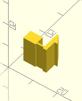
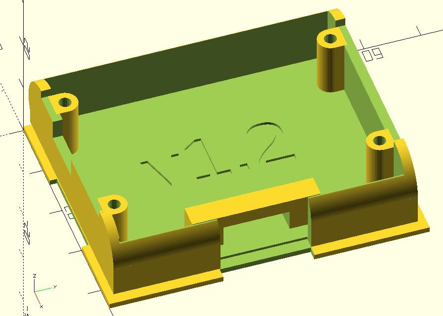
By far this was the most challenging part of this project. I have several original TI BP01 battery packs, so I was able to carefully measure them and create a 3D model using OpenSCAD. This is essentially a 3D solid 'programming language' which (for me) is much easier to work with than an interactive 3D CAD program. It took several iterations to arrive at a working holder design that would 3D print (FDM) reliably. Note that the holder is best printed "flat side down", but that this orientation is not ideal for the retention tab; it wants to break along the FDM layers. I have had good luck with PLA+ material, and even better results with PTEG. Care when inserting and removing is still recommended, however - these 3D holders are nowhere near as strong as their injection-molded predecessors!
The PCB
The PCB holds the USB micro B connector, the charging circuitry, the protection circuitry, a connector for the LiPo battery, and most importantly the pads that mate with the contacts in the calculator. The overall size of the PCB is 53mm x 28mm. The material is 1.6mm thick FR4. So that the contact pads do not tarnish over time, I chose a gold-flash treatment (ENIG).
The schematic and PCB were designed using KiCAD.
The LiPo Battery
I wanted a 1S (3.7V) LiPo battery in the neighborhood of 1200mAhr that would fit within the confines of the original pack envelope. This led me to a size "103040" LiPo battery.
Putting It All Together
Pretty self-explanatory. I used 0805 size components to allow for easy hand-soldering. Note that D1 (LED) and Z1 (Zener) are both polarized, so pay attention to that. Soldering the USB connector requires a fine-tip iron and some patience, or a hot-air solder station. I use the latter with very good results.
Connect the battery to the PCB, double-checking that the polarity of the LiPo is matching the "+" and "-" marks on the PCB. Place the battery into the holder in between the two pairs of screw bosses, and then press the PCB into place above it. Four #2 self-tapping stainless steel screws secure the PCB into the 3D printed holder.
Charge It
Connect a micro-B cable to the board and charge the LiPo battery. The LED will stay lit during the charging process, and extinguish when it is completed. The charge current is about 220mA (0.2C for a 1200mAhr battery). You can adjust R1 to change the current (decrease R1 will increase charging current) if you need to. It took about three hours to charge my battery.
Use It!
Install the pack into the calculator. Be very careful with the delicate latch retention tab when inserting and removing the holder, because it is fragile and prone to breakage. If it does break, you can usually re-attach the tab with Krazy Glue. Enjoy using your vintage TI programmable calculator!
 tomcircuit



 CYUL
CYUL
 NPN
NPN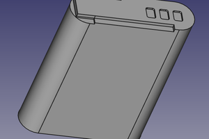
 MS-BOSS
great solution. Made 5 of them today. Very happy with them. Thanks.
Started working on a design for those 9V versions. So charge a Lipo and boost to 9V. Excellent idea.