Close
0%
0%

LRU

Scratching the itch of Least-Recently Used algorithms and topologies. I found something funny.

Similar projects worth following
LRU is an extension and modification of FIFO that is critical to cache replacement algorithms, sorting algorithms and compression algorithms (and by extension, crypto). It's important to both gather existing resources on this fundamental family of algorithms, as well as keep track of my own explorations and musings.
Pseudo-LRU is essential for CPU design and in April 2024 I discovered an interesting family of systems (algo/circuits), it looks like an interesting alternative to the other LRU algos I know.
So this project is where I document my explorations and collect interesting data.

Let's simply start with a simple algorithm pointed to by Wikipedia and that seems to have been widely used :

pseudo-LRU

two-way set associative - one bit

   indicates which line of the two has been reference more recently


four-way set associative - three bits

   each bit represents one branch point in a binary decision tree; let 1
   represent that the left side has been referenced more recently than the
   right side, and 0 vice-versa

              are all 4 lines valid?
                   /       \
                 yes        no, use an invalid line
                  |
                  |
                  |
             bit_0 == 0?            state | replace      ref to | next state
              /       \             ------+--------      -------+-----------
             y         n             00x  |  line_0      line_0 |    11_
            /           \            01x  |  line_1      line_1 |    10_
     bit_1 == 0?    bit_2 == 0?      1x0  |  line_2      line_2 |    0_1
       /    \          /    \        1x1  |  line_3      line_3 |    0_0
      y      n        y      n
     /        \      /        \        ('x' means       ('_' means unchanged)
   line_0  line_1  line_2  line_3      don't care)

   (see Figure 3-7, p. 3-18, in Intel Embedded Pentium Processor Family Dev.
    Manual, 1998, http://www.intel.com/design/intarch/manuals/273204.htm)


note that there is a 6-bit encoding for true LRU for four-way set associative

  bit 0: bank[1] more recently used than bank[0]
  bit 1: bank[2] more recently used than bank[0]
  bit 2: bank[2] more recently used than bank[1]
  bit 3: bank[3] more recently used than bank[0]
  bit 4: bank[3] more recently used than bank[1]
  bit 5: bank[3] more recently used than bank[2]

  this results in 24 valid bit patterns within the 64 possible bit patterns
  (4! possible valid traces for bank references)

  e.g., a trace of 0 1 2 3, where 0 is LRU and 3 is MRU, is encoded as 111111

  you can implement a state machine with a 256x6 ROM (6-bit state encoding
  appended with a 2-bit bank reference input will yield a new 6-bit state),
  and you can implement an LRU bank indicator with a 64x2 ROM

Of course the 1998 link on the Intel website has long been broken but this gives us a first approximation :

  • 2-sets uses 1 bit. This can't be more simple or easy and the logic is truly minimal. Go for it everytime you can :-)
  • 4-sets is more complex. There are only 3 bits if pseudo-LRU is good enough for you, but true LRU now has to be distinguished and grows as N!, so you'll need 6 bits and a 256-bits ROM.

How can one build larger systems ?

Wikipedia lists many strategies but it is desirable to get "most" of the true-LRU benefits without the size, time and costs.


Logs:
1. 4-LRU
2. 4-way Pseudo-LRU
3. PLRU4
4. MRU mode
5. The other LRU
6. MRU in L1
7. Hit or miss
8. More complete myLRU
9. .
10. .

.

.

DamienGille_cache_algo.pdf

Master thesis by Damien Gille, 2007, with a lot of very interesting data.

Adobe Portable Document Format - 1.64 MB - 09/14/2024 at 22:43

Preview

circuit-20240502-0227.circuitjs.txt

LRU+MRU interactive circuit

plain - 4.61 kB - 05/02/2024 at 00:27

Download

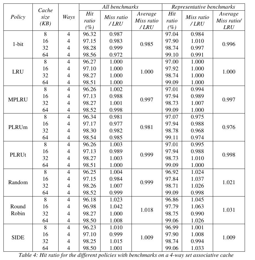
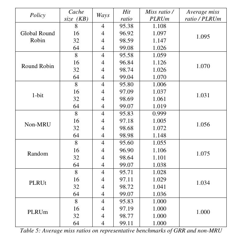
  • Some data from the Litterature

    Yann Guidon / YGDES09/14/2024 at 22:36 0 comments

     So @Kannagi  sent me a few references and failed to remember where they come from.

    Now, WHAT is PLRUm ?

    And are these numbers affected by the availability of L2 cache ?

    _______________________________

    Oh, that comes from Damien Gille's 2007 Masters thesis that I added to the "files" section.

  • More complete myLRU

    Yann Guidon / YGDES05/05/2024 at 11:15 0 comments

    Once again, by writing a log, I realise something I missed before. This new version of myLRU (I decided to give it a cute little egotistical name) is more complete now.

    I take the previous version and add 2 signals :

    • a HIT input flag
    • a WAY output field

    This only adds a few more gates and makes it easier to incorporate into a whole cache system.

    The HIT input enables the match/comparators, so spurious invalid inputs don't affect the LRU algorithm. It's only a matter of extending the NOR to 3 inputs.

    ......

    Yeah that was a bit premature. So here I start again from scratch:

    ....

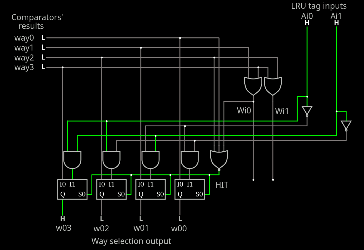
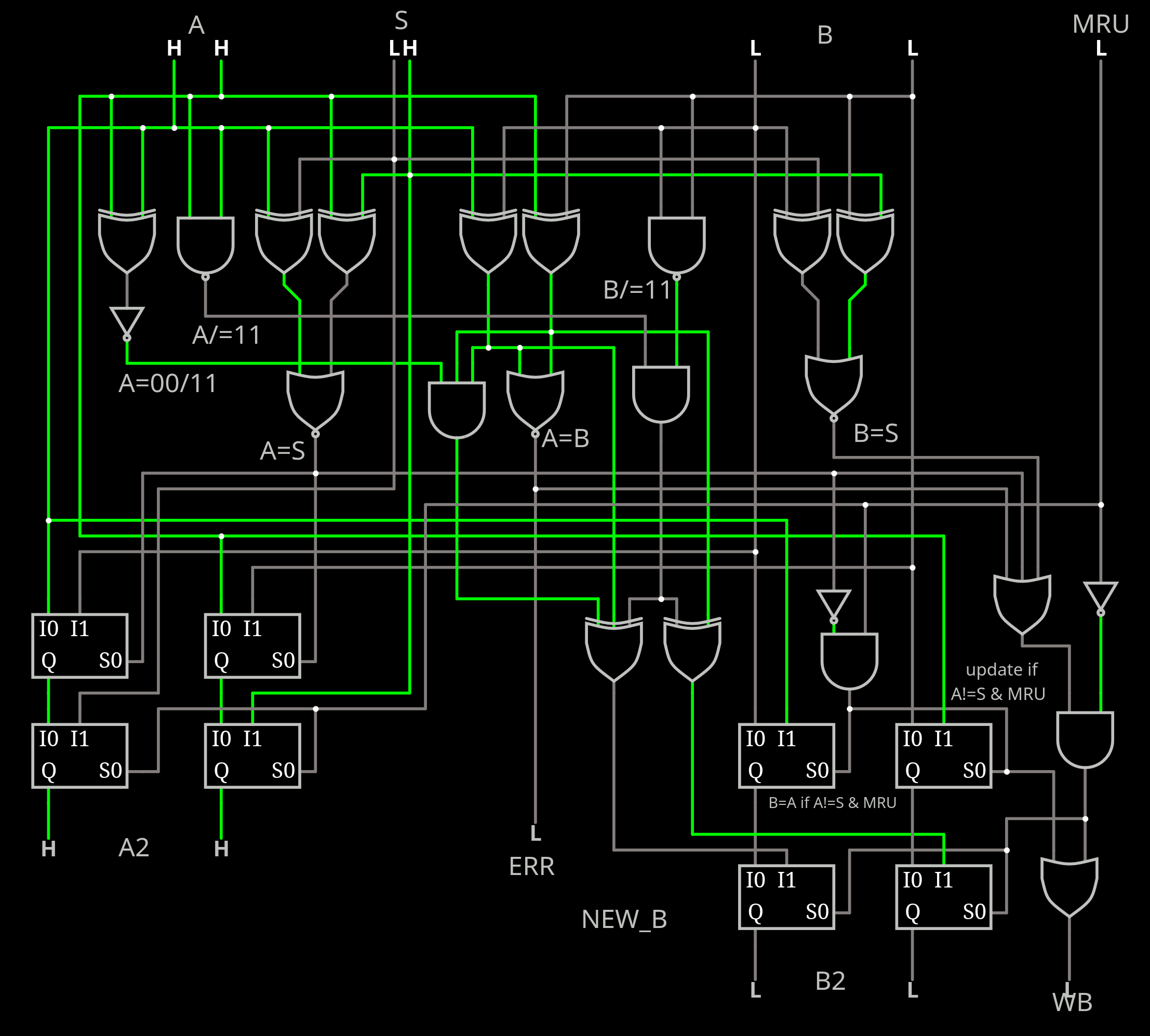
    In this circuit, the matching way is encoded to 2 bits and fed to LRU circuit that works in parallel.

    • If there is a hit, the "way selector" output is a copy of the input (no need to change it).
    • If there is a miss, the "way selector" output is A decoded.

    Meanwhile,

    • if MRU is set, LRU will keep A and B as is
    • otherwise A<=B and B<=new_B

    ....

    So overall, there are 4 cases:

    1. A<=A, B<=B when MRU=0 & A!=W & B!=W (hit C or D)
    2. A<=A, B<=new_B when MRU=0 & B=W  (hit B)
    3. A<=B, B<=new_B when MRU=0 & B!=W  (hit A)
    4. A<=W, B<=A when MRU=1 & HIT=1 & A!=W

    Note: A=W and B=W is the error condition so there are only 3 relevant conditions for MRU=0, respectively:

    1. A!=W & B!=W
    2. A!=W & B=W
    3. A=W & B!=W

    This updates the previous list such that

    1. A<=A, B<=B when MRU=0 & A!=W & B!=W (hit C or D) or MRU=0 and A=W (hit A)
    2. A<=A,  B<=new_B when MRU=0 & A!=W & B=W  (hit B)
    3. A<=B, B<=new_B when MRU=0 & A=W & B!=W  (hit A)
    4. A<=W, B<=A when MRU=1 & HIT=1 & A!=W (hit B, C or D)

    .

    temporary playground.

    .

    The effect of HIT is not well defined for the MRU=0.

  • Hit or miss

    Yann Guidon / YGDES05/05/2024 at 01:52 0 comments

    The LRU and pseudo-LRU methods have a different behaviour, depending on the hit or miss event. The influence of read or write is not yet taken into account.

    Considering the ideal, true LRU : the tag bits are only updated if the last way is different than the MRU field. my LRU behaves this way too but with fewer fields to compare, hence fewer chances of update.

    The whole cache cycle is a 4-step dance:

    1. take a portion of the address bits to address one set of the cache, and read it all, latch it in a large buffer.
    2. compare the (4) address tag fields with the upper part of the desired address, encode the result down to 3 bits : 2 "way" bits (2× OR2) and 1 "hit" bit (OR4).
    3. LRU magic : the just read tag bits are mixed with the "way" bits to create new LRU tag bits.
    4. the eventual new data is sent along with an eventual new address to the selected way, and the LRU tag bits are updated for the whole set (when applicable).

    Note : here I don't consider the (unlikely) case of partial access. The whole line is used, 16 or 32 bytes at once.

    The link between 3 and 4 has some implicit assumptions that must be clarified. It all depends if there was a hit or miss, and read or write.

    ......

    to be continued

  • MRU in L1

    Yann Guidon / YGDES05/04/2024 at 15:11 0 comments

    I have seen that a lot of research has been done on enhancing the behaviour of L2 and L3 caches, in particular to prevent "thrashing", using deeper histories and complex replacement policies. I see little references on this subject concerning L1 and I have only found references to "minimising the LRU bits" which was a legitimate concern 30 years ago, but today... What's one more bit ?

    A better hit rate on L1 reduces the pressure on L2, which is often seen as a compromise to the weaknesses of L1. This is why MRU mode in L1 is interesting: it helps when thrashing is detected. But thrashing occurs between consecutive lines so the LRU bits of a given set can't do much...

    So a memory data read/write port must keep some statistics of the hit/miss ratios, miss sequences (a shift register ? resetable saturating register ?) and issue a LRU/MRU signal to the appropriate cache block. My algorithm (and pureLRU) can accommodate this and help with the reduction of thrashing.

  • The other LRU

    Yann Guidon / YGDES05/02/2024 at 19:49 0 comments

    If I want to be sure that my "invented here" LRU4 is both valid and better than other systems, I must compare them, which means I must also care for the existing systems.

    The first obvious choice is the IBM-invented 3-bit tree-LRU (as named and described in the wikipedia page). Which is actually a recursive version of the obvious 1-bit LRU for 2-way associative cache. You can't make simpler than that: it's an inverter!

    But for 4 ways, it gets a bit more complex, as quoted in the project description. Fortunately a sort of lookup table is provided:

    state | replace      ref to | next state
    ------+--------      -------+-----------
     00x  |  line_0      line_0 |    11_
     01x  |  line_1      line_1 |    10_
     1x0  |  line_2      line_2 |    0_1
     1x1  |  line_3      line_3 |    0_0
       ('x' means don't care)
       ('_' means unchanged)
    

     This can be condensed in a few gates:

    No wonder this is a favourite method, but is it actually good ? It seems this is out of fashion in the last 20 years.

    This is to be compared to the "true LRU", which uses 5 bits in the optimised case.

    An MRU mode could be implemented by not updating the bits.

    ------------------------------------------------------

    Another, more modern method (Itanium, SPARC...) is the 4-bit "bit-LRU" with a pretty weird scheme. Quoting Wikipedia:

    Bit-PLRU

    Bit-PLRU stores one status bit for each cache line. These bits are called MRU-bits. Every access to a line sets its MRU-bit to 1, indicating that the line was recently used.
    At this point, OK I get it, pretty simple and it makes sense: "mark the accessed way as it is used". But then, it is different because after a while, everything will be marked. The method here looks trivial but unheard of:

    Whenever the last remaining 0 bit of a set's status bits is set to 1, all other bits are reset to 0.
    WHAT ? you just clear the whole history ???

    So far this is the corresponding circuit:

    At cache misses, the leftmost line whose MRU-bit is 0 is replaced.

    There is a priority encoder now? why not a random value to prevent biases ?

    This increases the logic depth, unless a ROM is used. The priority encoder is added below:

    This circuit provides both the binary encoded number of the new set to replace, as well as the 4-bit set. The logic depth is 5 here (like the one I designed).

    And I'm not sure how to design a MRU mode with it.

    Maybe the trick for this system is to send 5 signals to the target line : 4 "set" signals, and one "reset all" signal (overdriven by the one set signal). Set-reset flip-flops take fewer transistors (one half) than DFF gates.

    The bias might be how, over time, some lines might get moved toward the "left" and create a sort of natural LRU where the "rightmost" are evicted more often but I have only vague ideas about it and it should be tested as well as documented.

    ---------------------------------------------------

    Update:

    I looked at the referenced paper from 2010, where it's called "NRU" (Not Recently Used) and the description is "slightly different" !

    So the position of the first candidate rotates, preventing a bias. Is the counter general, or stored with the lines ? The latter would take 2 more bits per line. And a counter is more "concerning" than a PRNG.

    ...............................................................................................................

    And since we're in 2024, power consumption matters, and in this case signal activity (level changes) have a significant importance.
    So the rate of changes must be included in the comparisons.

    Tree-LRU changes the polarity of 2 signals at every cycle ! (and only uses 8 of the possible 24 permutations).

    Bit-LRU might swap 4 bits at once from time to time, only setting one most of the time.

    ...............................................................................................................

    Another detail I seem to have missed is the Hit/Miss behaviour. That means another log about this subject...

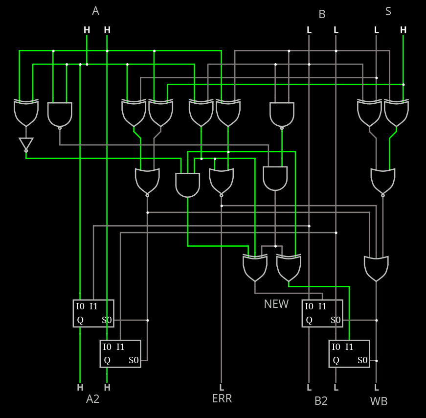
  • MRU mode

    Yann Guidon / YGDES04/30/2024 at 13:19 0 comments

    To implement on-the-fly MRU, it's simple:

    • if A!=S then B <= A (and enable update) (else B)
    • S goes to A.

    That's it.

    This takes precedence over the rest so adds a layer of MUX and some latency...

    .

    preliminary interactive playground here.

    .

    The added MUX layer is quite OK for the A output:

    A <= S when MRU='1'
      else B when A=S
         else A;

    Easy !

    But for B the equation is more complex.
    If MRU='1' then
      if A=S then
        B <= A;
      else
        B <= B;
      end if
    else
      if ... then
        B <= newB;
      else
        B <= B;
      end if;
    end if;
    

    This "folding" else is not obvious to redesign. Ideally only a pair of MUX2 should exist.
    And let's not forget the WB output.

    Here is another temporary version.

    .....

    But I have finally found a trick by swapping the MUX, giving more time for the decoding logic and reducing redundancies. The current version is there:

    The logic depth is about 5 gates and it supports both LRU and MRU modes. The approximate number of CMOS gates is 30, though going down to NOR/NAND logic could bring some enhancements, by sharing inverters for example.

    Can I consider the case closed ?

    I don't think so because I'll have to transcribe it to VHDL and then stress-test it with simulated worloads.

    That will come later :-P

  • PLRU4

    Yann Guidon / YGDES04/28/2024 at 18:51 0 comments

    I'm starting to play with circuitjs. You can try a first playground here. It's still buggy and incomplete but you get the idea of the actual complexity.

    For now I have dropped the requirement for B to avoid the 00 state, as well as the XOR. When the circuit detects A=B, it outputs an "error" status bit and forces the update: this makes the circuit self-correcting after a couple of cycles, like the old 4017.

    This changes the boolean equations that I already found the other night, and I must redesign them. There are only 64 cases to consider, with many possibilities, but few are minimal.

    The following lookup table shows the values injected into B, since A is usually a copy of the old B.

          |  S:
    A: B: |  00        01        10        11
    ------+-----------------------------------------
    00 00 |  R:01,10,11...........................
    00 01 |  A:10,11   B:10,11   x         x
    00 10 |  A:01,11   x         B:01,11   x
    00 11 |  A:01,10   x         x         B:01,10
    
    01 00 |  B:10,11   A:10,11   x         x
    01 01 |  R:00,10,11...........................
    01 10 |  x         A:00,11   B:00,11   x
    01 11 |  x         A:00,10   x         B:00,10
    
    10 00 |  B:01,11   x         A:01,11   x
    10 01 |  x         B:00,11   A:00,11   x
    10 10 |  R:00,01,11...........................
    10 11 |  x         x         A:00,01   x
    
    11 00 |  B:01,10   x         x         A:01,10
    11 01 |  x         B:00,10   x         A:00,10
    11 10 |  x         x         B:00,01   A:00,01
    11 11 |  R:00,01,10............................
    
    x : no modification
    R: error (A=B) =>      B=new (A=B implicit, harmless)
    A: Match A     => A=B, B=new
    B: Match B     =>      B=new
    

    In all cases, the output A is either input_A or input_B. So there is nothing to compute on this part.

    The only thing to compute is the new_B : 2 bits depending on 6 input bits. Make it 7 for the random input. And an 8th input for MRU mode but it doesn't affect the computation of new_B. And the table shows that the possible outputs only depend on the A and B inputs (4 bits only).

    Condensed array:

    A: B: A^B |  Possible values:
    ----------+------------------
    00 00  00 |     01,10,11
    00 01  01 |        10,11
    00 10  10 |     01,   11
    00 11  11 |     01,10
    
    01 00  01 |        10,11
    01 01  00 |  00,   10,11
    01 10  11 |  00,      11
    01 11  10 |  00,   10
    
    10 00  10 |     01,   11
    10 01  11 |  00,      11
    10 10  00 |  00,01,   11
    10 11  01 |  00,01
    
    11 00  11 |     01,10
    11 01  10 |  00,   10
    11 10  01 |  00,01
    11 11  00 |  00,01,10
    

    All entries have at least 2 possible outputs, to be selected by a random bit.

    The possible outputs must not be A or B so A^B is a very interesting value.

    The table shows that ~(A^B) is a valid value for most entries except for B=11, where A^B is valid, so we have something here! A NAND and a few XOR will work.

    Version 2 seems to not work correctly though:

    It seems that my initial boolean analysis was wrong.

    A: B: A^B /A^B |  Possible values:
    ---------------+---------------------
    00 00  00   11 |     01,10,11
    00 01  01   10 |        10,11
    00 10  10   01 |     01,   11
    00 11  11   00 |     01,10
    
    01 00  01   10 |        10,11
    01 01  00   11 |  00,   10,11
    01 10  11   00 |  00,      11
    01 11  10   01 |  00,   10
    
    10 00  10   01 |     01,   11
    10 01  11   00 |  00,      11
    10 10  00   11 |  00,01,   11
    10 11  01   10 |  00,01
    
    11 00  11   00 |     01,10
    11 01  10   01 |  00,   10
    11 10  01   10 |  00,01
    11 11  00   11 |  00,01,10
    

    There is obviously a requirement to use a "diagonal" of the squares (even permuted) because focusing on a column would create an unacceptable bias of the sequences, particularly if 11 is constantly output (except 00 when A=11). So both bits should be inverted when A!=11.
    But there is more happening with B=11 that requires special care.

    In the new circuit, A=00 B=11 and A=11 B=00 both resolve to the unwanted value 11.

    For A=00 B=11 this creates the forbidden state 11 11 when the desired set S is also 11. This case is only 1/4th and the result can later be recovered because the next state will become 11 00. Adding an extra gate can avoid the copy of B into A2.

    For A=11 B=00, the forbidden state 11 11 is also output when S=00.

    A few more gates (A[0] xor A[1], NAND3 and XOR3 replacing XOR2) solves this and we get :

    • A=00 B=11 S=00 => A2=11, B2=01
    • A=11 B=00 S=11 => A2=00, B2=01

    And that's it.

    A: B: | value:
    ------+---------
    00 00 |  11
    00 01 |  10
    00 10...
    Read more »

  • 4-way Pseudo-LRU

    Yann Guidon / YGDES04/28/2024 at 16:23 0 comments

    The last post was the first ever in this project, which was created about 3 years ago as a placeholder, I just wanted to keep track of interesting algos and have fun with them. I didn't expect to stumble upon what I just described... So I start to take it more seriously, not a one-white-night curiosity.

    As always, the goal is to get a fairly good replacement behaviour with the least resources and latency. I found something with a good ratio: at 4 bits of history, it's 1 more bit than the IBM tree-PLRU used in the 486 and others, but this is not a significant overhead, because you'll need 2 more MESI bits per line. So 4 ways require (2*4)+4=12 bits per set of ways, instead of 11, no big deal here. And it's not far from the ideal 5.

    The decoding can be done with logic gates only, no ROM required. And it can be simply switched from LRU to MRU on the fly (by forcing a hit on a field).

    The algo only compares one half of the ways : that's just 2×2 bits to compare. And it compares only the ones to be soon evicted, leaving the uncertainty to the MRU half. So there are fewer bad surprises about lines that get evicted too early : there are at least 2 turns before it happens.

    I also like that it is scalable and easily configured. Higher numbers of ways can be handled with little effort, since only one half of the fields are compared.

    It is also energy efficient since repeated hits on the MRU half do not change the state: thus it is not needed to rewrite it back. Extra energy is needed when actual replacement occurs.

    -o-O-0-O-o-

    The system is based on the ideal LRU queue. For N entries, there are N fields (A, B, C, D, E... from the LRU to the MRU) that act as a FIFO until it is full. Let's have an 8-deep queue with slots A to H containing a permutation of numbers 0 to 7, initialised in increasing order:

    input sequence: 0 1 2 3 4 5 6 7
    
          LRU                  MRU
    slot:  A  B  C  D  E  F  G  H
    val:   0  1  2  3  4  5  6  7

    When a new value is added from the sequence, it is inserted at the MRU level, and the other values are shifted down the queue, until the inserted value is found. For example let's add 2:

          LRU                  MRU
    slot:  A  B  C  D  E  F  G  H
    val:   0  1  3  4  5  6  7  2 <==insertion

    The value 2 is found at the slot C so all the values at the slots on the right move down one position, overwriting the 2, which is re-inserted at the MRU slot H.

    Here is the problem:

    • The comparisons and shifting get heavy very fast as the queue depth increases.
    • We only care about the LRU field because this is the one we need to replace an old entry.

    Here is the solution:

    Only keep the M least recently used slots.

    For example, for N=8, we can set M to 3. This requires 3×3 bits&comparisons for the queue. This means that during replacement, a given entry must not appear M times to be evicted.

    The other beauty is that neither N or M need to be a power of 2. A 5-deep would require 6 bits of history since the

    • A needs 5 values
    • B needs 4 values
    • C needs 3 values

    B is encoded in 2 bits, A and C are encoded together in 4 bits because 5×3=15.

    Here is the new problem:

    Since the MRU slots are ignored, during shifting there must be one new value inserted. The value could be random but must not be one of the inputs. This is a less trivial question but it is still limited since only log2(N) bits must be "guessed". The wide range of possible values make it a good candidate for boolean simplifications (where creativity can be unleashed). The guess only depends on the existing  M×log2(N) inputs, not on the desired/matching set.

    • For N=4 M=2 it requires a 16×2 lookup and 2×2 comparisons.
    • For N=8 M=3, there is a 512×3 lookup and 3×3 comparisons.
    • For N=8 M=4, there is a 4096×3 lookup and 4×3 comparisons.

    Of course, some heuristics can further decrease the LUT size, using common boolean techniques.

  • 4-LRU

    Yann Guidon / YGDES04/28/2024 at 03:16 0 comments

    The permutation deamon is biting again, while I investigate a related caching subject. I am now considering the full LRU for 4 ways, using 5 bits arranged in 2-2-1 fields.

    Field A : 2 bits, it is a fully encoded (4 values from 00 to 11)  that directly points to the least recently used way. It is handy because the value is directly available.

    Field B : The middle 2-bit field has only 3 values, and 00 is forbidden (marks a cleared set). so the number of the 2nd-to-least recently used is a XOR with field A. The XOR is not required, after all, but not too heavy on the circuit anyway.

    Field C: 1 bit, selects which one of the 2 remaining sets comes first. The logic gets complex here, but now I wonder if that part matters at all. Maybe this field can be simply skipped and removed, because it does not affect the LRU much.

    In fact what matters is the least recently used, not the most recently used. So the first 2 can be skipped.

    All one has to do is compare a new set with the fields A and B, and if there is no match, no update.

    If there is a match then the matched field is replaced with the one on the left : this acts like a sort of shift register. And given the fields A and B, some boolean logic is enough to restore one of the missing set numbers.

    This greatly reduces the size of the LRU logic, probably as small as the IBM 3tree system but slightly better LRU behaviour. And there is no large lookup table as suggested in the project intro.

    ***************************************

    What's crazy is : while writing it, it all made sense and it was totally unexpected.

    Here is some pseudocode:

    A : 2 bits \ from LRU
    B : 2 bits /
    B' : 2 bits, is actual B.
    S : 2 bits (new set to update)
    A2, B2 : updated LRU fields.
    
    B' = A xor B;
    
    If S != A and S != B' : Do nothing.
    Else
       if S == A then
         A2 <= B
         B2 <= newB(A, B', S)
       else
         if S == B' then
           -- A is not modified
           B2 <= newB(A, B', S)
    

     So that's actually a few XOR and MUX.

    The secret sauce is in the function newB that creates the new value of B, which is derived from A, B' and S. This is used in both branches of the IF so we implicitely know that either S==A or S==B', as well as A!=B. A first approximation uses B, because it's already the difference which is never 0 ! (which could add a bias...)

    Here is the updated pseudo-VHDL code:

    B' := A xor B;
    newB := B;
    
    A2 <= B'          when  S == A               else A;
    B2 <= newB xor A2 when (S == A) or (S == B') else B;
    
    update if (S == A) or (S == B')
    

    The correct formula of B2 is not yet defined but you get the idea : it's quite simple. No weird LUT to precompute.

    newB can have two sets of values:

    • when B is 11, newB can be A^1, A^2, B^1 or B^2 (whichever you want),
    • when B is 01 or 10, newB can be /A or /B' (whichever you like),
    • B can't be 00 by the way. But if it is, let's set newB to /A2 to force a sane value.

    There is the risk that choosing only one field all the time (always A or always B) creates a bias that will disturb and affect the cache behaviour. This can be solved by using a 5th bit (resurrect field C) but that might be overkill so a random source is used.

    Some boolean simplifications could propagate through the circuit. At this point we do not really care that field B has only values 01, 10 or 11 so we spare some gates at the output. However B' =A^B is still required by newB.

    .

    Fun fact : this method can choose between LRU and MRU on the fly (for example if a stream is detected) by forcing a "hit" on field A (field B can have a match but will do the same as with A).

View all 9 project logs

Enjoy this project?

Share

Discussions

Yann Guidon / YGDES wrote 09/14/2024 at 22:02 point

The circuit seems to be small enough to nicely fit in a TinyTapeout tile :-) Who sponsors me ?

  Are you sure? yes | no

Yann Guidon / YGDES wrote 07/22/2024 at 10:48 point

TODO : include "lock" bits in the logic

  Are you sure? yes | no

Yann Guidon / YGDES wrote 04/28/2024 at 02:24 point

5-way seems easy :

2-way is 1 bit (easy).

3-way (6 permutations) requires 1+2 bits, with the 2-bit field using only 3 codes.

4-way (24) adds another 2-bit field, the new one is fully used.

5-way would require another 3-bit field that is not fully used. But we notice that 3×5=15, which fits in 4 bits. So the 3-bit field and the first 2-bit field can be merged.

So the 5-way full LRU permutations fit in 1+2+4=7 bits, which makes sense since 5!=120=2^7 - 8.

Interesting.

The remaining 8 codes can be used to indicate reset status for example.

  Are you sure? yes | no

Yann Guidon / YGDES wrote 09/06/2021 at 06:10 point

https://arxiv.org/abs/1512.00727 :

[Submitted on 2 Dec 2015 , last revised 3 Dec 2015 (this version, v2)]

TinyLFU: A Highly Efficient Cache Admission Policy

Gil Einziger, Roy Friedman, Ben Manes

This paper proposes to use a frequency based cache admission policy in order to boost the effectiveness of caches subject to skewed access distributions. Given a newly accessed item and an eviction candidate from the cache, our scheme decides, based on the recent access history, whether it is worth admitting the new item into the cache at the expense of the eviction candidate.

Realizing this concept is enabled through a novel approximate LFU structure called TinyLFU, which maintains an approximate representation of the access frequency of a large sample of recently accessed items. TinyLFU is very compact and light-weight as it builds upon Bloom filter theory.

We study the properties of TinyLFU through simulations of both synthetic workloads as well as multiple real traces from several sources. These simulations demonstrate the performance boost obtained by enhancing various replacement policies with the TinyLFU eviction policy. Also, a new combined replacement and eviction policy scheme nicknamed W-TinyLFU is presented. W-TinyLFU is demonstrated to obtain equal or better hit-ratios than other state of the art replacement policies on these traces. It is the only scheme to obtain such good results on all traces.

A much earlier and shorter version of this work appeared in the Euromicro PDP 2014 conference

  Are you sure? yes | no

Similar Projects

Does this project spark your interest?

Become a member to follow this project and never miss any updates