 Cees Meijer
-
1Housing
Print the housing, consisting of the Front, Mounting Frame and Backpanel, and print the buttons and D-Pad using a different color. All parts are available as .STL files in 'files' section as 'RPI_Handheld_STL Files.zip', or on Thingiverse: https://www.thingiverse.com/thing:4708101.
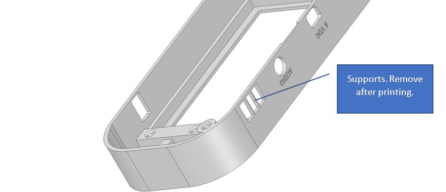
The size of the housing is such that it will exactly fit a 210x210 mm build plate, which is the standard for most 3D Printers. None of the parts will need support, and a layer height of 0.1 or 0.15 will give good results.
After printing the front section, remove the two vertical supports in the hole for the power switch.
![]()
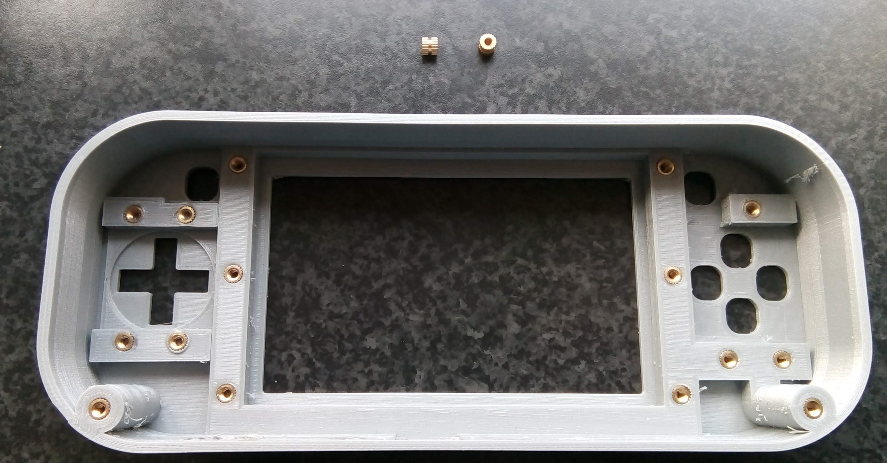
Insert the knurled nuts:
![]()
I used a soldering iron, set to 200 degrees and just slowly pushed in each nut.
-
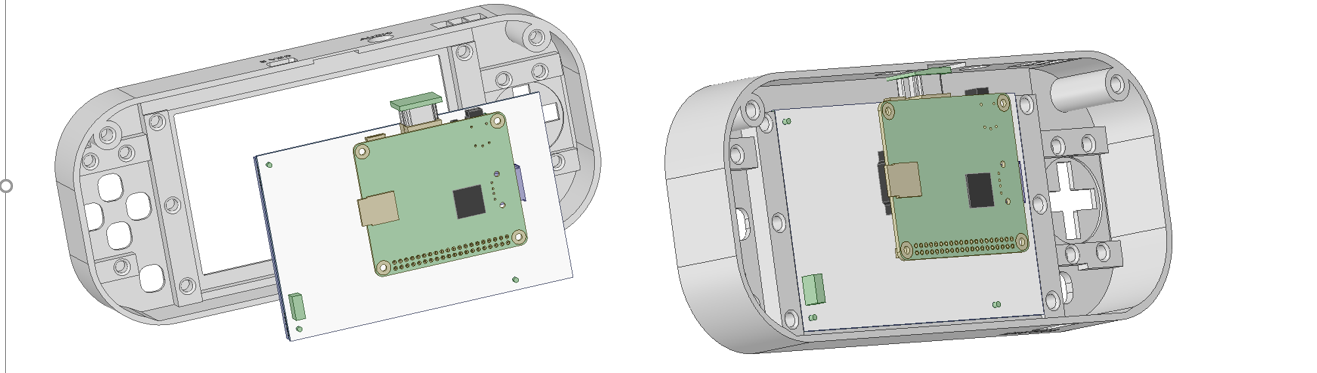
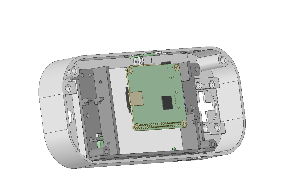
2Insert the Screen and Raspberry Pi
![]() Then fix the screen by adding the 'Mounting Frame'
Then fix the screen by adding the 'Mounting Frame'Use 2 or more M3x6 screws to fix the mounting frame.
-
3PCBs with switches
Use the 'PCBS With Switches Outlines.pdf' as a template and cut the perf-board for the switches.
![]()
The holes should be 3 ~ 3.5 mm. Note that the mounting holes are also on the 2.54 raster so it should be easy to drill them in the right position. ( the photo shows some extra holes, but that's because I re-used an old board) -
4Program the Arduino
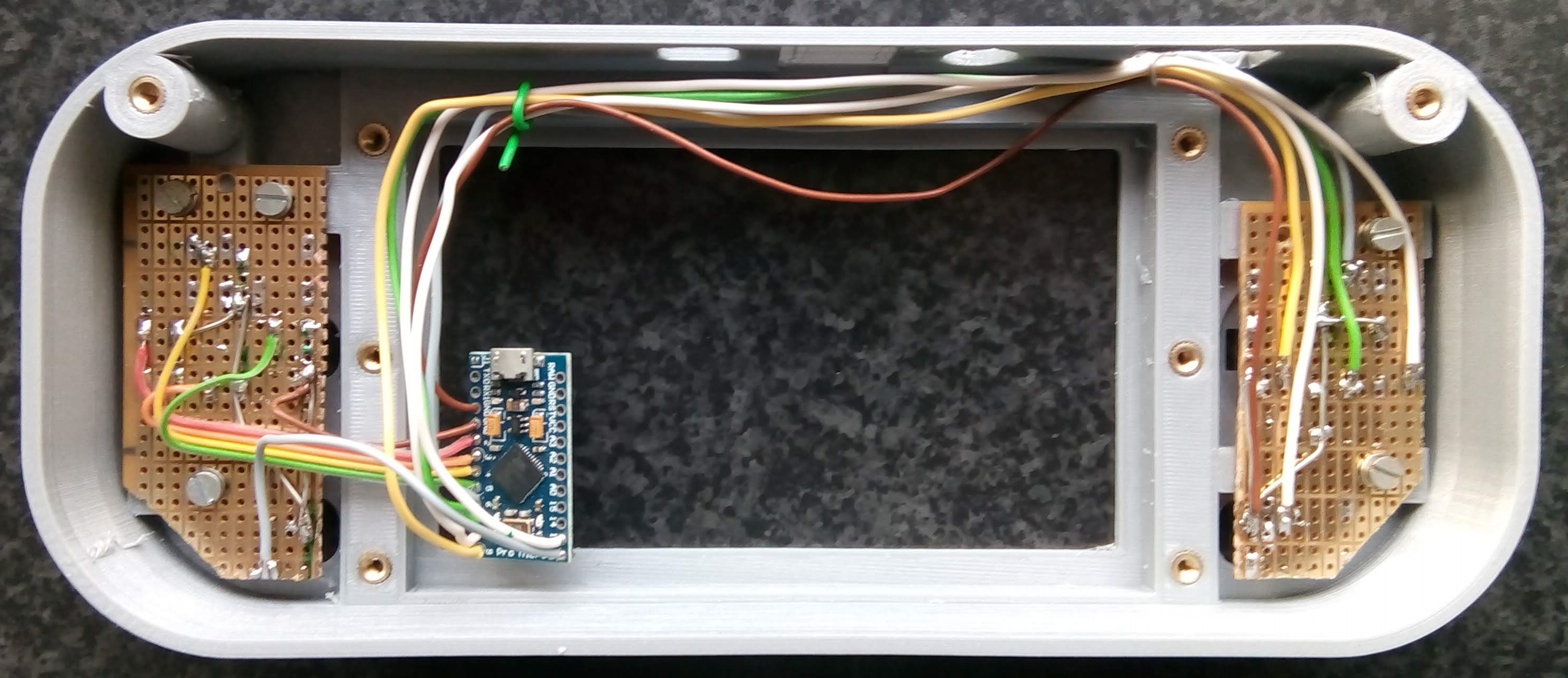
The controller uses an Arduino Pro Micro, 5V / 16 Mhz.
Before installing the controller 'sketch' you first have to install the gamepad library, which can be found in the GitHub repository of 'GAMELASTER':https://github.com/GAMELASTER/ArduinoGamepad
Download it by clicking the "Download ZIP" button on the right side.
Unzip the file, create a new directory named "Gamepad" in (typically located in Windows at) Documents > Arduino > libraries, and copy all files from "ArduinoGamepad-master" directory to that directory.
Then start a Arduino IDE and the library will appear in the list of libraries.Now download the 'GamePad_Simple.ino' sketch from the files section, and open it in the Arduino IDE.
MAKE SURE YOU SELECTED Arduino Pro Micro -> 5V/16Mhz VERSION !. (If you program it using the 3.3V/8Mhz setting, the Pro Micro will be bricked, and you can only recover it using the special procedure as described on the SparkFun site)
Program the Arduino.
-
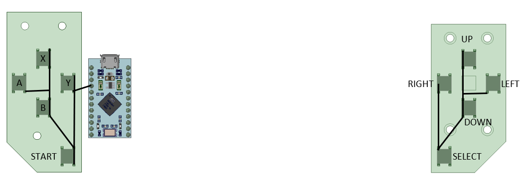
5Wiring the Switches to the Arduino
This image shows the PCBS from the back. The black lines show which contacts must be connected to GND:
![]() Next, connect all other sides of the switches to the Arduino Pro Micro. I used this image from the excellent 'Araymbox' instructions :
Next, connect all other sides of the switches to the Arduino Pro Micro. I used this image from the excellent 'Araymbox' instructions :![]()
Apart from the Select and Start button, nothing is connected on the right side since my design does not support shoulder buttons or an analog joystick.
(Sidenote: Though it's nice to have a schematic for the buttons, it actually does not matter how you connect them. The function of each button is assigned using the 'GamePad setup' screen in Retropie anyway.)
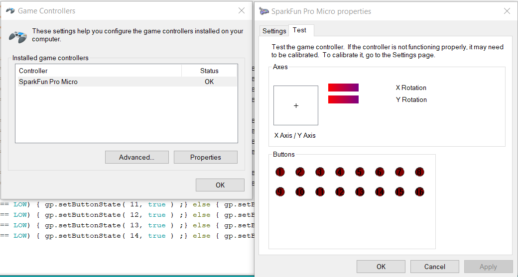
Now everything is connected, you can check the if it works.
- Connect the Arduino to your Windows PC using a USB cable.
- Windows should detect the Arduino board automatically.
- Press the WindowsKey+R to open the Run dialog.
- Enter "joy.cpl" and press Enter.
- Select the Arduino board and click Properties.
- Press any of your buttons and see if something happens in the Test tab.
![]()
Check all buttons. If some of them are not working check your wiring. If none of them work check the code. If the Arduino board itself is not recognized by Windows rewrite the code to the Arduino.
Place the buttons and D-Pad in the front, then fix the PCBs on top using some M3x6 screws.
![]()
-
6Power wiring
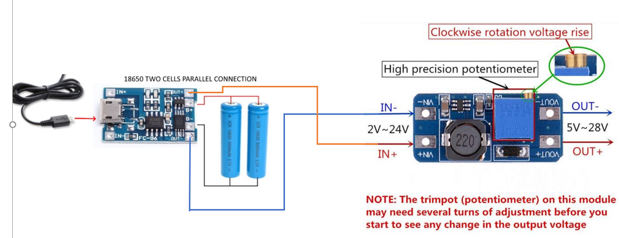
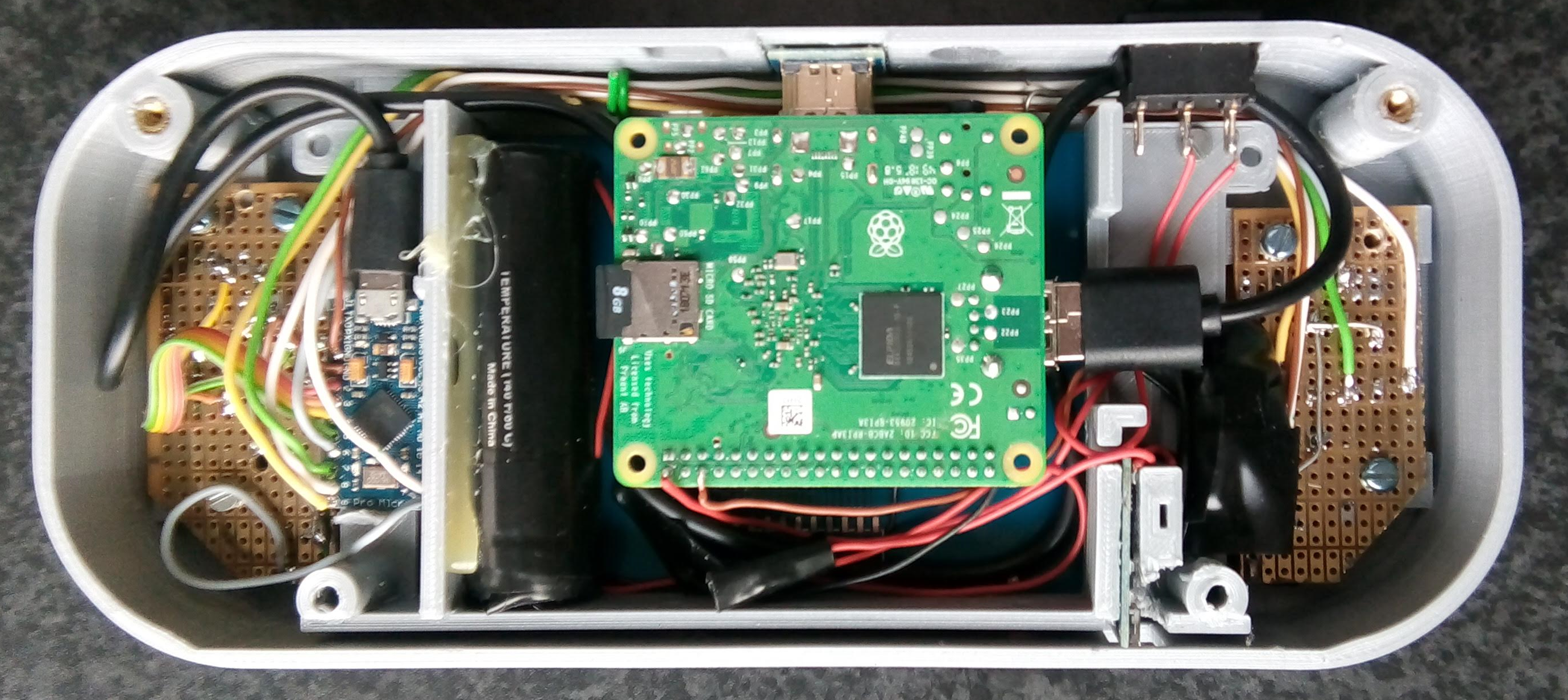
Power can come from one or two 18650 Li-Ion Cells. There is room for two cells in the design, but I noticed that it already runs quite some time on a single cell.
These must be connected to the TP4056 charger. The output of the charger now goes to the MT3608 boost converter.
![]()
There is no room for a battery holder, so the wires have to be soldered directly to the cells.
After connecting all this, first adjust the boost converter so the output voltage is close to, but not exceeding 5.2V. Anything higher than that will probably kill your Raspberry Pi and/or Arduino.
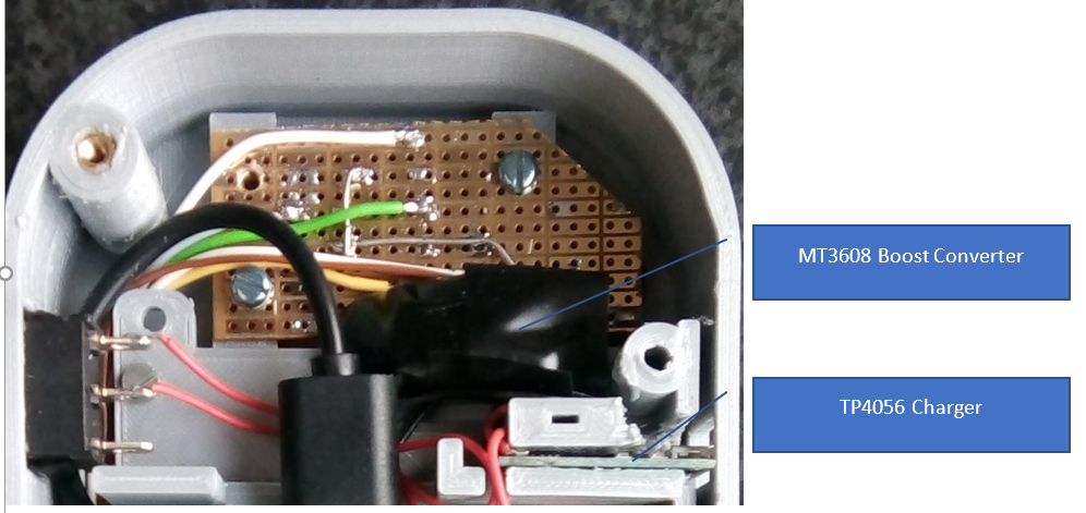
The charger must be at a specific location in the housing since the micro USB connector must be reachable from the outside.
![]()
Since the boost converter may come in different shapes or sizes, it is best just to wrap this in tape and let it hang loose, or fix it using hot-glue.
Wire the positive output of the boost converter to the switch and, and from the switch directly to pin 2 of the Raspberry Pi. The negative output from the converter can go to pin 4 or 6.
![]()
Raspberry Pi GPIO connector as seen from the rear ![]()
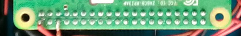
Careful soldering on the back of the Pi Check if the system powers up, and put the battery or batteries in place using hot-glue. Note that If you glue them to the mounting frame only it will be easier to disassemble the system later.
-
7Final steps
If you have not done so yet, install RetroPie on the Pi. Instructions can be found here:
https://retropie.org.uk/docs/First-Installation/
When installing you probably have the keyboard connected, and this is a good moment to set a new password, enable Wifi, and enable SSH on the Pi so you can make a wireless connection later. After booting the system with RetroPie, it will show a screen saying that there is no gampad connected, and you can F4 to exit. Press F4, and on te command line use 'sudo raspi-config' to open the configuration screen.
First enable the WiFi.:
- Select 'System Options'
- Select 'WIreless LAN'
- Enter the SSID and passphrase for your network
Then, while still in System Options, change your Password ! The default is 'raspberry', and you can be sure that at least 10% of the worlds population knows this!
Next, enable SSH:
- Select 'Interfacing Options'.
- Select the P2 SSH option on the list.
- Select <Yes> on the “Would you like the SSH server to be enabled?” prompt.
Now, get some games (...). And put them on the system, using a USB stick:
https://retropie.org.uk/docs/Transferring-Roms/
Connect the Arduino to the Raspberry Pi using a (short) USB A to Micro cable.
![]()
Close the housing by screwing on the back-panel. This can be done using 2 pcs M3x6 screws and 2 pcs M3 x 12.
 Then fix the screen by adding the 'Mounting Frame'
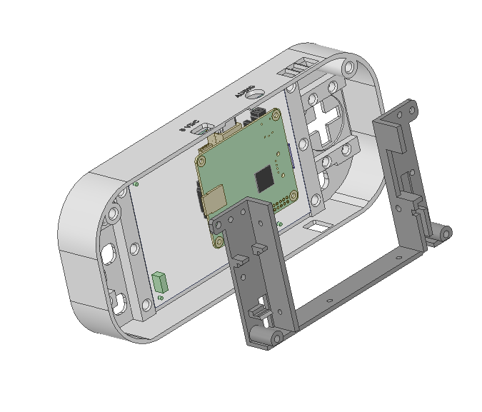
 Use 2 or more M3x6 screws to fix the mounting frame.
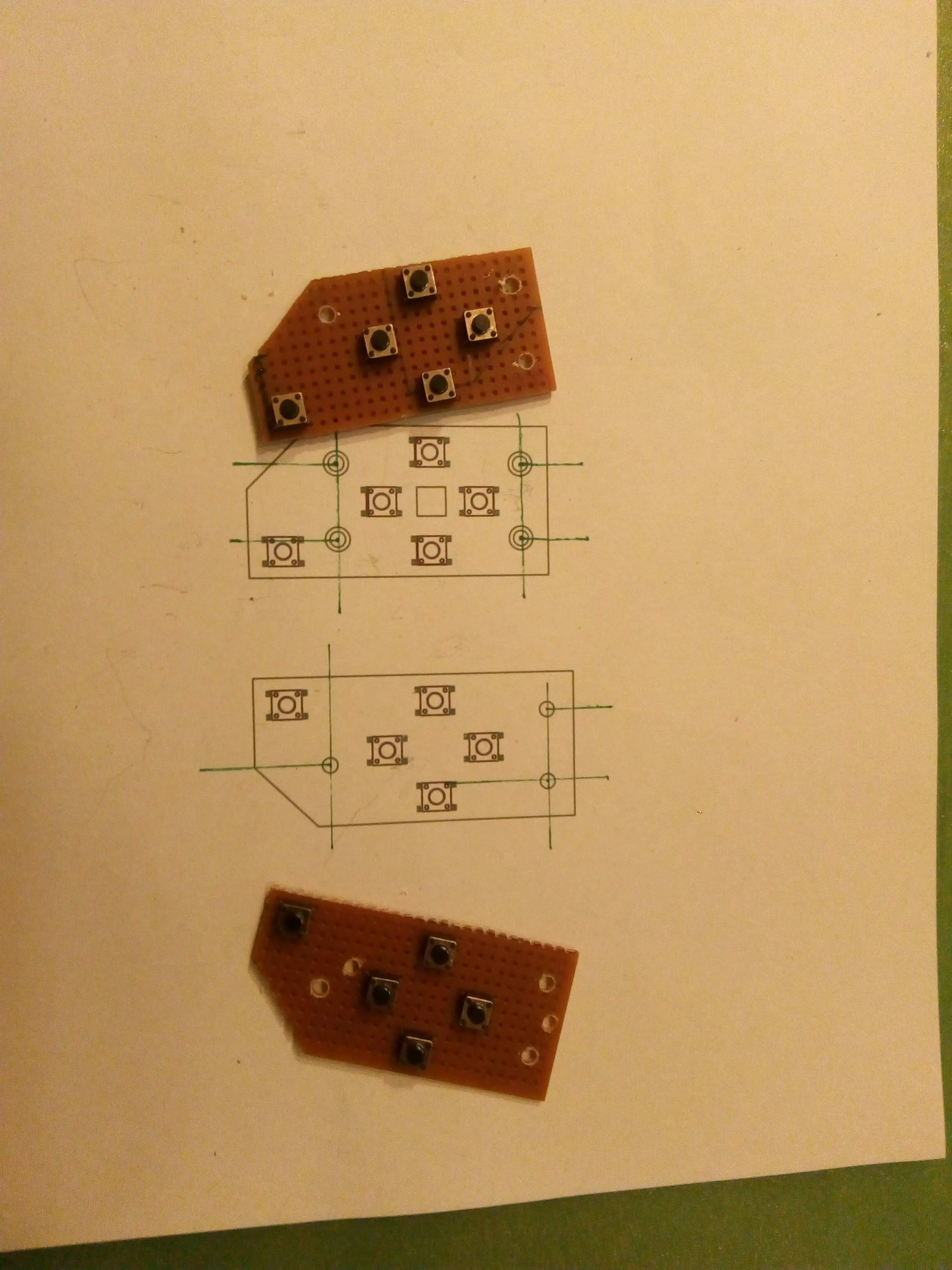
 Next, connect all other sides of the switches to the Arduino Pro Micro. I used this image from the excellent
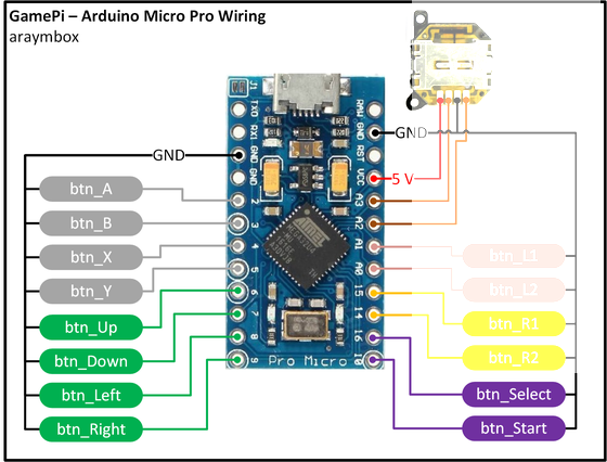
 Wire the positive output of the boost converter to the switch and, and from the switch directly to pin 2 of the Raspberry Pi. The negative output from the converter can go to pin 4 or 6.
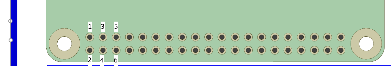
Discussions
Become a Hackaday.io Member
Create an account to leave a comment. Already have an account? Log In.