jackal123uk
-
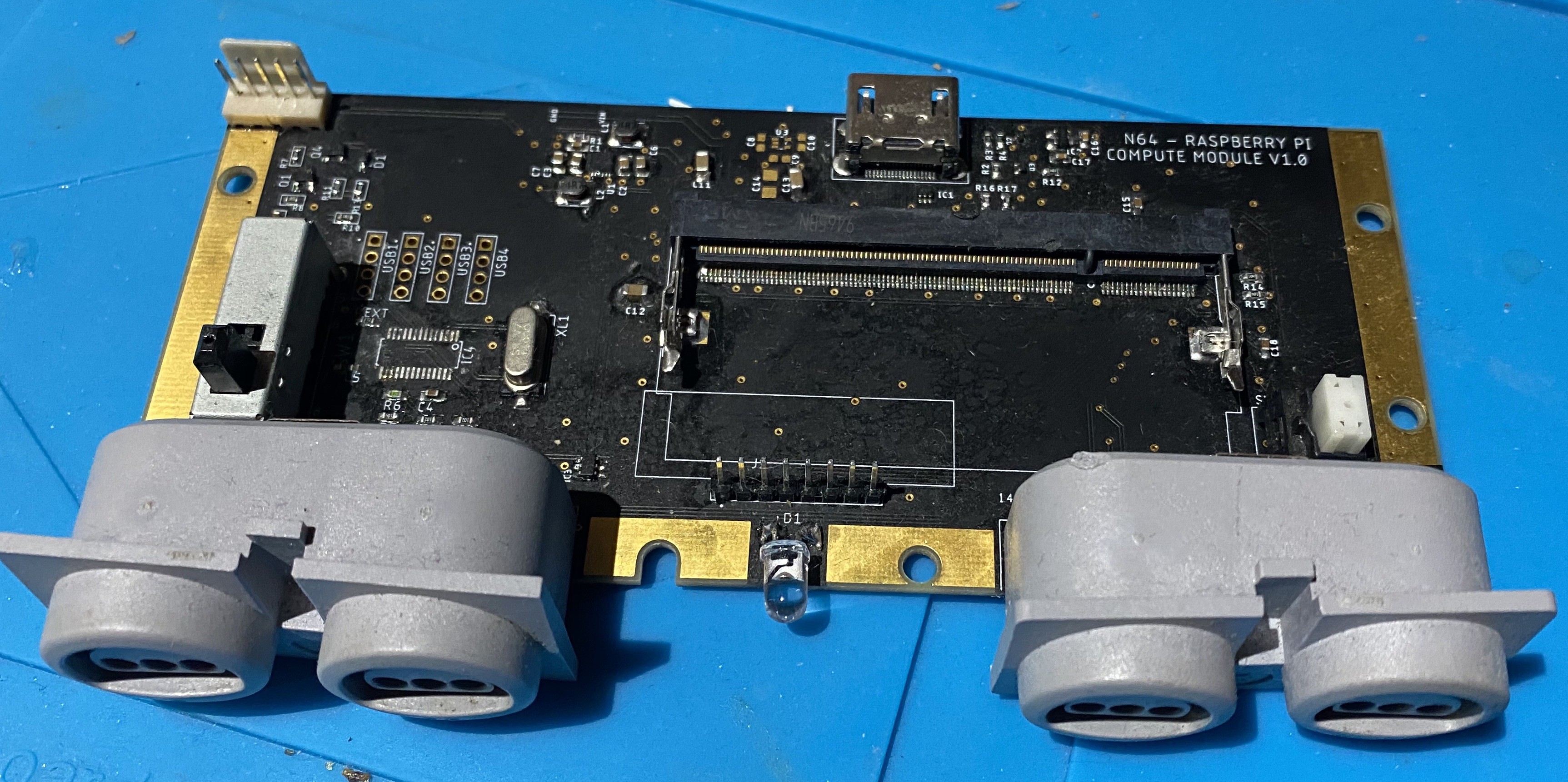
Assembly - The hardest part so far...
01/17/2021 at 18:22 • 0 commentsThe original components from the N64 are all through-hole so no major problems here except some of the tolerances are a bit tight. Maybe my measurements were off or maybe some old solder left on the pins - either way, any future revision will have the holes opened up slightly.
The fine pitch SMD components (especially to SO-DIMM connector) are another story. I used solder paste and a hot air gun for this - needed so cleaning up after but got there eventually.

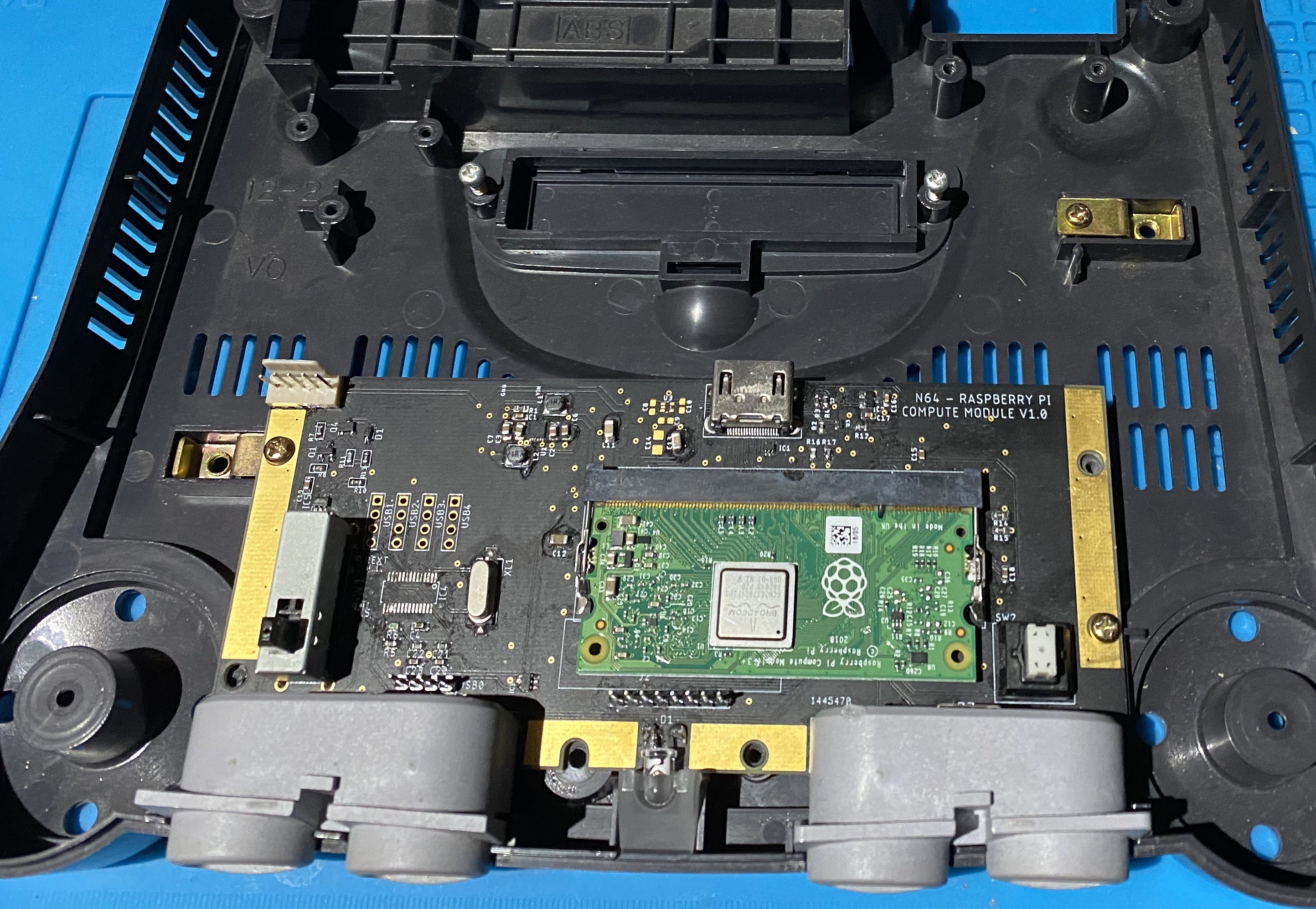
Good to see the the finished article fits perfectly into the shell too. A couple of things come to mind at this point - I should have mounted the compute module the other way round so that the Raspberry Pi logo was the right way up and if only the compute modules were also available in matte black...
Testing next; this should be fun
-
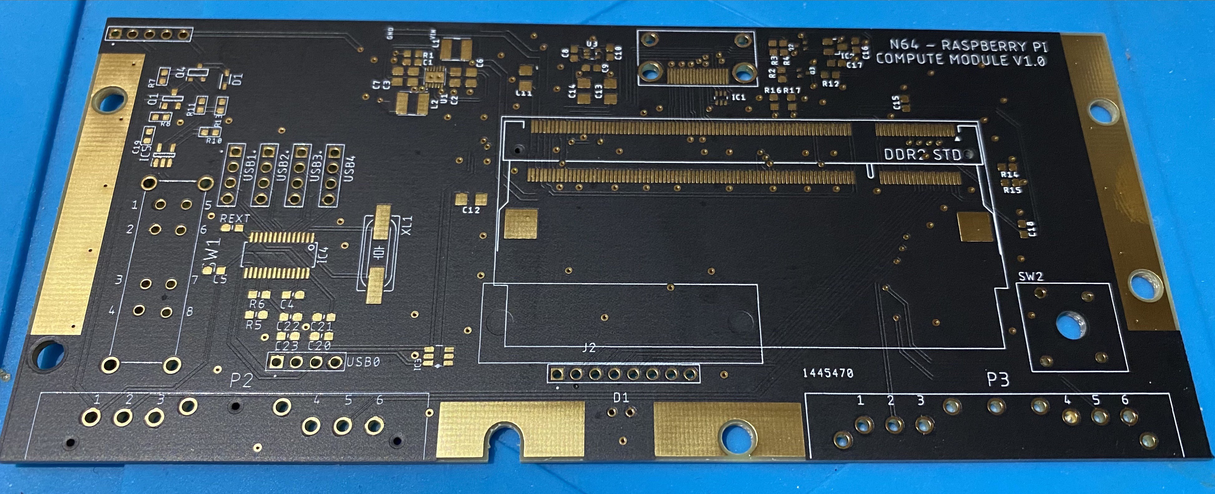
Fabricated Board
01/11/2021 at 20:58 • 0 commentsThat's the board back from the fabricators. I used Seeed Studio, I've used them a few times now - the prices are pretty reasonable if you don't mind waiting on the shipping from China.
I normally go for the bog standard green and HASL finish but I thought I'd try the matte black and ENIG - glad I did as it looks amazing!
-
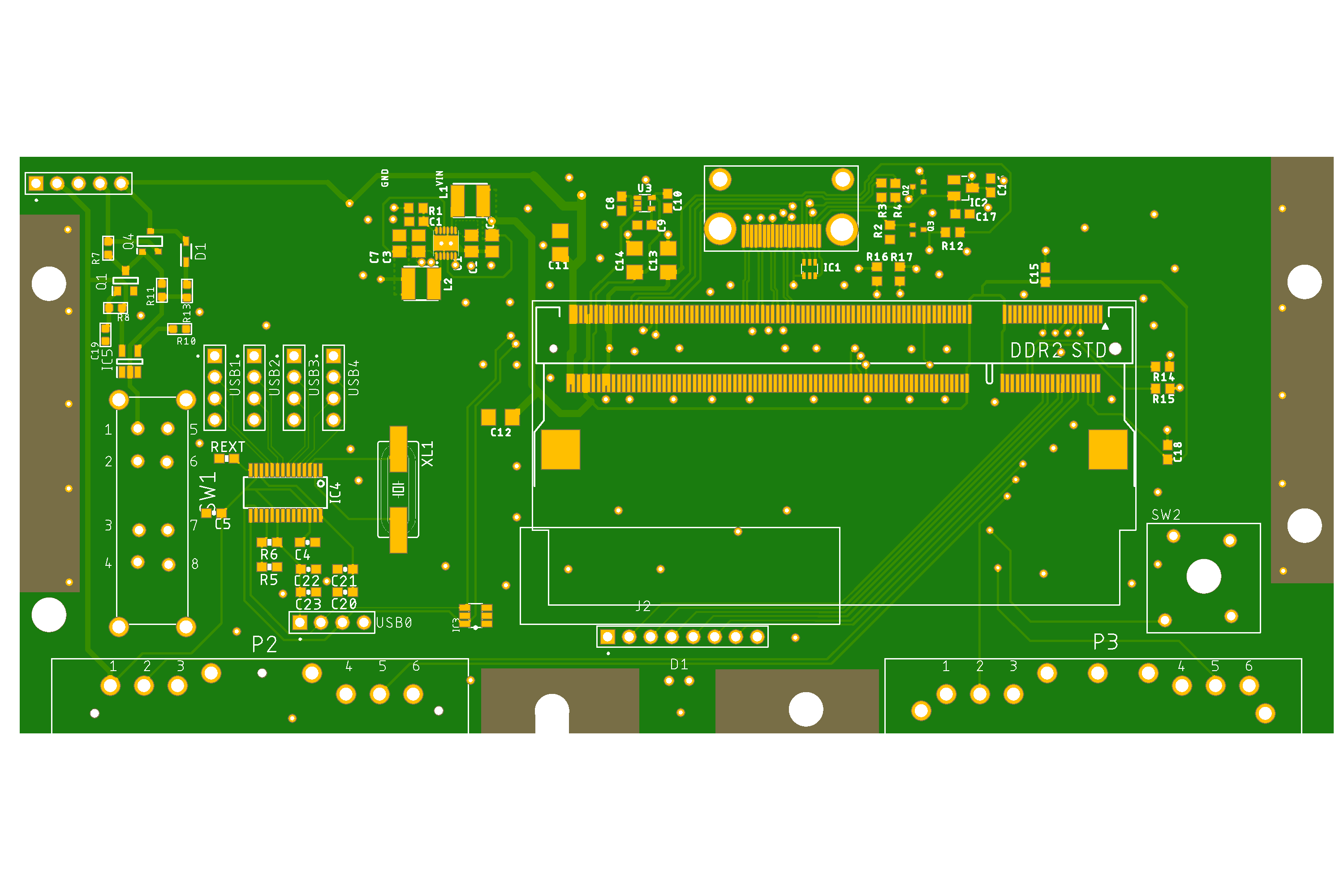
The Main Board
01/06/2021 at 21:43 • 0 commentsI redesigned the board in Eagle - I'll upload the SCH/BRD files once I've tidied them up, just bear in mind it's still very much a work in progress.
Note the following:
- footprints for all the original hardware (controller ports, power and reset buttons)
- power input headers at the top left - inputs for all voltages are included to allow for testing without installing the power regulator (just left of centre)
- USB hub circuit to the left side of the board - left as headers to give some flexibility in where to run the USB ports to (most likely under the cartridge flap)
- headers for connection to SD card breakout board - the regular compute module with eMMC can be used without this but needed for the compute module lite. Again, undecided on where to physically run the SD card socket to but hiding under the memory expansion cover is a likely candidate, hence where the headers are.
- Full sized HDMI port used (top, just right of centre) mostly for convenience when testing (and I have a stock of them left over from a previous project). I'll use a short extension to bring this out to natural N64 AV port.
-
Power Supply
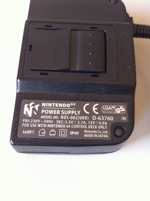
01/05/2021 at 23:45 • 0 commentsTurning toward the power supply it's easy to see that stock unit is supplied with 12V and 3.3V which is not fully compatible with the requirements of the compute module - namely 5V, 3.3V and 1.8V.
Strictly speaking you can run the compute module with only 3.3V and 1.8V but 5V is needed for HDMI and USB.
Since I've successfully used a circuit based around a PAM2306 regulator in the past I'll plan on using this to supply everything from a 5V source. As I don't like playing with mains voltages I might hide a standard (read safe) 5V charger inside the power brick.
-
Starting at the beginning...
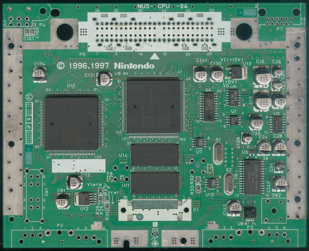
01/05/2021 at 23:16 • 0 commentsFirst thing first, we need to see what we're playing with here and how much room we have to work our magic.
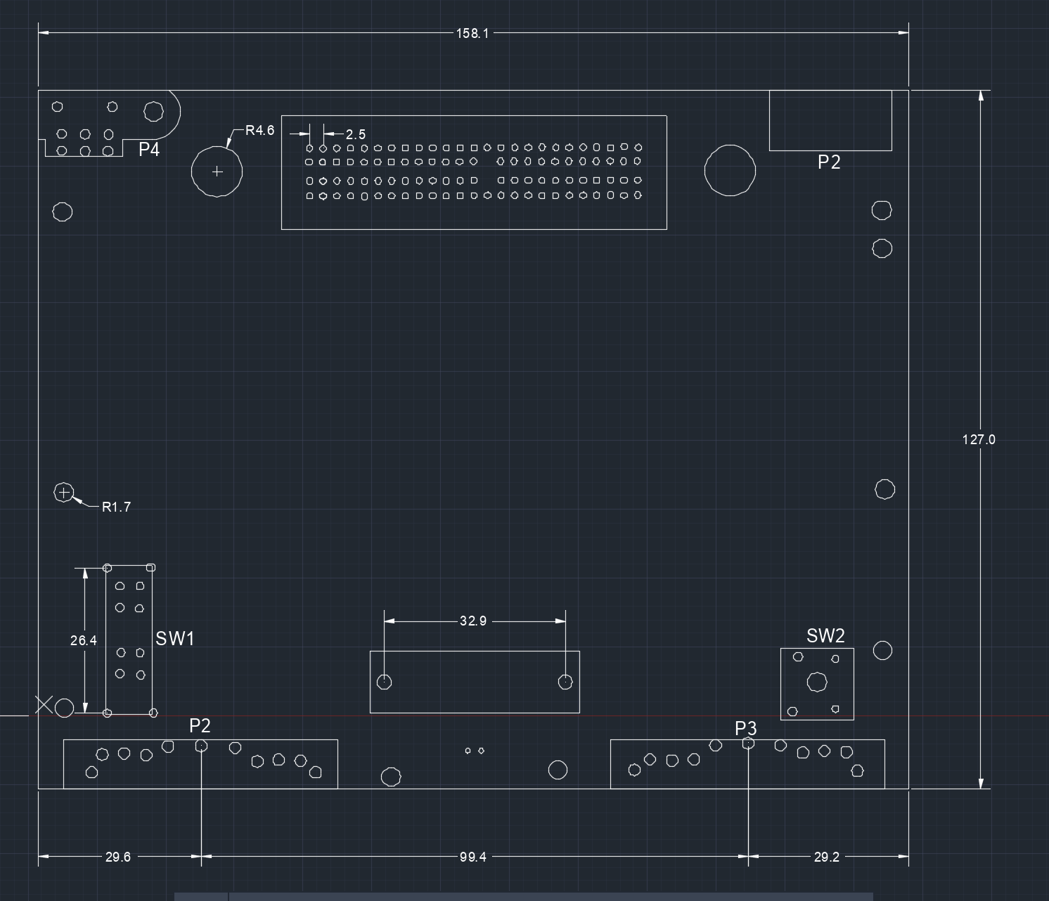
Since the plan is to reuse many of the original components (thereby keeping them in situ) we have to work around these. I attacked an original mainboard with some digital callipers to get the below (DWG/DXF versions in the files section).
N64 Raspberry Pi Retro Emulation System
Giving an N64 a new lease of life with a Raspberry Pi Compute Module 3