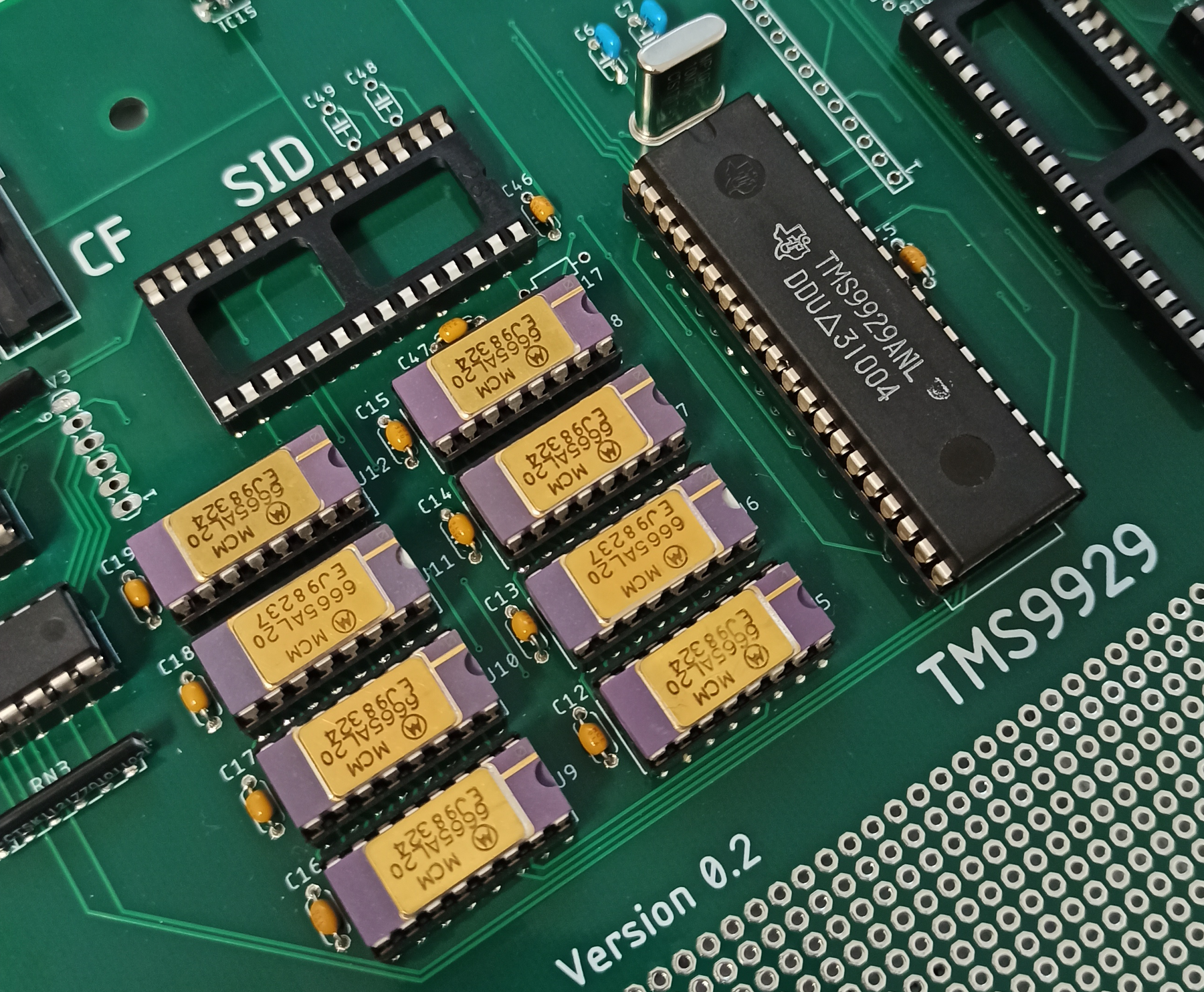
Anyway, a bit skeptic I started to do the acetone test.... All good, none of the paint came off. While doing this I also noticed a small molded Texas Instruments logotype in one of the blank circles on the top of the device which made me feel even better. You can se it in picture if you look closely.
Now for the real test. Would I get the 10.73 MHz oscillator running ? (drum-roll)
YES !! it works. A clean oscillator signal is present at pin 40 (If you want to measure this signal accurately do not measure the signal on pin 39. The capacitance of the probe will affect the oscillator and show you an incorrect frequency). The frequency is coming in a bit high at 10.739 but this is easily correct by adjusting C6 and C7. A trimmer cap would have been handy here but it won't take to long to tune the values.
 Second stage of the testing was to install the DRAM's and make sure that I can write data and read it back properly. So I wrote a short test program that wrote a test pattern to the memory and verified that it would read back properly. I let the program run for a few hours and no errors were found during this time. I also verified all the setup and hold time parameters with an oscilloscope, just to put my mind at ease. The VDP seem to perform significantly better than specified which means the timing margins are very good.
The DRAM's that I use are new old stock that I have been holding on to for decades. During the summer of 1984 I was working for a company assembling cardiographic measuring machines. These machines had a big CPU board with an i8085 CPU and a bucket load of TTL's and IO devices. My job was to test the boards and install them into the machines. All main boards that failed tests were scrapped, no repairs were done. Every board had 128Kbyte (16 pcs) of these MCM6665AL20 and I was allowed to strip the DRAMs from these boards and take home. I have kept them all of these years knowing it would come in handy some day =).
Anyway, the conclusion for today is that the TMS9929ANL and the DRAM circuitry seem to be doing its thing. I haven't tested connecting a monitor to it yet so the verdict is still out.
The next step is to install the RGB modulator and start testing that part of the circuitry so stay tuned.
Discussions
Become a Hackaday.io Member
Create an account to leave a comment. Already have an account? Log In.