Overview
The Gameboy Player accessory allowed Gamecube owners to play Gameboy Advance, Gameboy Color and Gameboy games via their console. It connected via the accessory port and a boot disc provided the software to allow the Gamecube to interface with it, providing control, video and audio output.
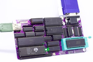
Inside the Gameboy Player
For my project I'm working with a European (UK) version. Opening up the case revealed a single PCB, shielded with metal casing. My board is marked as DOL-GBS-20. I've seen photos of boards marked DOL-GBS-01 and DOL-GBS-10 which are slightly different; for this project I'll only be describing information and modifications for the DOL-GBS-20. They may not work if repeated on other board revisions.
There are three main areas of interest on the board. At the back is the Gamecube connector/interface, at front right are various voltage regulators and lastly at front left is the CPU and ancillary components.
The CPU (marked CPU AGB A) on the bottom of the board is the same as the CPU in the original Gameboy Advance. There's a supporting SRAM chip, link port and of course the game slot.
The board naturally lacks other normal GBA components such as the screen, buttons and speaker. There also isn't a clock crystal directly connected to the CPU - more on this later.
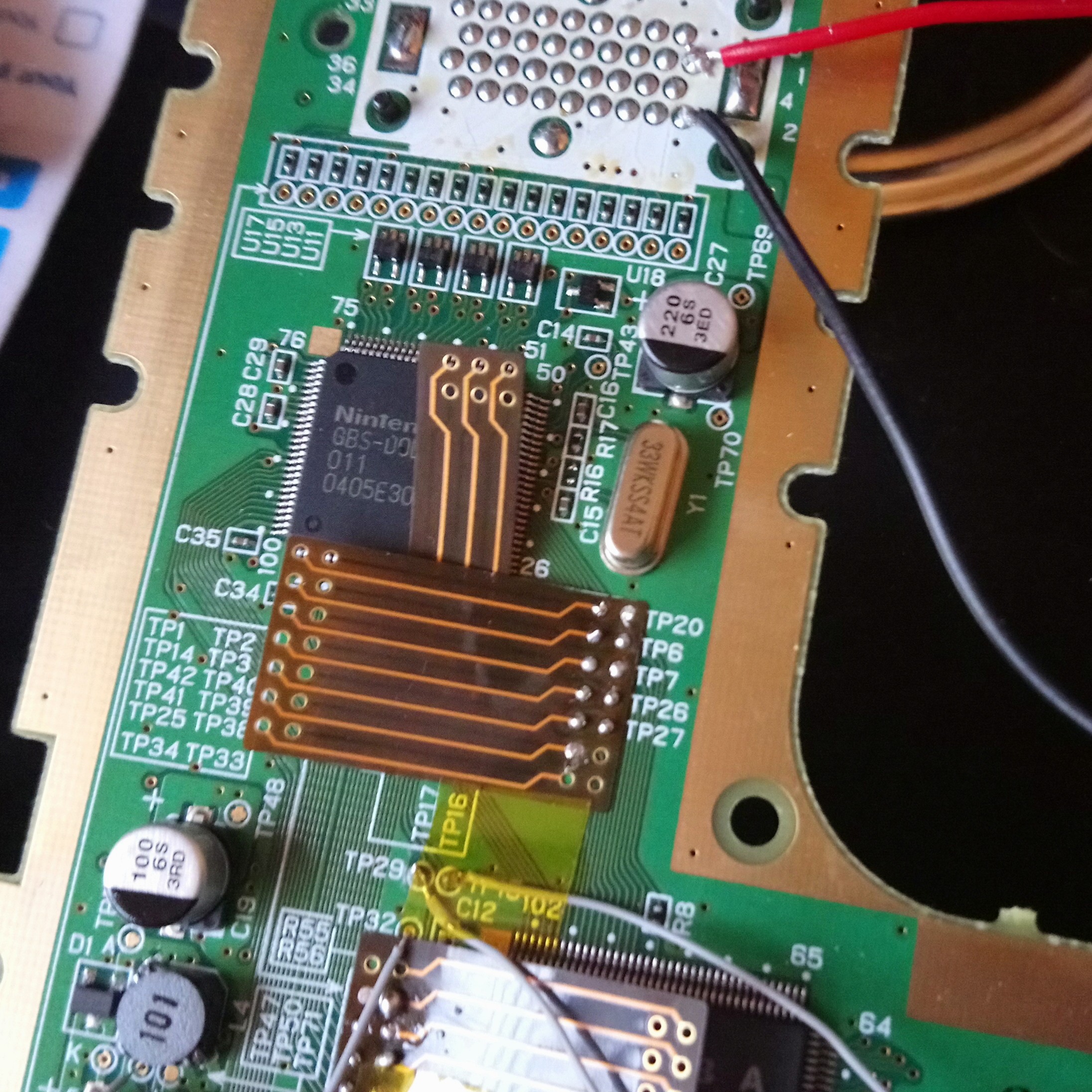
The interface takes up the job of communicating between the Gamecube and the GBA CPU. This area is dominated by the GBS-DOL chip which on one side connects to the Gamecube port and on the other to the pins of the GBA CPU. In theory GBS-DOL emulates the screen, button and speaker circuitry, passing control inputs from the Gamecube and returning audio/visual data to be processed by the Gamecube.
Finally the power zone regulates power to the interface and GBA zones.
Options for taking the Gamecube out of the loop
There are two ways to achieving this that sprang to mind. The first is to emulate the Gamecube through the interface port with some kind of microcontroller. The second is to take GBS-DOL out of the loop as well and hook up control, audio and video circuitry directly to the GBA CPU. The latter seemed within my abilities.
Let there be light - or at least, power
The first thing I tackled was the power zone. There were test points for the various voltage lines, including the line for the interface zone and lines for the GBA zone. Analysing the board layout led me to believe the board was probably powered by 3.3V, as there were regulators for 2.5V and 5V but not 3.3V as needed by the GBA zone. Hooking up a 3.3V power supply to the board via Gamecube connector pin 1 and GND to connector pin 2 resulted in power to GBS-DOL but not the GBA zone.
After analysing the components and routing in the power zone, it appears that TP50 controls the power transistor and regulators for the GBA zone. I hooked up TP50 to 3.3V, checked the other power TPs and confirmed that the expected voltages were present - and thus the GBA zone should be 'switched on'. This means that GBS-DOL can turn just the GBA components on and off, and that I could do so too.
Test Point | Expected Voltage | Equivalent GBA voltage line |
TP46 | 3V | VDD3 |
TP47 | 5V | VDD5 |
TP48 | 2.5V | N/A (GBS-DOL VDD) |
TP49 | 2.5V | VDD2 |
TP51 | 3.3V | N/A (board VCC) |
Clock and control
One obvious missing component from the GBA zone is the clock crystal. Instead there is a clock crystal labelled 33WKSS4BT connected to GBS-DOL. This appears to be a 33.554432MHz Kinseki crystal, which is 8x the normal GBA crystal frequency. It's likely GBS-DOL does a clock division and outputs to the GBA CPU.
TP32 is connected to CK1 on the CPU and CK2 appears to be unconnected. With power to the board, there didn't appear to be a clock signal when hooked up to a basic logic analyser. This might not be the same for other board revisions - Mogi_codemasterv needed to lift the corresponding pin on GBS-DOL to hook up an external clock and get it working. Both of us are using a clock signal generated...
Read more »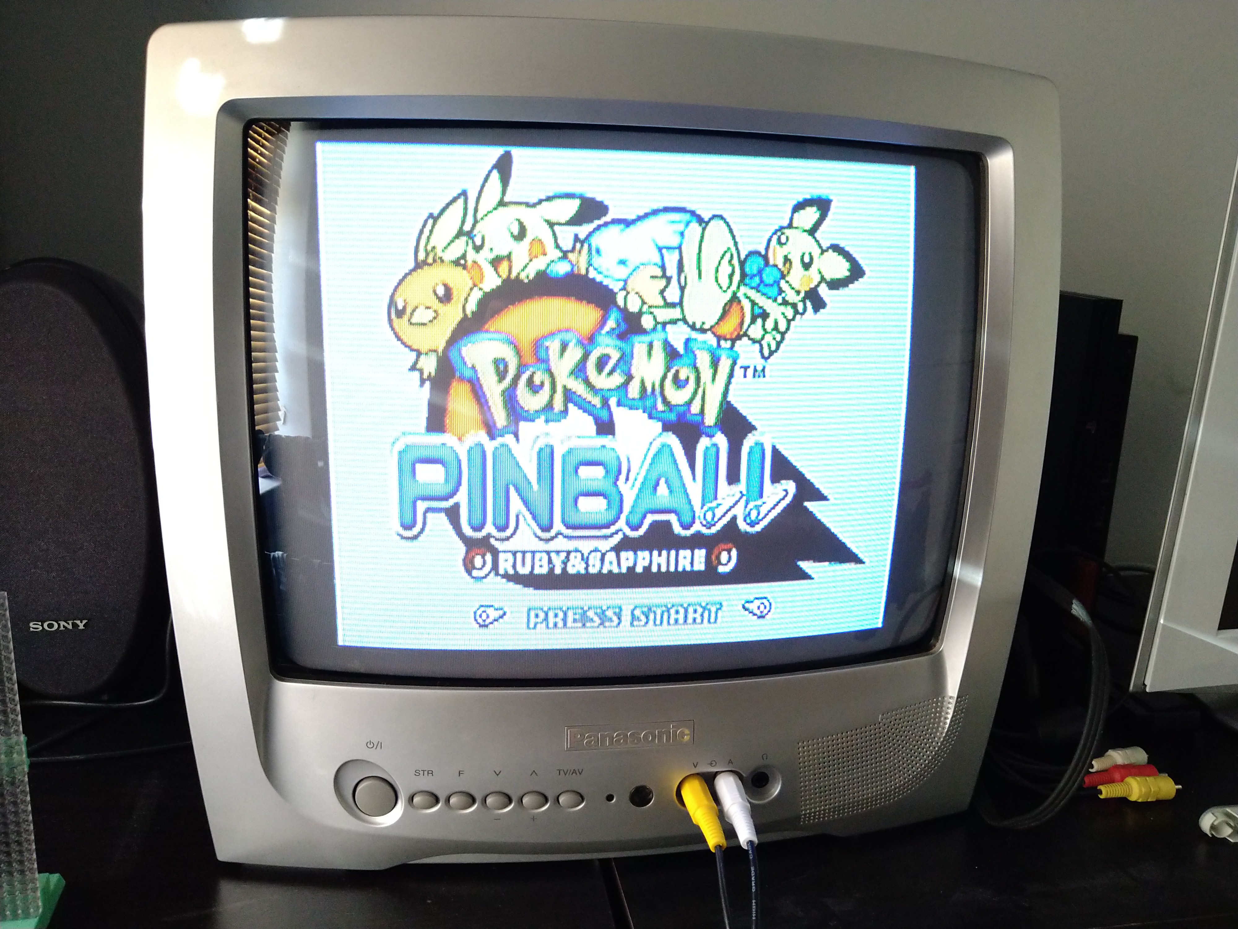
 carlni2008
 Oliver Scholz
 Anders Nielsen