But Why?
This project is the ultimate tool to combine general purpose modules to specific complex projects.
Some examples:
Inverted Pendulum:
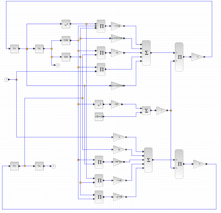
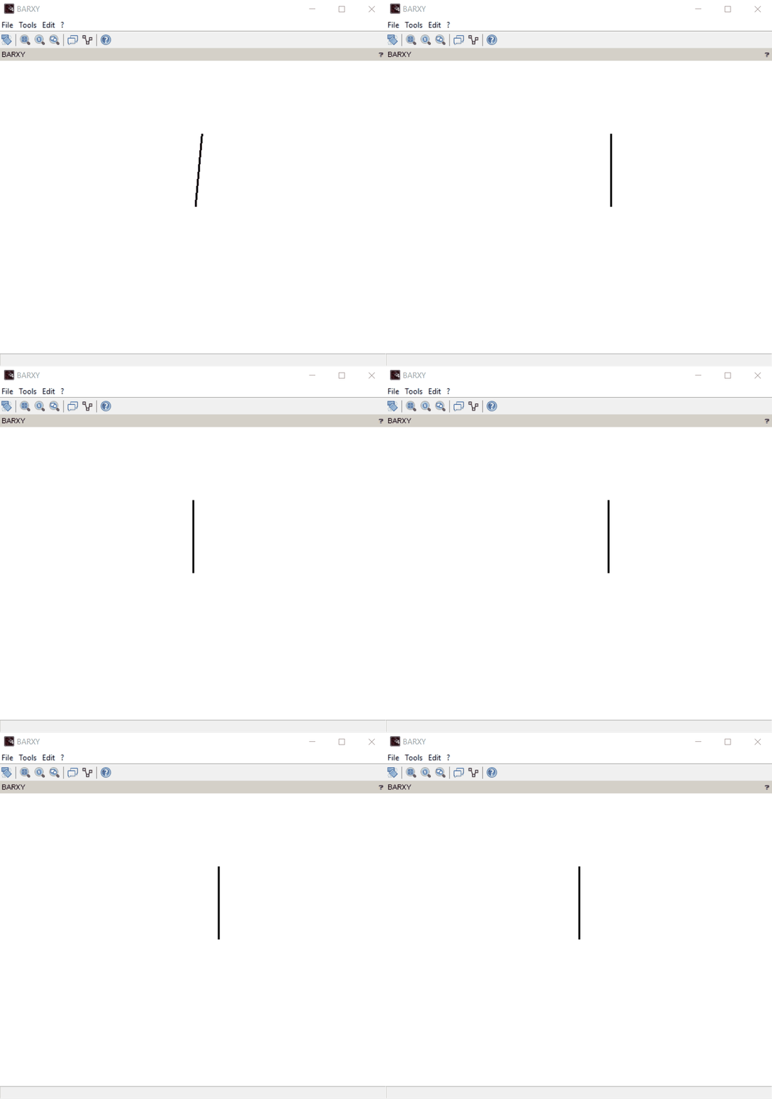
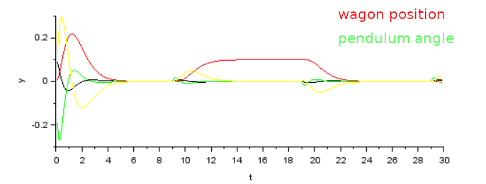
This is an actual example I work on at the moment, you can find details in the the project updates
You want to perform a basic controlling task such as controlling an inverted pendulum? Just grab the Analog Input Card to read out an optical encoder, and combine it with the Stepper Controller Card. Implement your control system using XCos, upload it to the FBus and there you go.
Oscilloscope:
You want to use an oscilloscope in your electronic project but not include it permanently? Just take the precision Analog Input Card, combine it with the HDMI Output Card and some auto-generated interface logic and voila - you have your oscilloscope.
CNC Motion Controller:
You want a CNC motion controller? Just hook up three Stepper Motor Controller Cards with the USB Interface Card, combine it with some control logic - you have your CNC motion controller.
Other ideas? Leave them in the comments! :-)
Planned Cards
To enable a wide range of projects to be implemented I plan to implenet a full range of daughter Cards enabling all kinds of control an measurement setups an non exhaustive list of cards I am working on or thinking about:
To make use of FBus in a wide range of controlling and measurement applications, I plan to build various daughter cards:
- Precision Analog Input and Output Card
- Fast Analog Input and Output Card
- Amplifier and Analog Frontend Cards
- General Purpose IO Card
- Logic Analyser Card
- HDMI In and Output Card
- Arduino compatible Card
- Stepper Motor Driver Card
- Brushless Motor Driver Card
- High Frequency Cards (like signal generators, counter, mixer)
- Any other ideas or wishes? Leave it in the comments!
The Components of the FBus
The Configurator
In order to allow dynamic configurations of all the parts of the bus we need to talk to all of them. This is the Job of the Configurator which will have one UART channel to each of the bus members to upload bitstreams, make firmware updates, or check for general health of the bus participant. It has one reserved Slot on each FBus backplane. It self does not act like a master of the bus as it has no access to the actual data lines. It will communicate to the outside world using an ethernet base protocol and is explicitly only for configuration purposes and can not perform realtime critical tasks.
The Bus
These are the slots where the actual functional Nodes are located. Each will usually contain an SymbiFlow-compatible FPGA and a small Microprocessor to load the bitstream for it. It taps into up to all of the 40 differential communication lines. But if it does not require that much data throughput it can just stick with one or two or just as many as are necessary.
The Timekeeper
The FBus is designed to be synchronous in order to guarantee hard realtime properties. Therefore there will be one timekeeper per backplane that contains a set of PLLs with the ability to phase adjust the clock for each Node so that all boards on the bus are perfectly in sync.
Specification
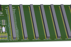
The FBus uses the physical PCI-e connector for connecting the Nodes and the Timekeeper and the Configurator with a backplane. In this first version the Lines are designated to allow differential routing on a two-layer backplane. The data part of the PCI-E connector contains 40 differential Data Lines, one differential clock line, a TX/RX UART channel, a 5V Supply, a system voltage supply (can be anything from 5V to 24V). In the supply part of the PCI-e connector are 16 general purpose lines intended for supply of analog...
Read more » flow
flow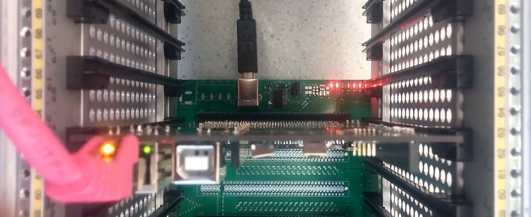
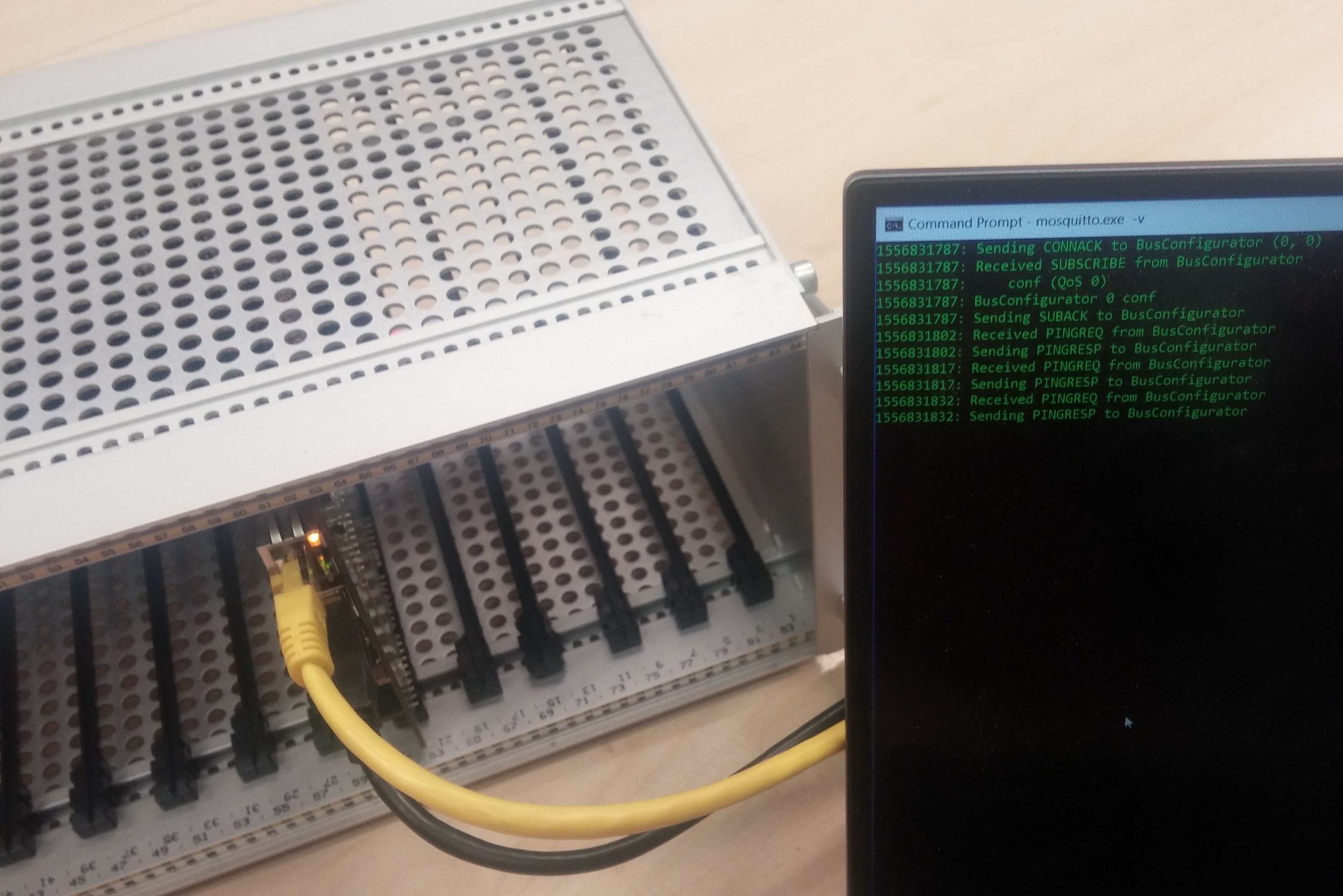 I finally managed to get the ethernet chip running i suspect that the crystal had a bad contact. From there on I managed with the help of the pubsubclient library to get the thing talking. Also I managed to score a really nice enclosure for the project on ebay.
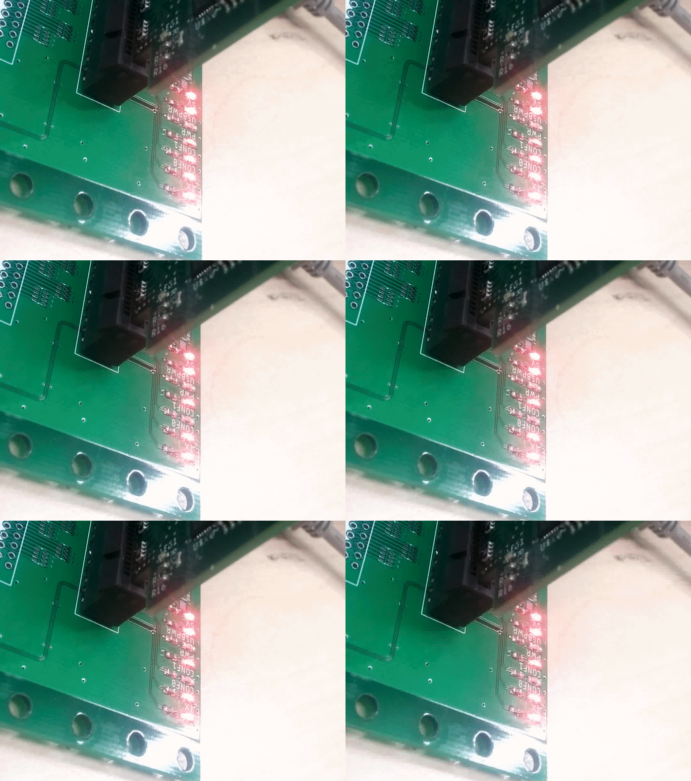
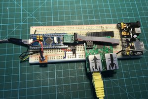
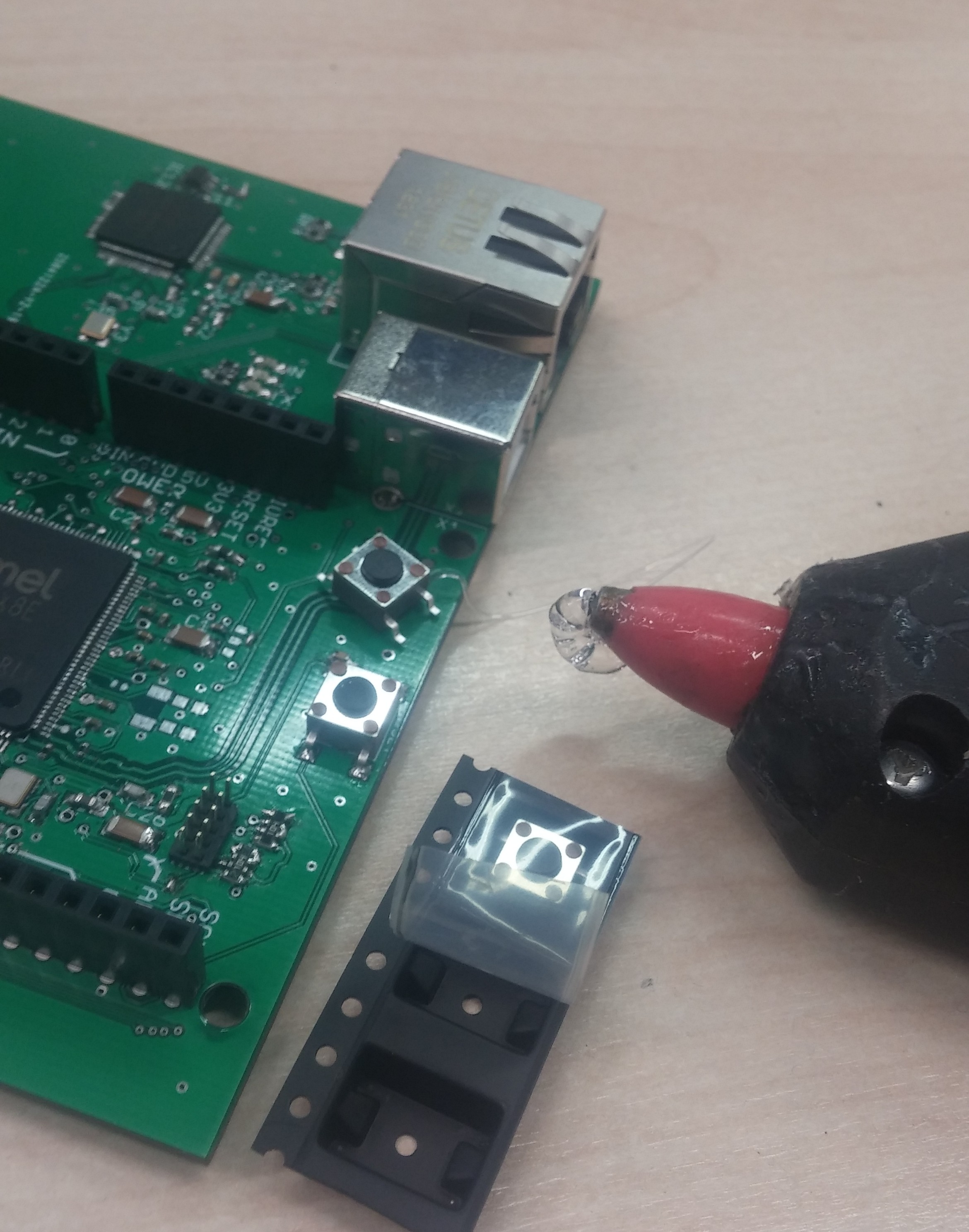 Now I am struggeling with the W5100 that I want to use for the ethernet communication and the upload of the bitstreams. The Oscillator doesn't start unless I touch the oscilator circuit with my finger. So I presume something is off with the capacitors. If somebody has debugged something like this before I would be happy about some pointers. (So far I never took to much care about Crystal resonators and they always worked out)
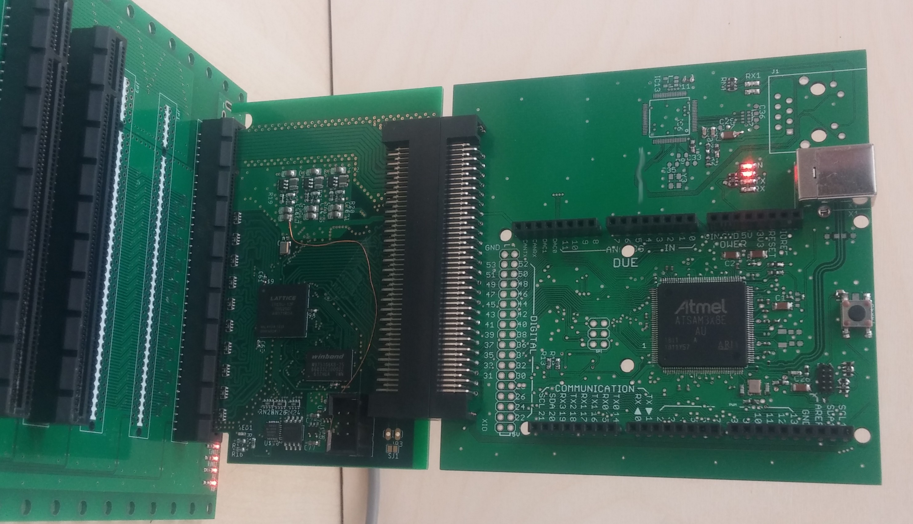



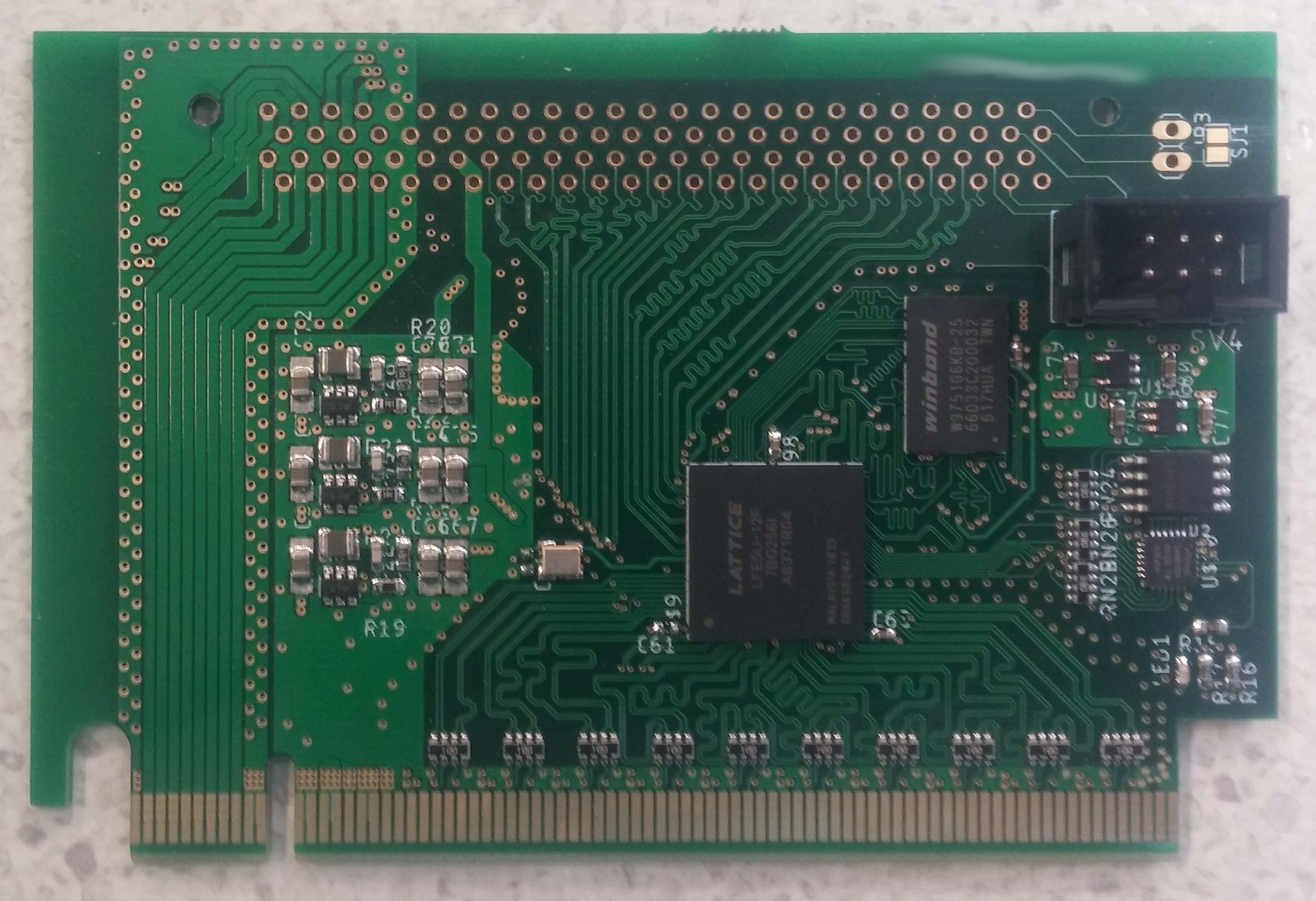
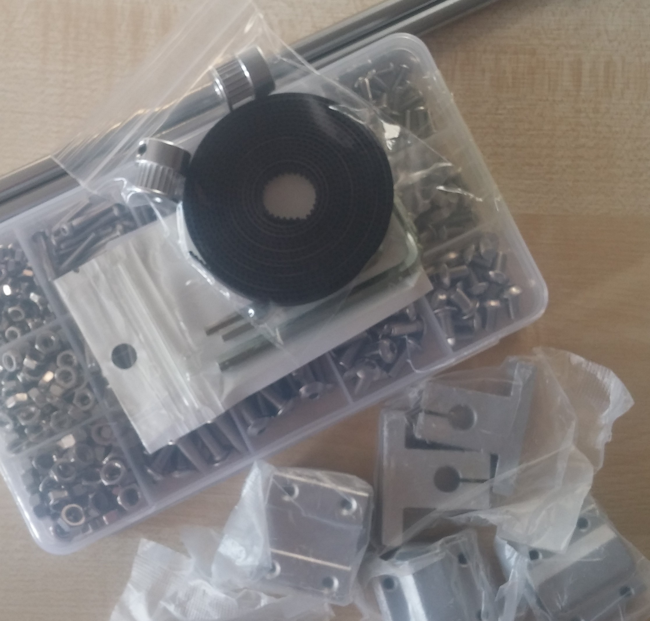
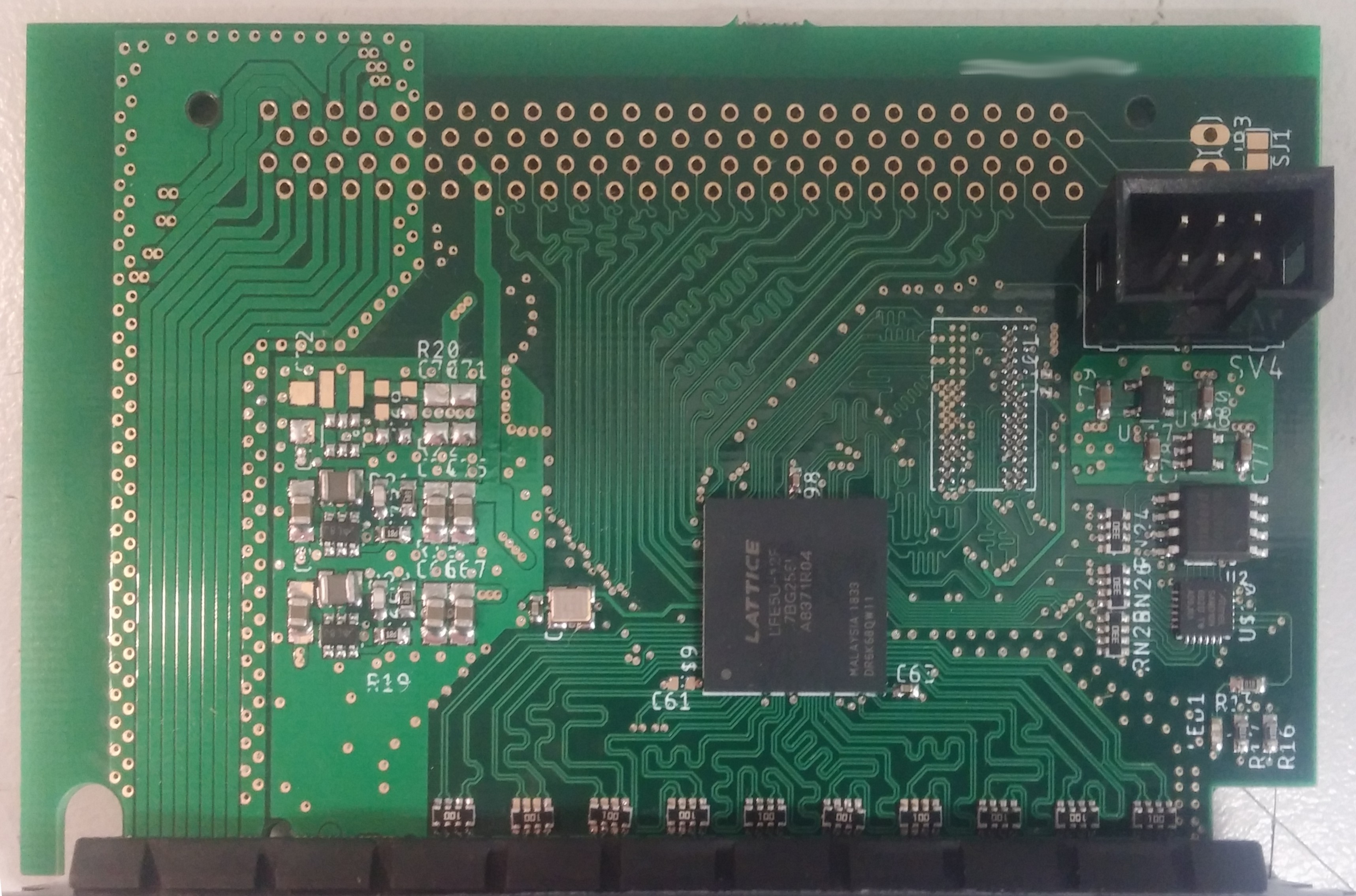


 Kn/vD
Kn/vD
 Arrow Westervelt
 Dominic Emond-Belanger
We have similar setup being used in customer projects, 64 lines in the backplane, one host board with ZYNQ7000, all slave boards having Lattice XO2. Flexible allocation of backplane signals between slave slots, in standard 19 inch rack.