flow
flow-
Bitstream Configuration via MQTT
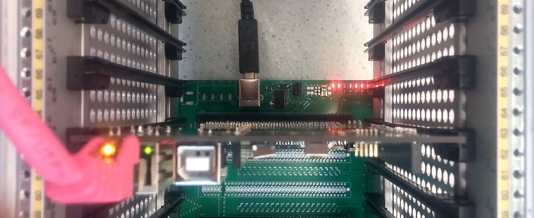
05/14/2019 at 22:21 • 0 commentsI finally managed to upload the FPGA bitstream via MQTT.
![]()
At the moment I use a protocol in which I publish the bitstream split up into messages of 128 byte each into a different topic and let mosquitto (the MQTT Broker) ensure that they all arive. At the moment the bottleneck is the Serial Port between the ARM board and the configuration Controller but in the next days I am going to work on sppeding that up.Now I will start working on the bitstream that will go into the FPGA that configures all the other boards on the bus.
-
Ethernet is Working & a Nice Enclosure
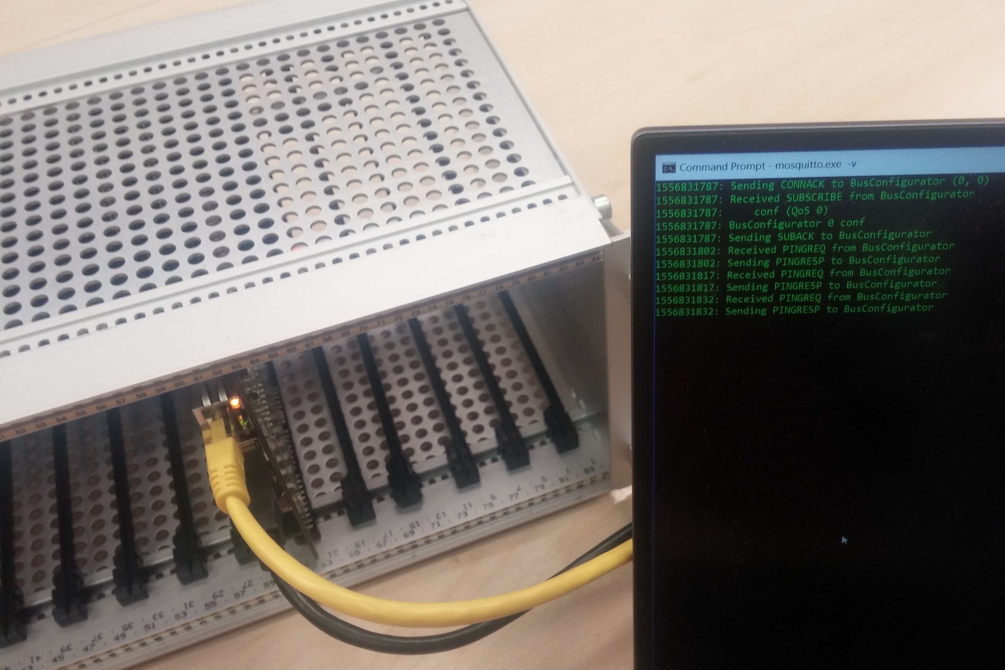
05/02/2019 at 22:32 • 0 comments![]() I finally managed to get the ethernet chip running i suspect that the crystal had a bad contact. From there on I managed with the help of the pubsubclient library to get the thing talking. Also I managed to score a really nice enclosure for the project on ebay.
I finally managed to get the ethernet chip running i suspect that the crystal had a bad contact. From there on I managed with the help of the pubsubclient library to get the thing talking. Also I managed to score a really nice enclosure for the project on ebay.
I decided to use MQTT for the configuration of the system because it is so leightweight, easy to implement, and well established. -
Some trouble with the CPU board
04/30/2019 at 21:30 • 0 commentsThe first problem I had whil working on the CPU board is that I locked out my self. I should have added an erase button. Which was easily made good for with some hot glue.
![]() Now I am struggeling with the W5100 that I want to use for the ethernet communication and the upload of the bitstreams. The Oscillator doesn't start unless I touch the oscilator circuit with my finger. So I presume something is off with the capacitors. If somebody has debugged something like this before I would be happy about some pointers. (So far I never took to much care about Crystal resonators and they always worked out)
Now I am struggeling with the W5100 that I want to use for the ethernet communication and the upload of the bitstreams. The Oscillator doesn't start unless I touch the oscilator circuit with my finger. So I presume something is off with the capacitors. If somebody has debugged something like this before I would be happy about some pointers. (So far I never took to much care about Crystal resonators and they always worked out) -
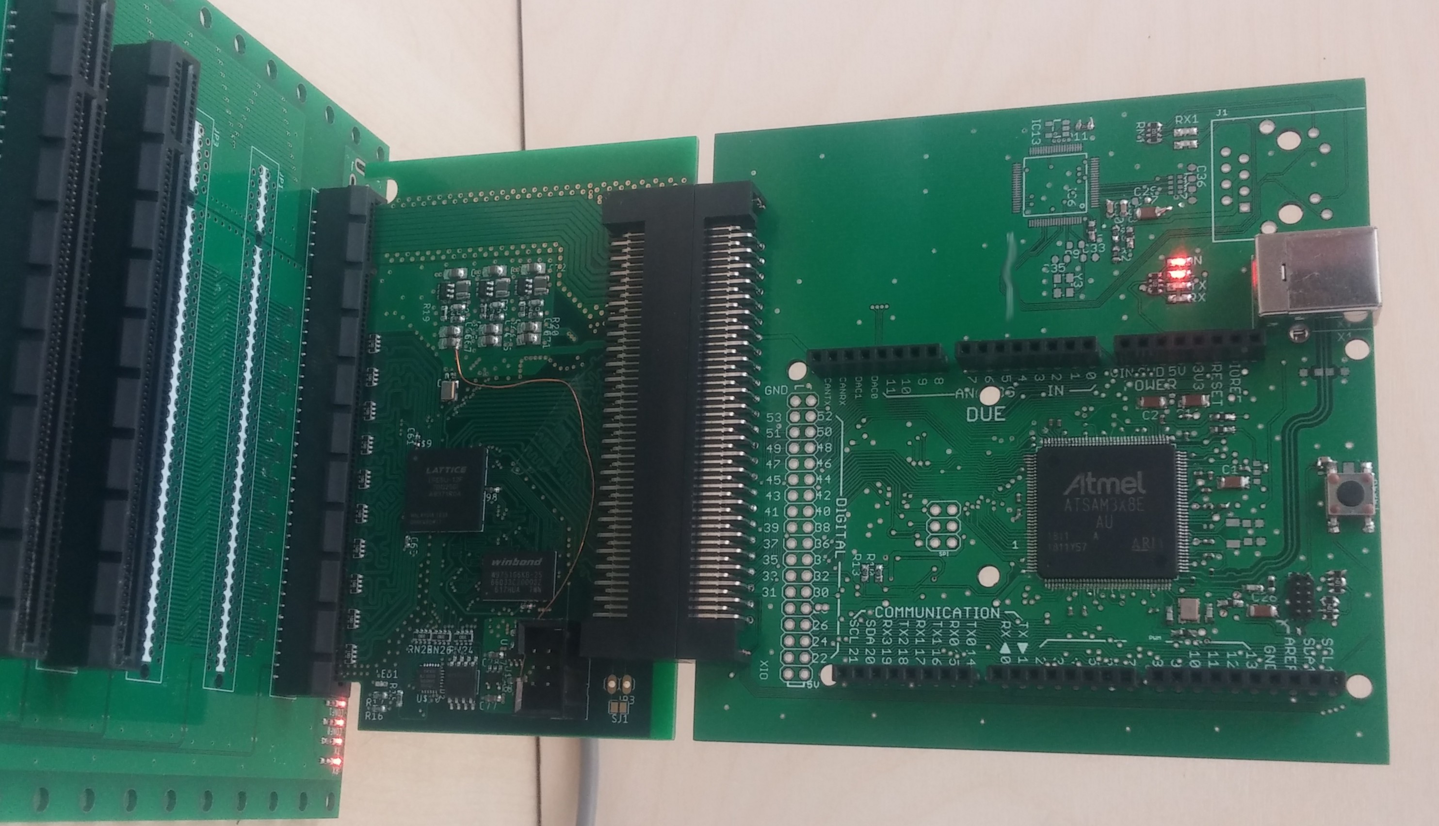
The Shield Board (Arduino-Compatible) works.
04/28/2019 at 14:34 • 0 comments![]()
I just put together the first usefull Board that can go into the FBus. It has a SAM3X8 and Arduino-Compatible footprints for shields, so now you can hook up any shields to the FBus. Now I will start working on the ethernet interface. I hope that it soon will be possible to upload the bitstreams and firmware images via ethernet.
-
It's Alive.
04/26/2019 at 22:04 • 0 commentsA little bit of verilog
module blinky(CLK50, PW39, NW39);
  input CLK50;
  output PW39;
  output NW39;

  reg [24:0] count;
    always @(posedge CLK50) begin
      count <= count + 1;
  end

  assign PW39 = count[24];
  assign NW39 = count[24:13] < count[12:1];
endmodule
The SymbiFlow toolchain and a lot of serial interface debugging and the FPGA finnaly shows some life:
![]()
-
The Backplane PCB Arrived!
04/25/2019 at 23:19 • 0 commentsToday the Backplane PCB arrived. I soldered a few PCIe connectors and let me tell you soldering 4 times 164 pins takes quite some time... But I can communicate with the bootload Microcontroller! So it worked :-)
![]()
-
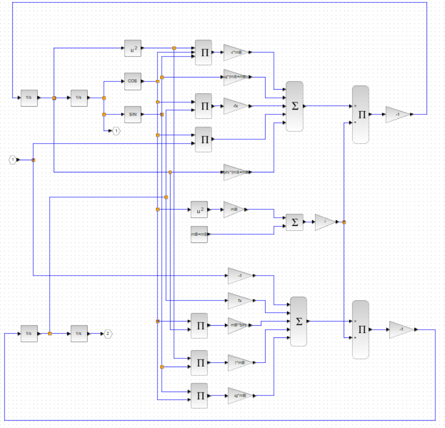
The Inverted Pendulum: Some Control Engeneering
04/21/2019 at 14:16 • 0 commentsAt the moment I am home for Easter so I cant work on the physical parts of the project. Nevertheless, I used a little spare time to think about the control system for the inverted pendulum. I started off by constructing the equations of motion for the pendulum using Mathematica and transfering them to XCos my first atempt while somewhat asthetically pleasing took far to long to implement:
![]()
Also I wanted to keep the process more open so I opted out of Mathematica and instead wrote a small Python script that uses the sympy library to construct the equations of motion using Lagrangian mechanics and generates the code to be directly dumped into a XCos Scilab function block. And TADDA it swings:
![]()
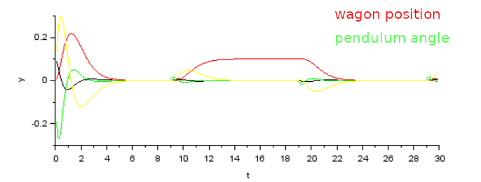
Then I refreshed my controll theorey memories with this awesome tutorial: https://www.youtube.com/watch?v=M_jchYsTZvM and implemented linearization and poleplacement for the controll loop in the same Python script: https://cdn.hackaday.io/files/1647527048749568/inverted_pendulum_controll.pyWith that in place I was able to run the first simulation of the inverted pendulum in the upright position:
![]()
In the beginning the pendulum recovers from beeing in a slightly of vertical angle. Afterwards it performs a controlled movement of the Wagon on which it is mounted forward and backwards.![]()
I am really looking forward to implement this in real life! :-) -
Second Board Soldered & a Manual Stencil Holder
04/17/2019 at 18:20 • 0 commentsUnfortunately I forgot to select the option to get the solder stencil cut to size. So It was quite uncomfortable to work with. And on the first Board it often slightly warped away from the Board an caused solder paste leaking around the pads. I tried my best to hold the stencil down with my hands but one corner would always eventually lift. To combat that I laser cut a small U-shape from Plywood to have a more easy way to hold the stencil down. With that I experienced no more leaking solder pads.
![]()
Probably I was just reinventing the wheel. Nevertheless, with this thing I managed to solder the second board and it turned out perfect except for two little tombstoned 0402. And there it is:
![]()
-
A Target: an Inverted Pendulum
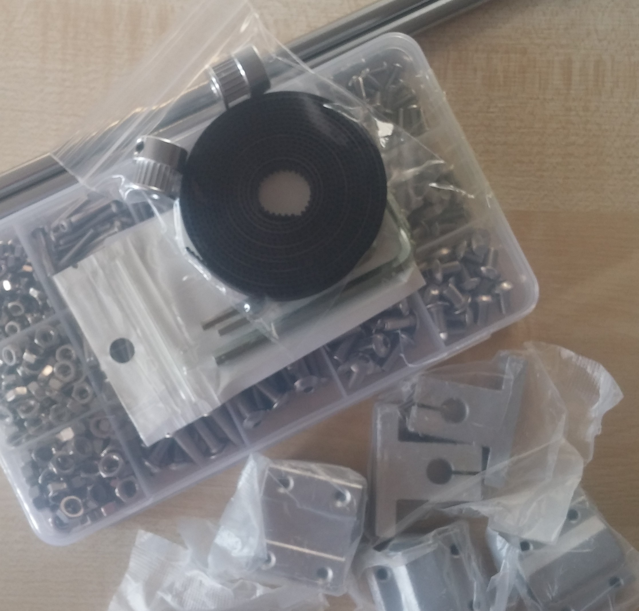
04/15/2019 at 20:12 • 0 comments![]()
Working on electronics only gets a little bit dry so I decided to make a small example project using the actual FBus system. I settled for the most popular example to apply control theory: the inverted pendulum. The first parts for it already arrived :-).
-
First Board soldered
04/08/2019 at 22:34 • 0 comments![]()
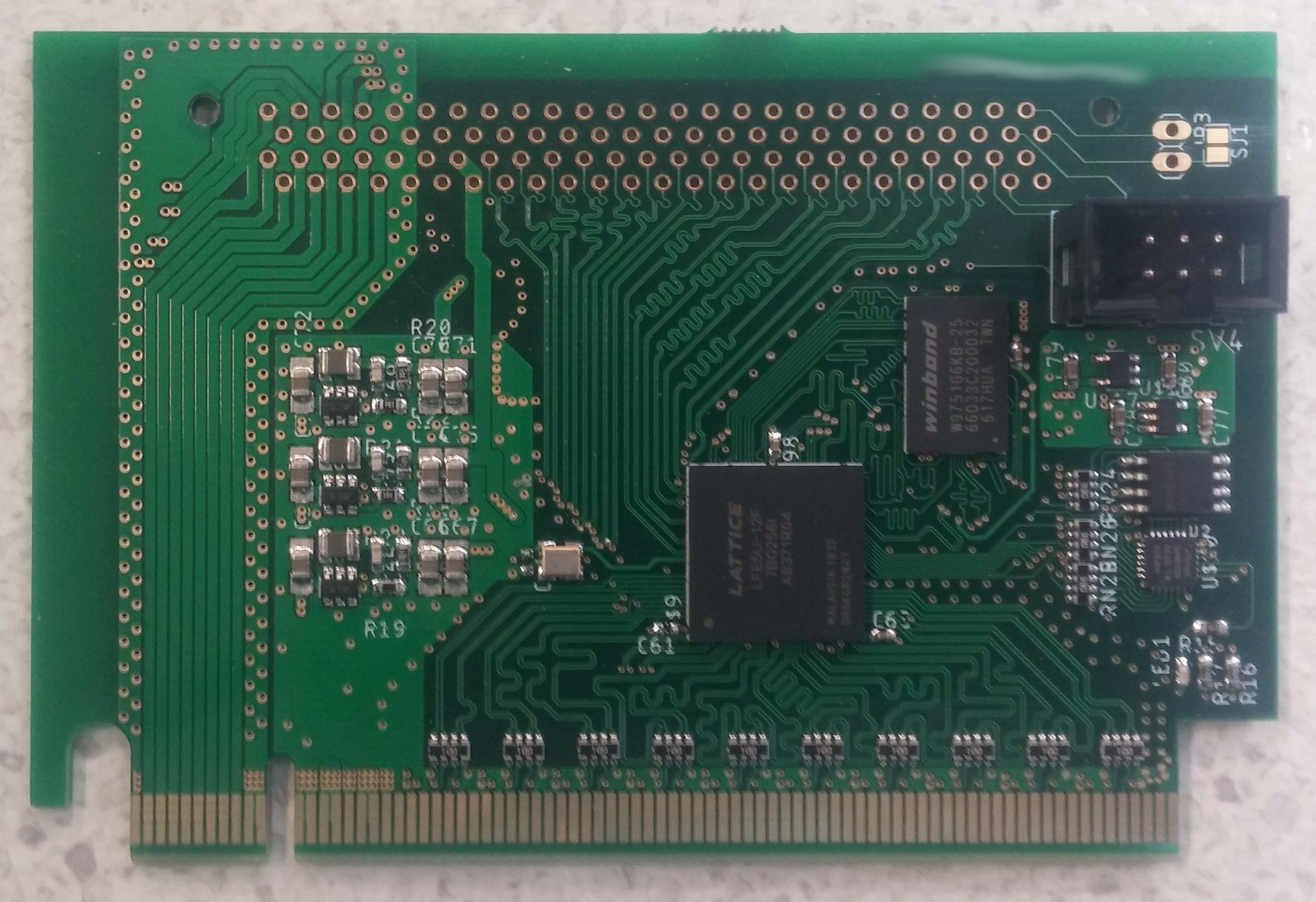
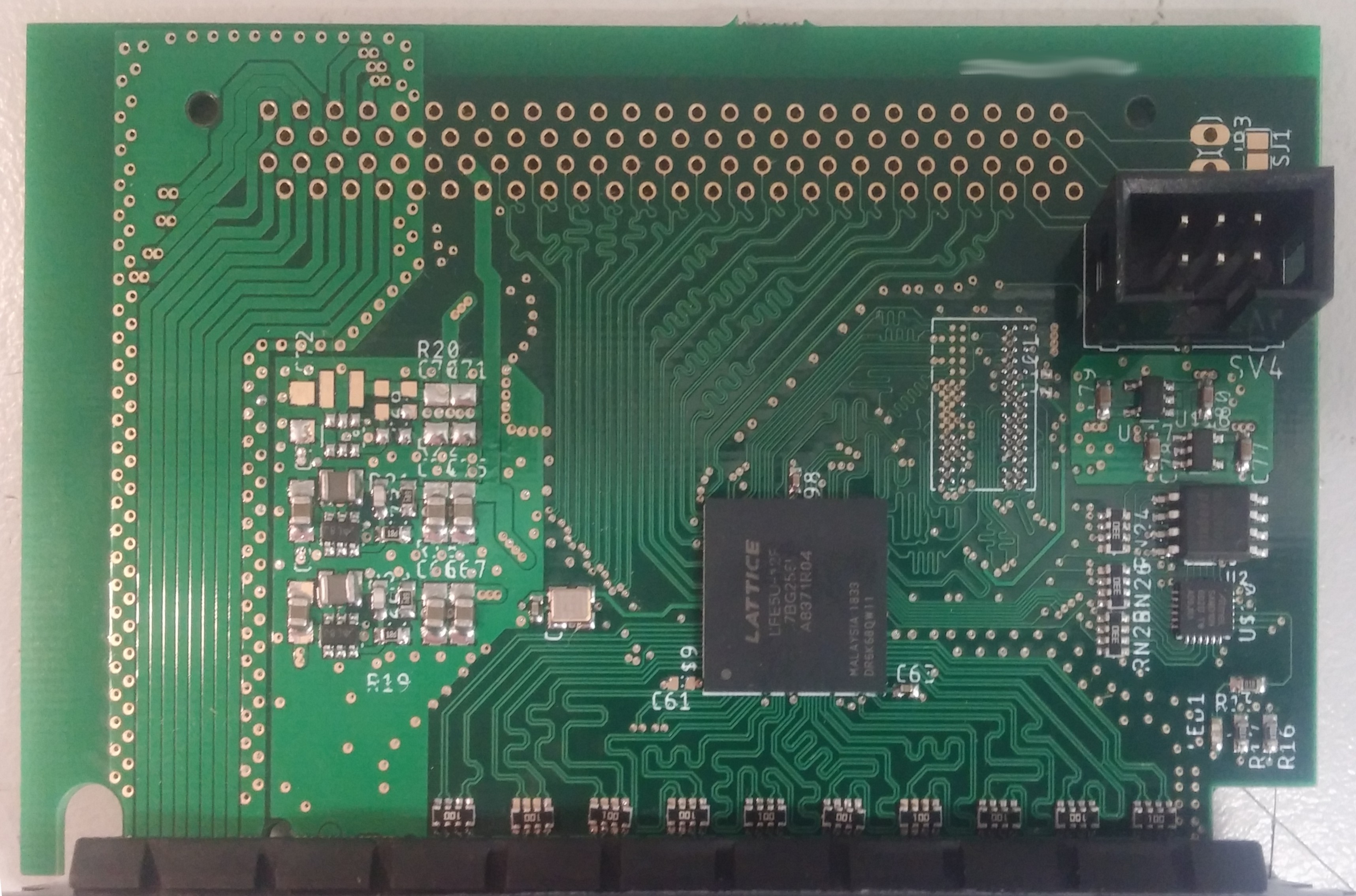
The first Board is soldered :-). On this board I did not populate the DDR2 memory or the associated power supply to reduce the total points of possible failure.
As a first test I flashed a bootloader on the SAMD10 and it worked :-). In the next days I will implement bitstream loading for the Lattice ECP5.
FBus: Open FPGA Realtime Bus
Defining and implementing a bus protocol that is built around low-cost FPGAs to enable modular and affordable control and DAQ systems.
 I finally managed to get the ethernet chip running i suspect that the crystal had a bad contact. From there on I managed with the help of the pubsubclient library to get the thing talking. Also I managed to score a really nice enclosure for the project on ebay.
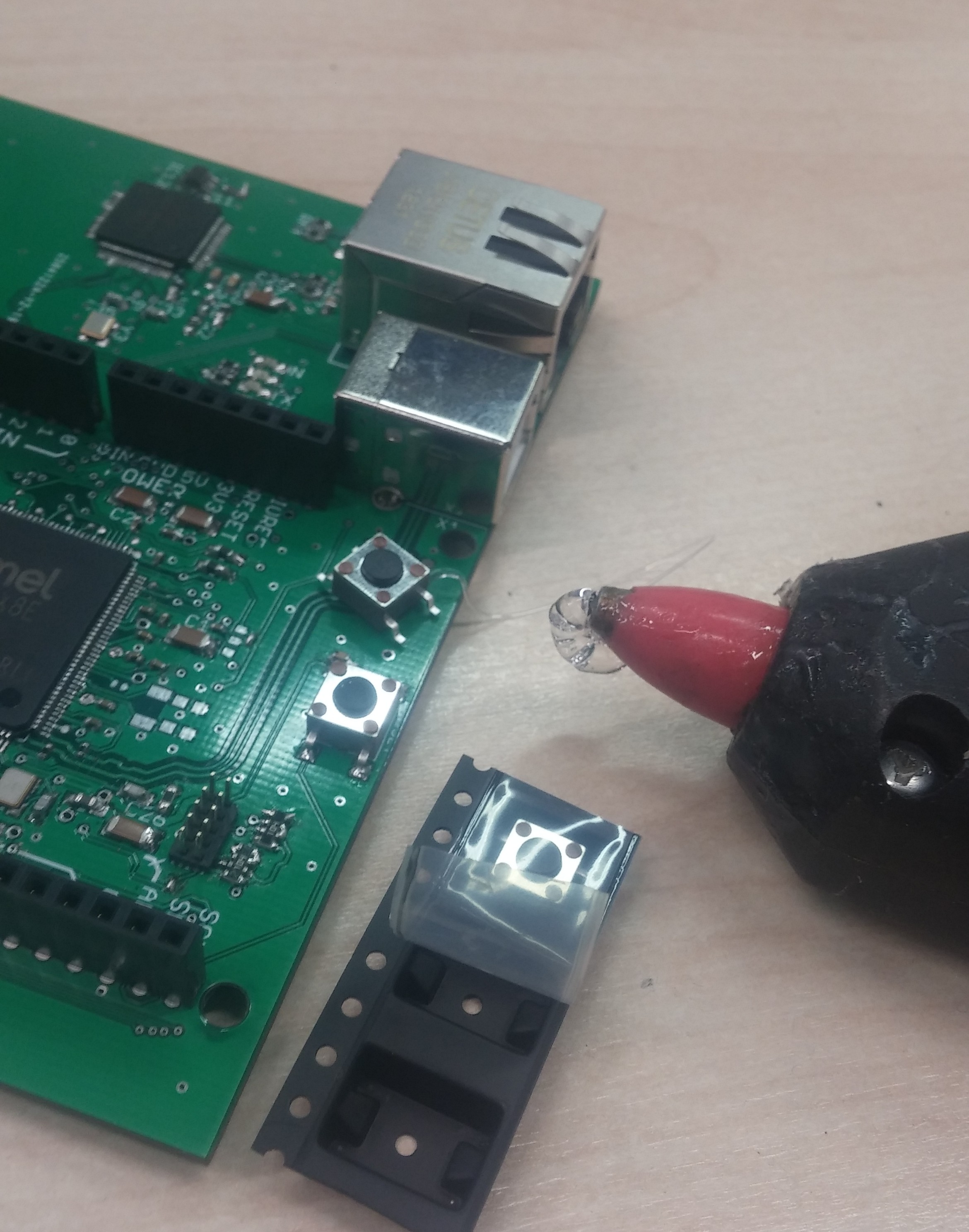 Now I am struggeling with the W5100 that I want to use for the ethernet communication and the upload of the bitstreams. The Oscillator doesn't start unless I touch the oscilator circuit with my finger. So I presume something is off with the capacitors. If somebody has debugged something like this before I would be happy about some pointers. (So far I never took to much care about Crystal resonators and they always worked out)