I programmed a first version of my own Tensorflow 'Fiddler'.
For now it uses provided datasets. The goal was to get familiar with parameters, scalers, optimizers and training procedures.
This is the first app that i programmed ever. In a language that i have never written in before (python).
As can be seen in the next pic, i am running into my own knowledge cutoff when the dataset has different numbers of output Neurons or a way to display the result correctly. The app does adjust automatically for Input neurons and one extra hidden Neuron Layer can be activated. As well as all things that can be adjusted are 'broken out'. Still, more fiddling + research needed here.
It gets real weird with the 'digits' dataset obviously since my Fiddler is not set up to handle this kind of output. Or does it? The output displays a '1'.
Also a way to properly test a trained model is missing. Right now the model tests itself with one datapoint after it has finished training on top of the automatic eval.
The point of all this is to make a hub that can be used to train my own models with gathered Air Quality Data from the [HEX]POD and then pass on the model to the [HEX]POD for testing detection accuracy.
Do i move on from the existing datasets and start making this app about my own datasets or do i make it handle all the eventualities? To learn more about how all this works the latter would make sense, then build a completely new version of the app optimized for my own use case.
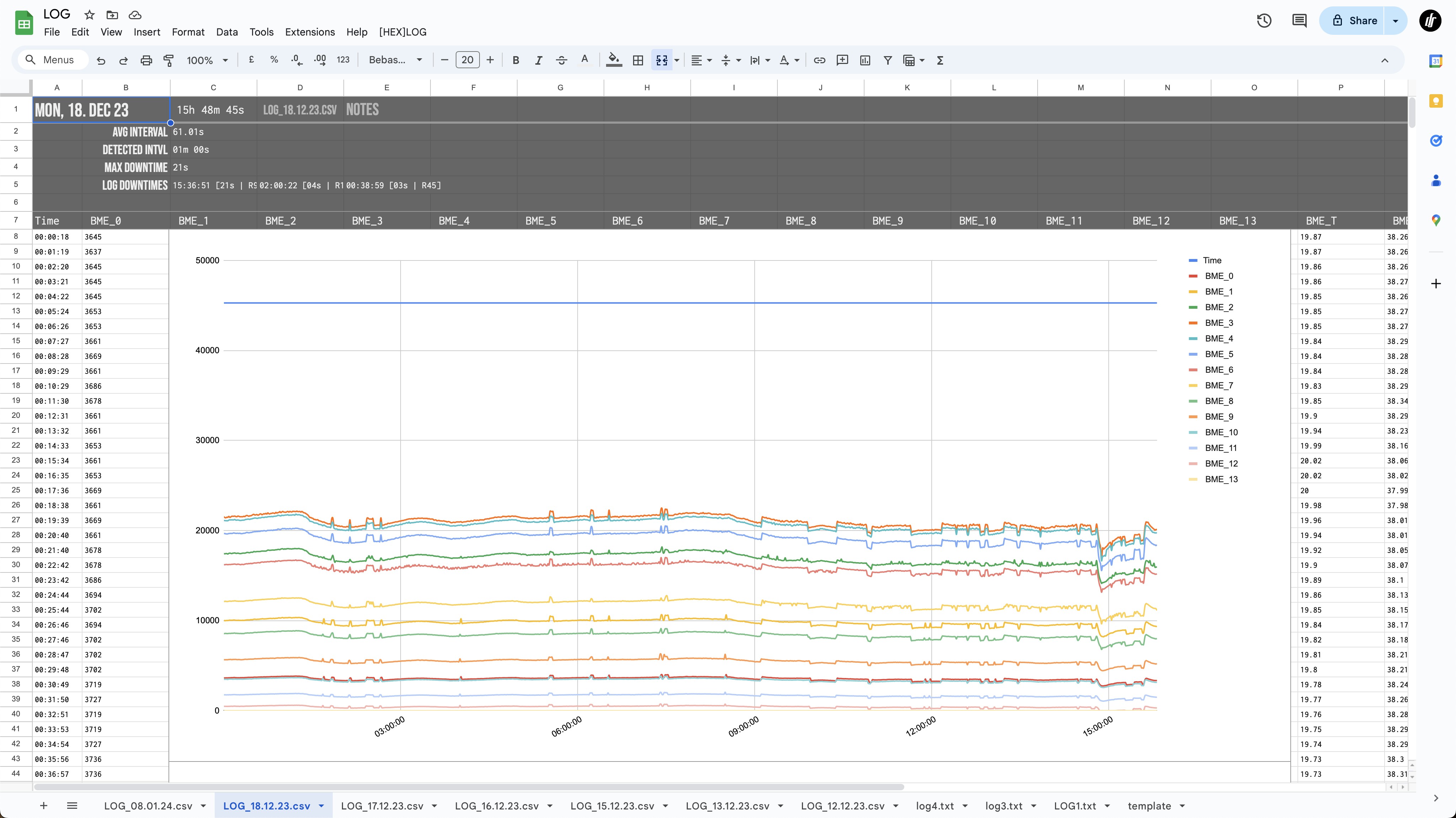
Collecting Sensor Data - Auto-Logs on Google Sheets:
I also programmed an automatic system that imports data logs from the [HEX]POD, detects the interval, and any downtime or missed samples and more. It is automatic for now. I could also embed this meta data into the log, but this seems more robust since it adjusts itself for any eventualities and automatically detects errors during sampling.
To burn in the sensors and get a first idea about collected data, i have run multiple test sessions of 3h - 21h duration. SGP41 and SCD41 - CO2, VOCs, NOx, and multiple redundant Humidity, Temp, Pressure datapoints are also part of the Log.
An option to add Notes during the sampling process, to mark location or environmental changes can be set via the Web Interface only for now.
An overhaul of the OS and Interface running on the [HEX]POD is in order. I also want to assemble another updated hardware version that utilizes both BME688 sensors plus MPU and Ambient Light data.
BME688 profiles:
For now i am only running one incrementally stepping heater / Timing profile on one out of two BME688s. This does not yield any meaningful 'smell' data. A more complex sequence of profiles needs to be implemented. This can be found in the BoschAI app, they provide some good documentation. These profiles need to be chosen carefully, as different sequences of length and temperature respond to different compounds / 'smells'.
Sampling environment:
Another thought i had: I need to build a clean test-environment (maybe a ventilated box with carbon and hepa filters) to reset the Air sensors and provide a baseline for any smells. This would also help with training datasets on only one specific smell, without interference from the environment.
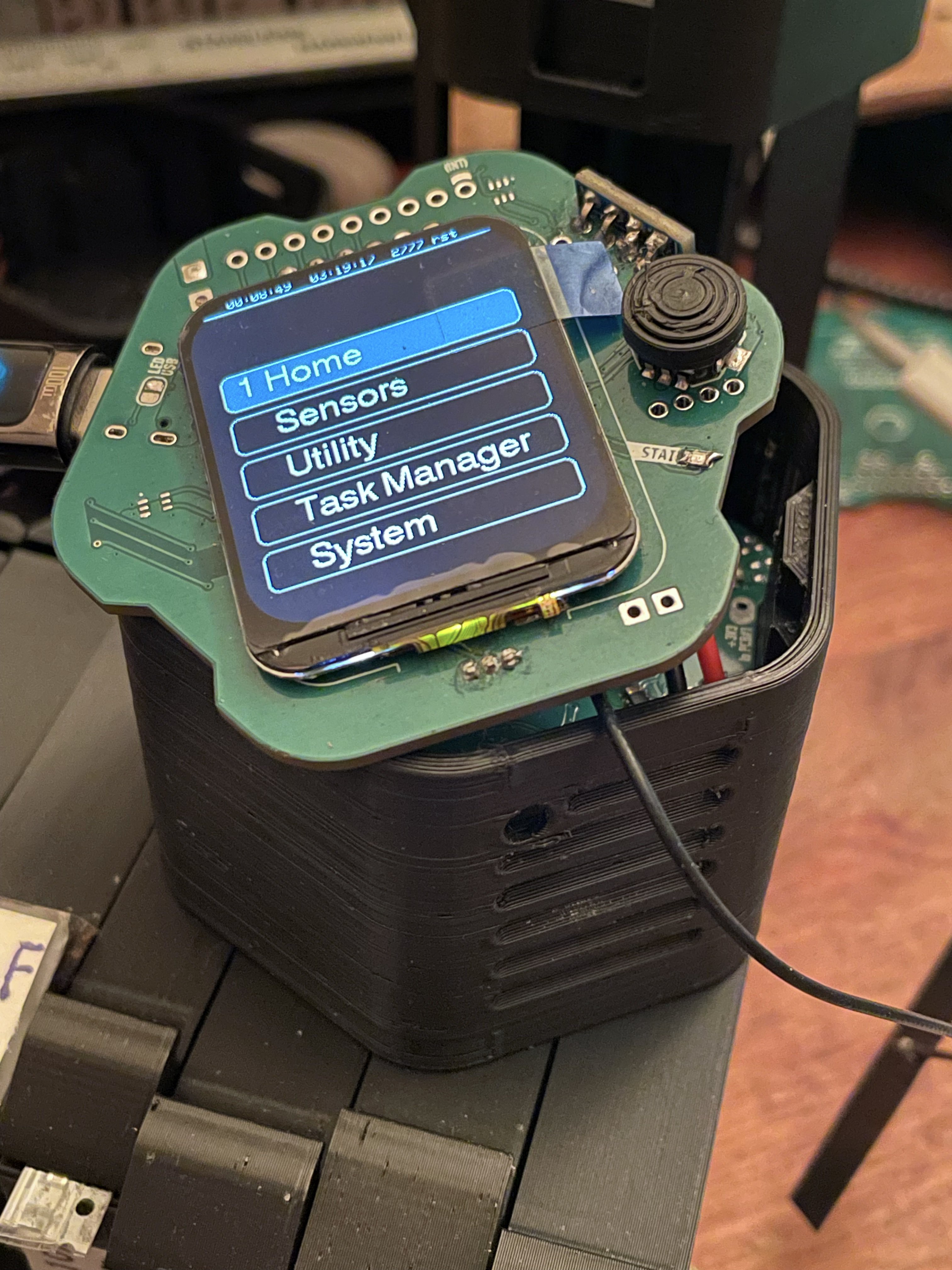
Finally! after a long pause due to job things i am back at the [HEX]POD!
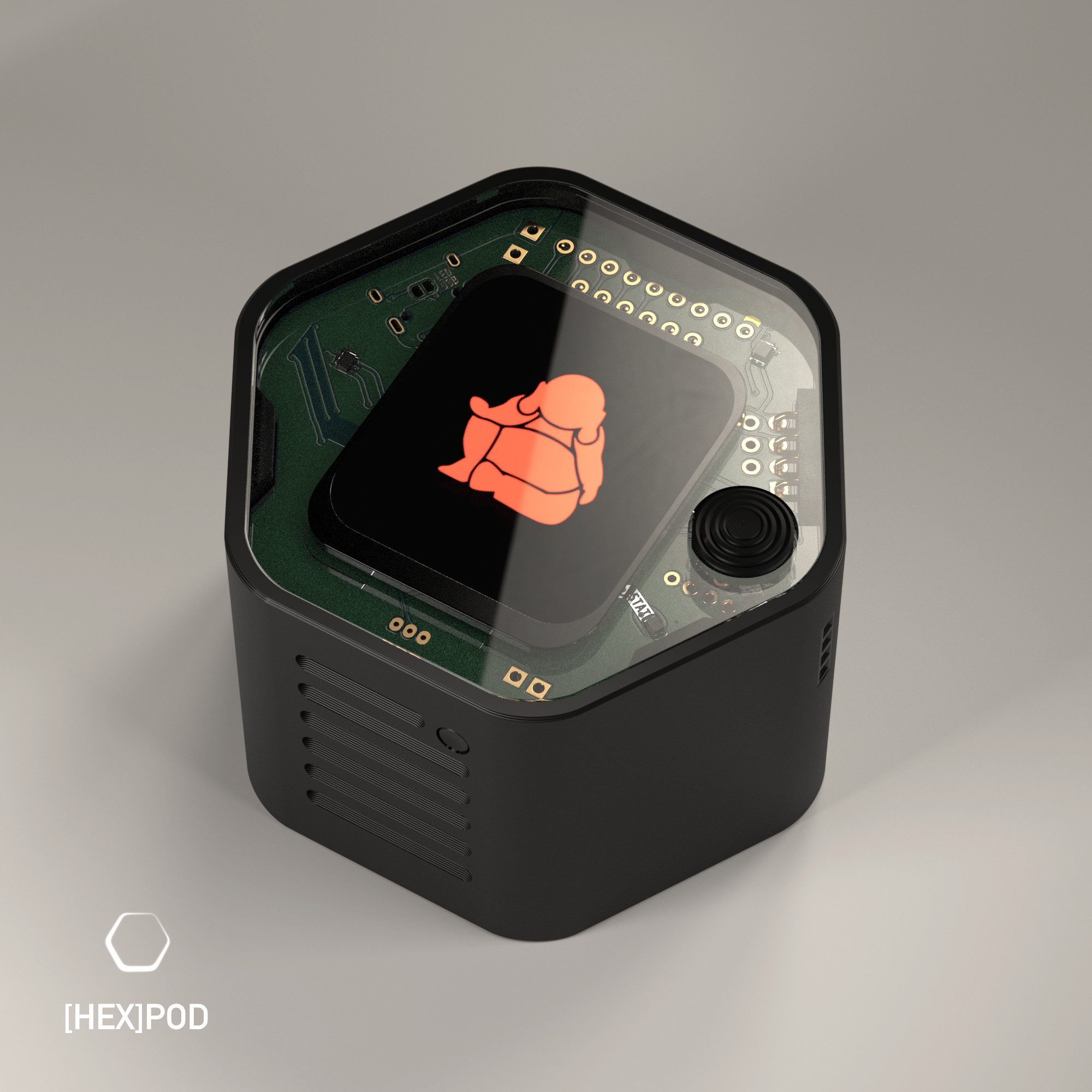
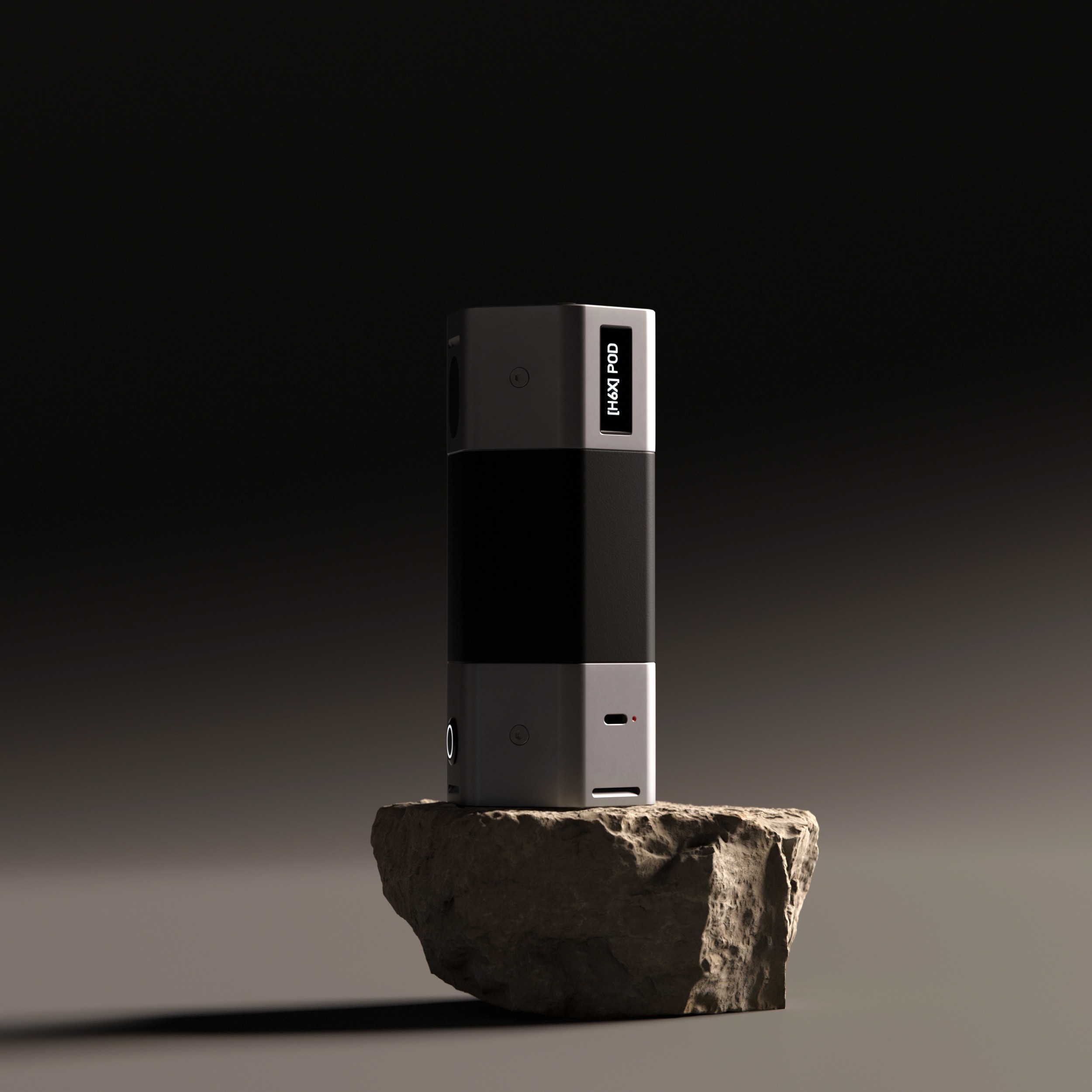
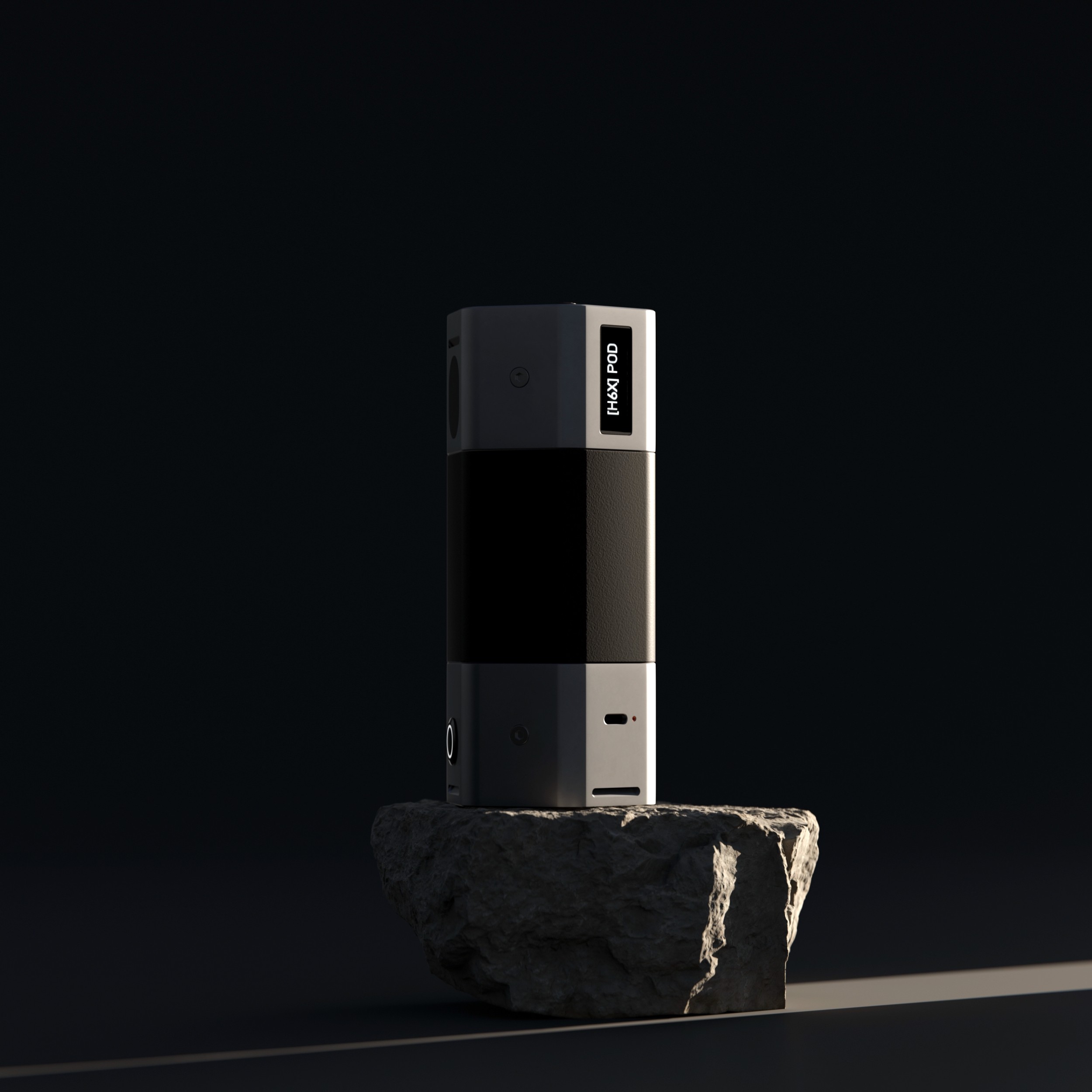
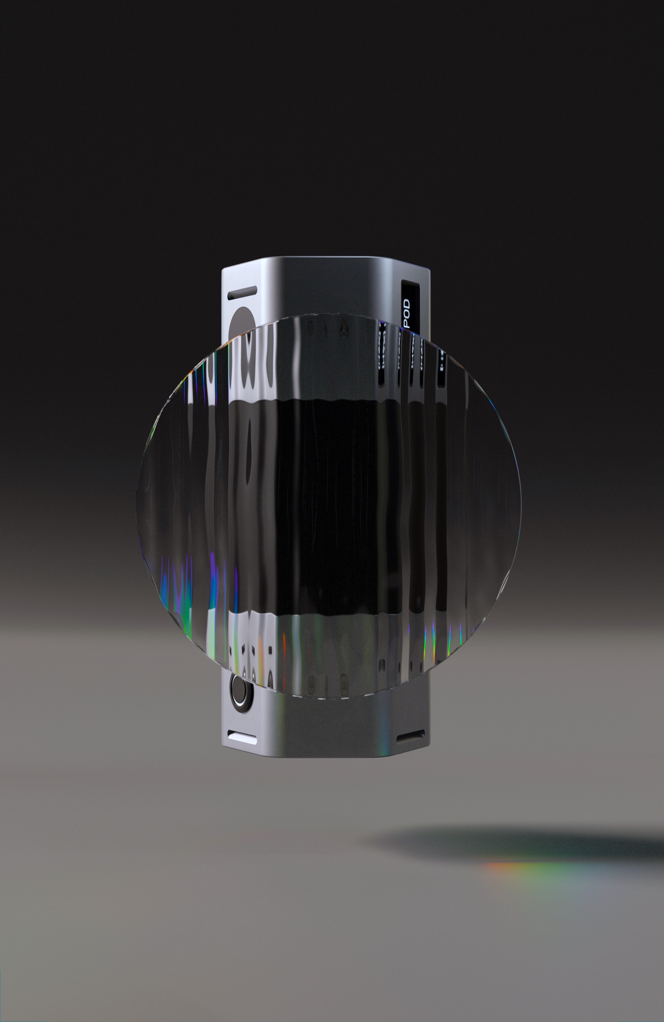
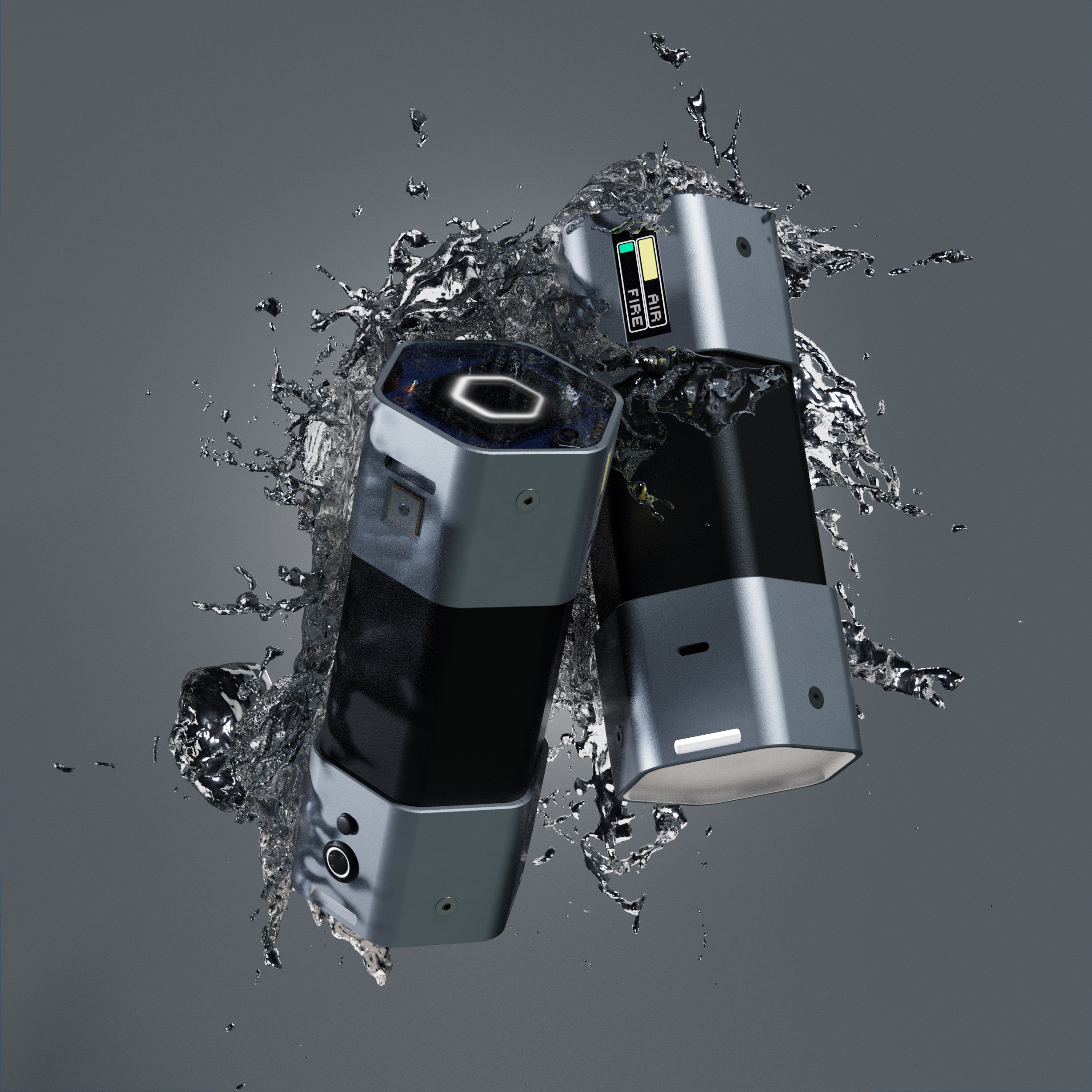
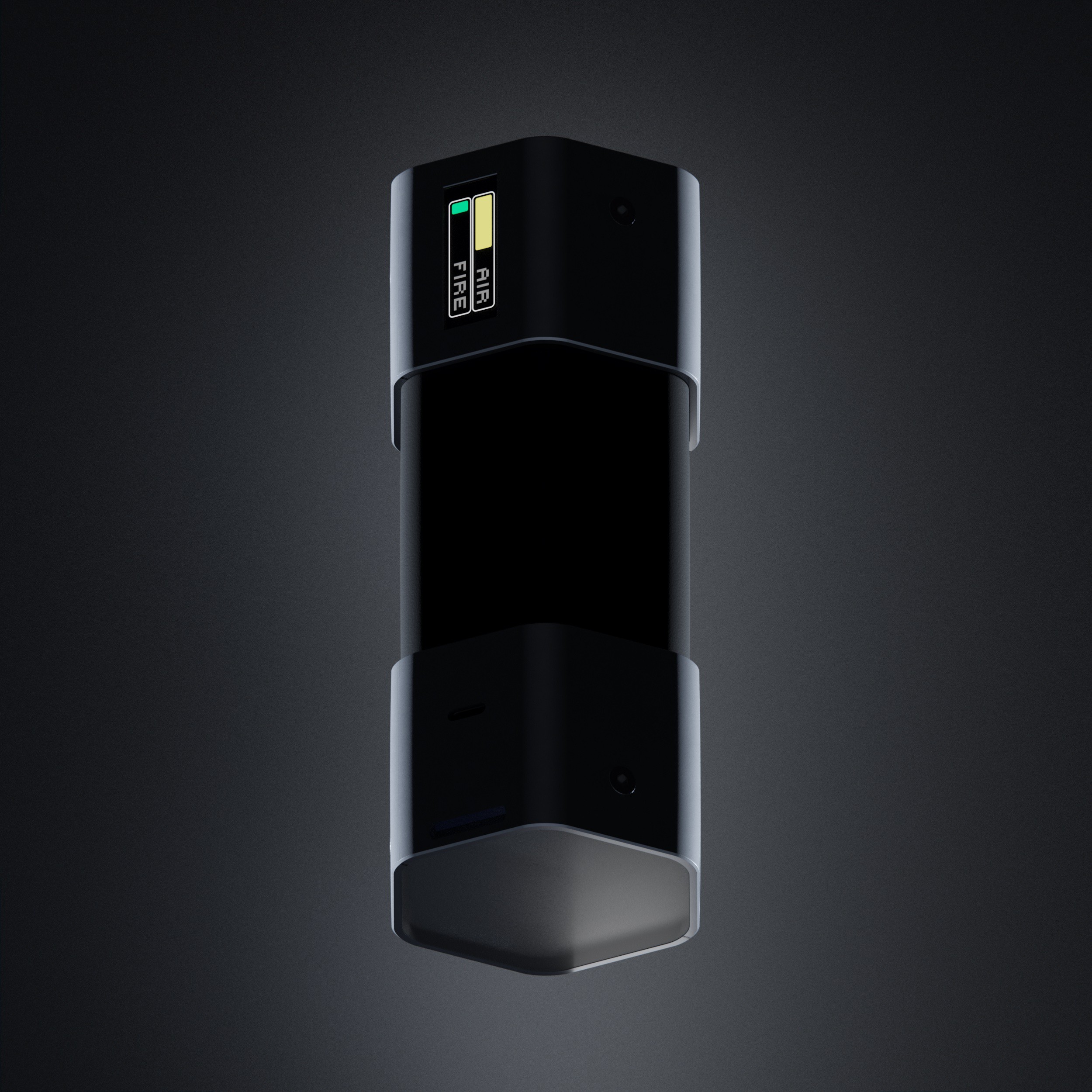
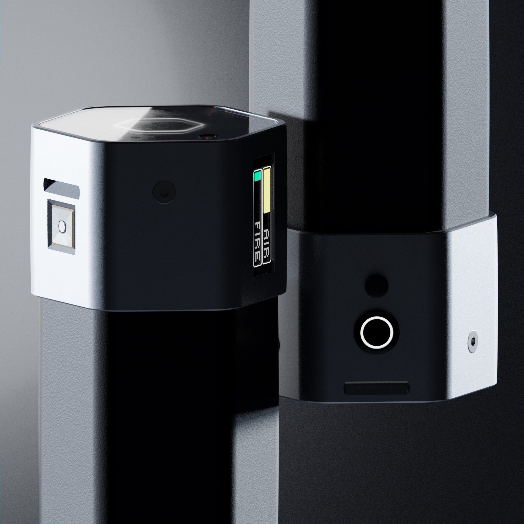
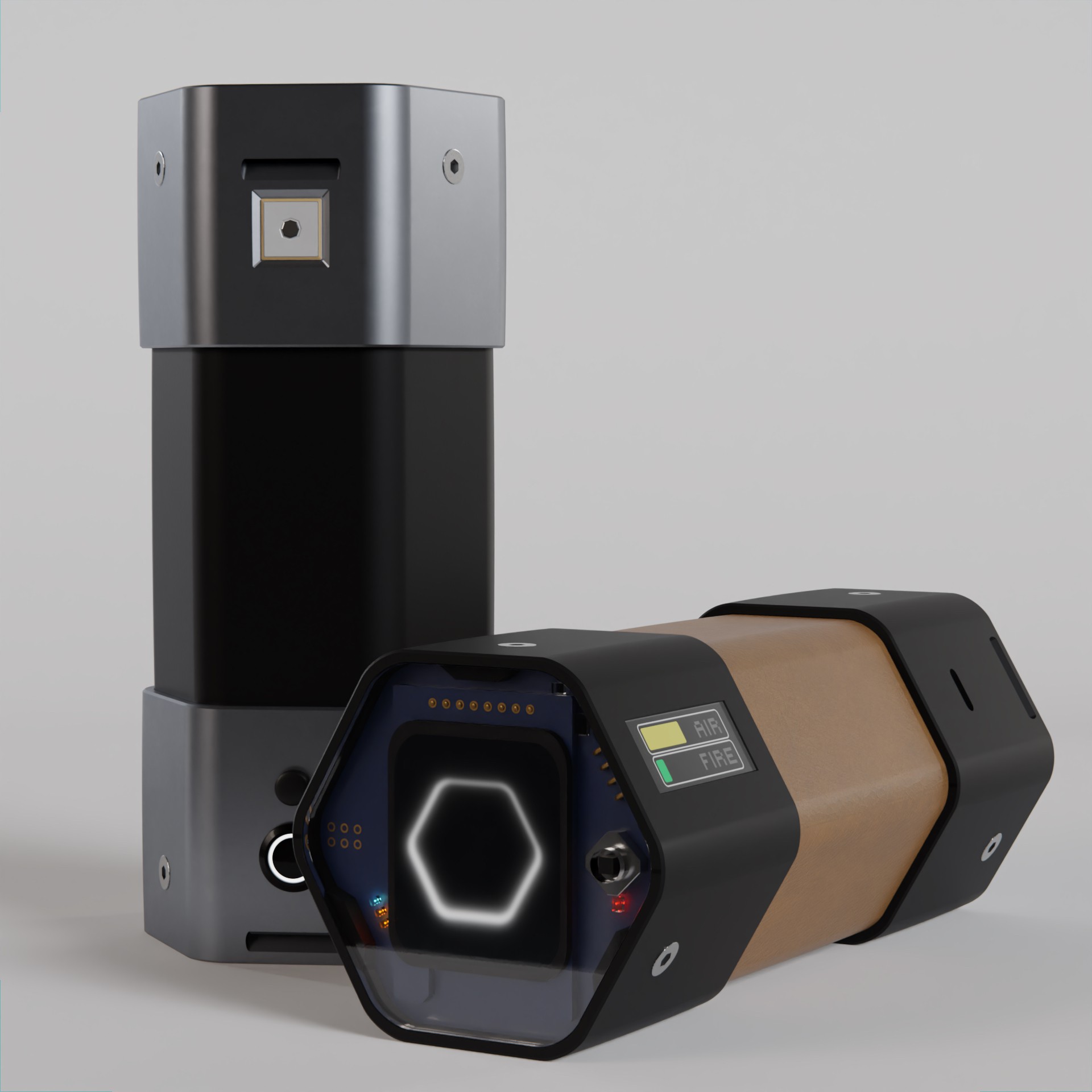
Biggest update is the temporary change to a reduced form factor, a MVP (minimum viable product). I chopped off the lower 2/3rds and fit everything into the top portion of the earlier designs.
Other updates:
new PCB#1 fully working (small bugs)
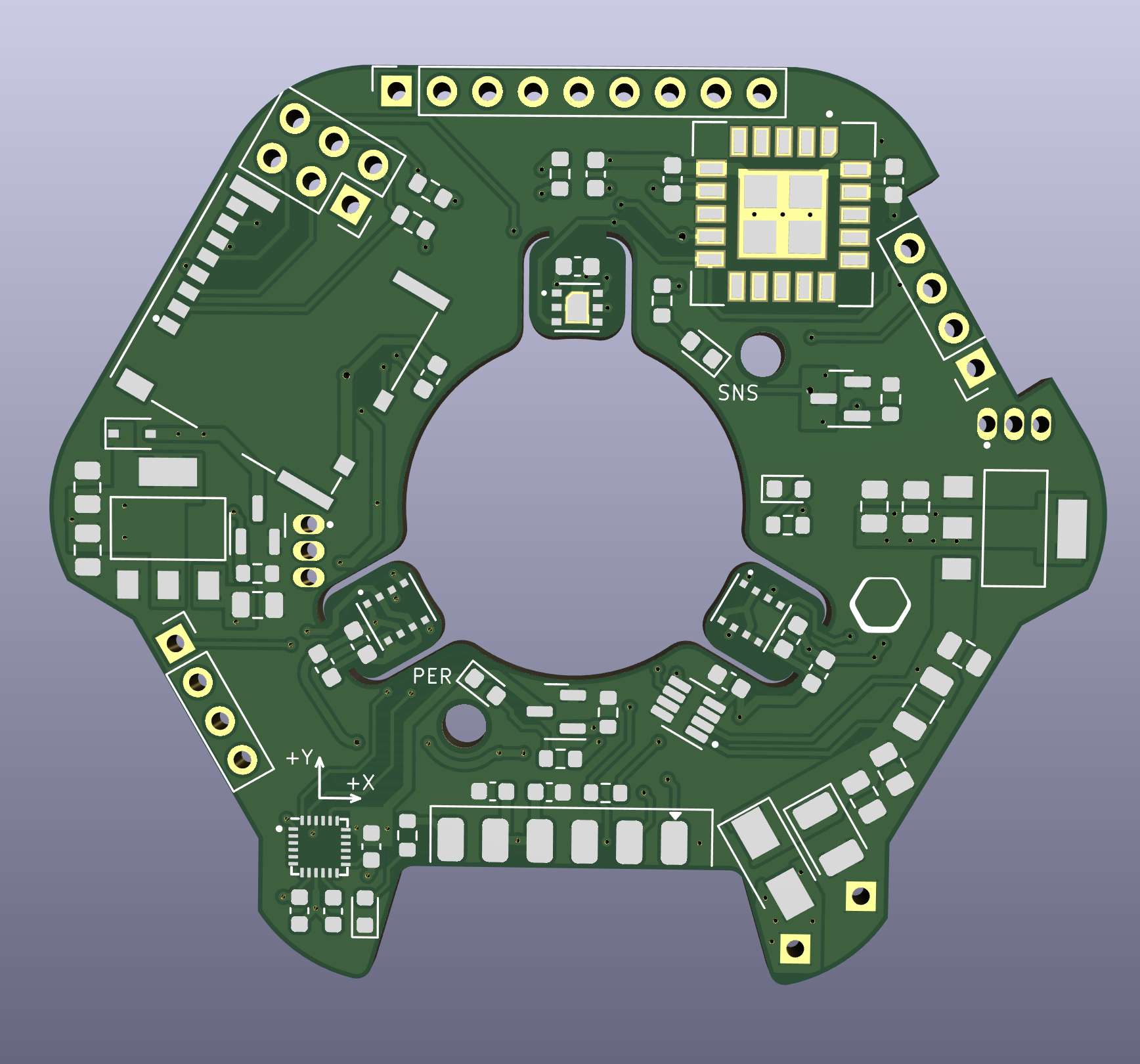
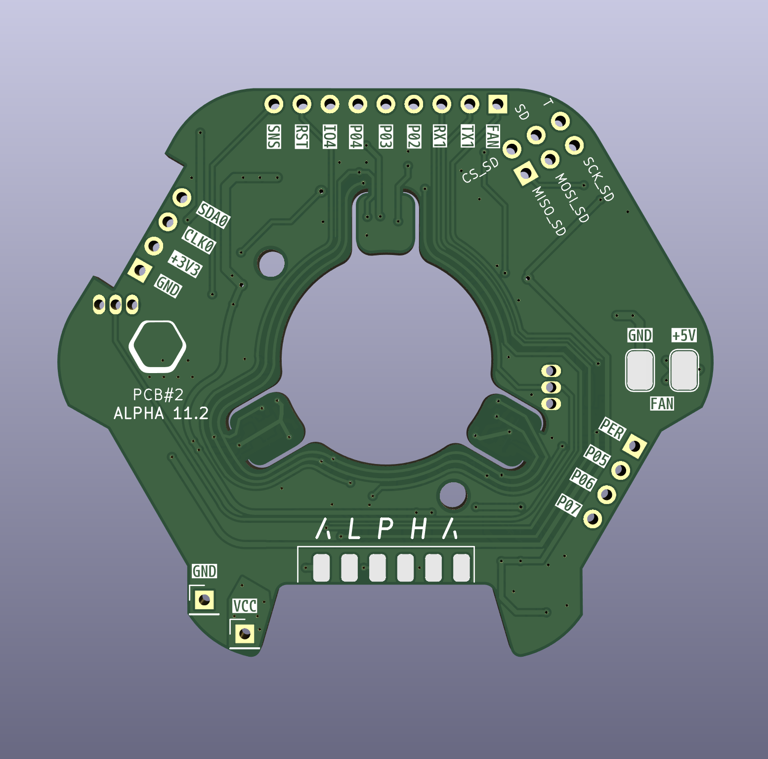
first PCB#2 almost fully working
core functions up and running
Dev interface programmed
Web interface programmed
I made some great progress which i will share over the next weeks.
Here is a sneak peek at whats coming:
- I overhauled PCB#1 another couple of times and am about to order it now. - Updated components for longer lifespan, availability and overall structuring. - Optimized for low current draw in low power mode. - worked a lot on production structure and planning, part organizing, data structuring, brainstorming and
something exciting coming soon!
---------- more ----------
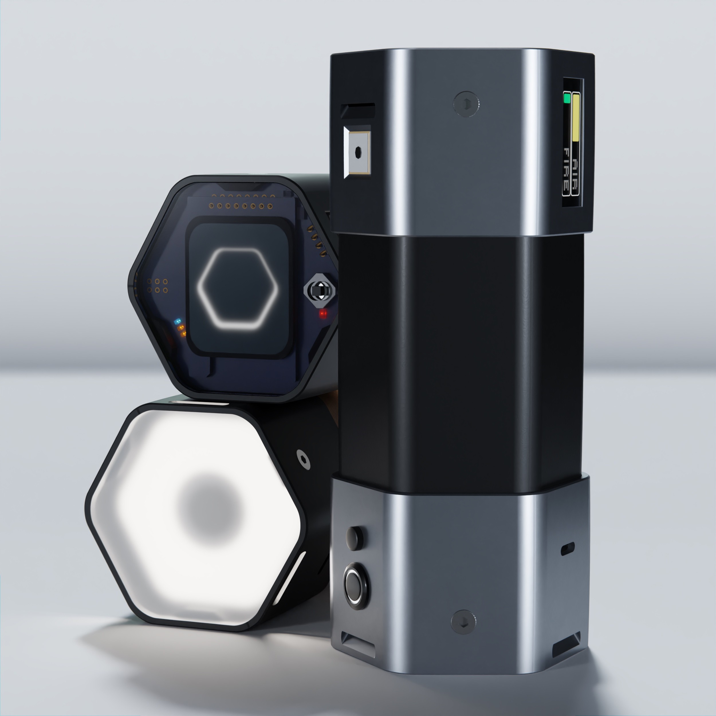
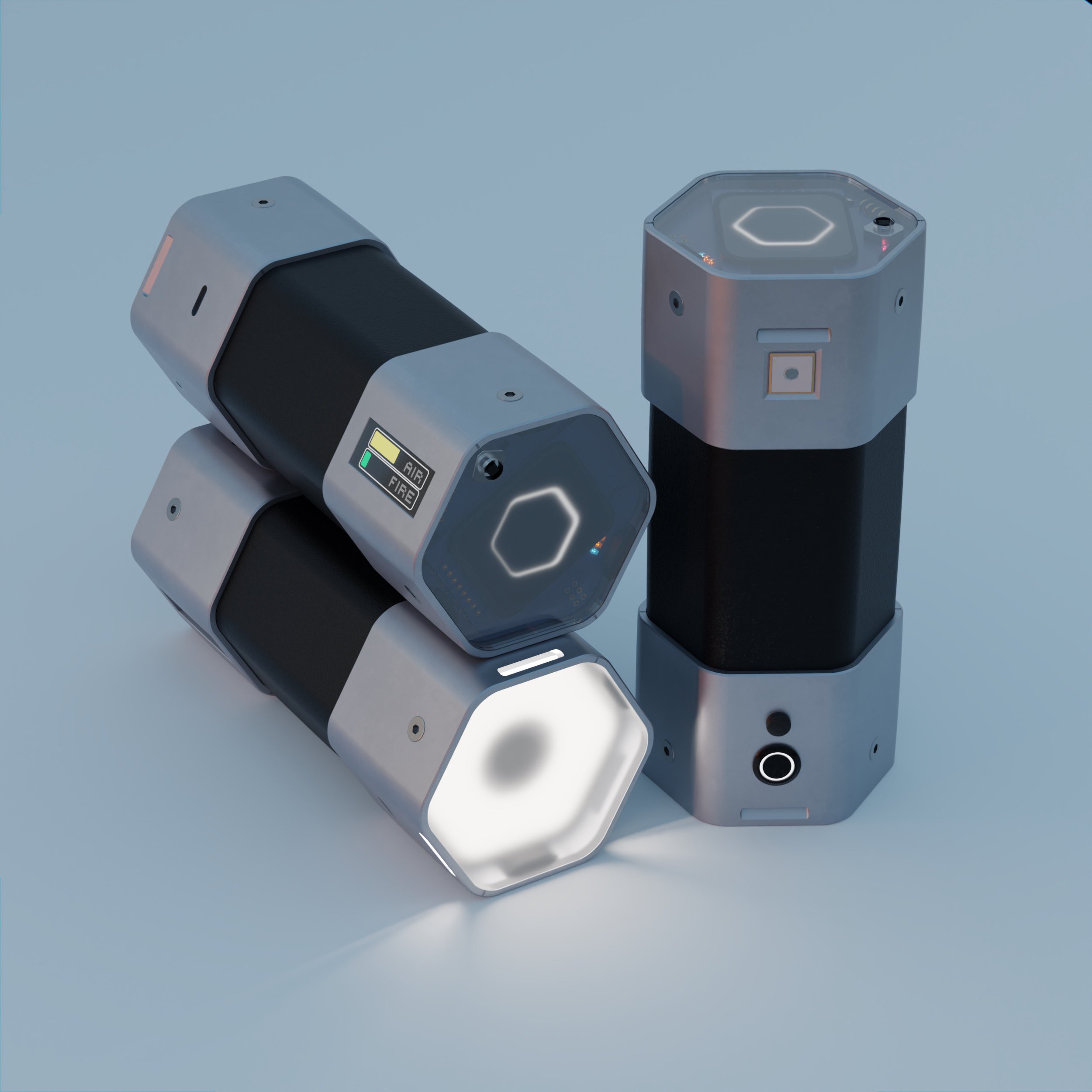
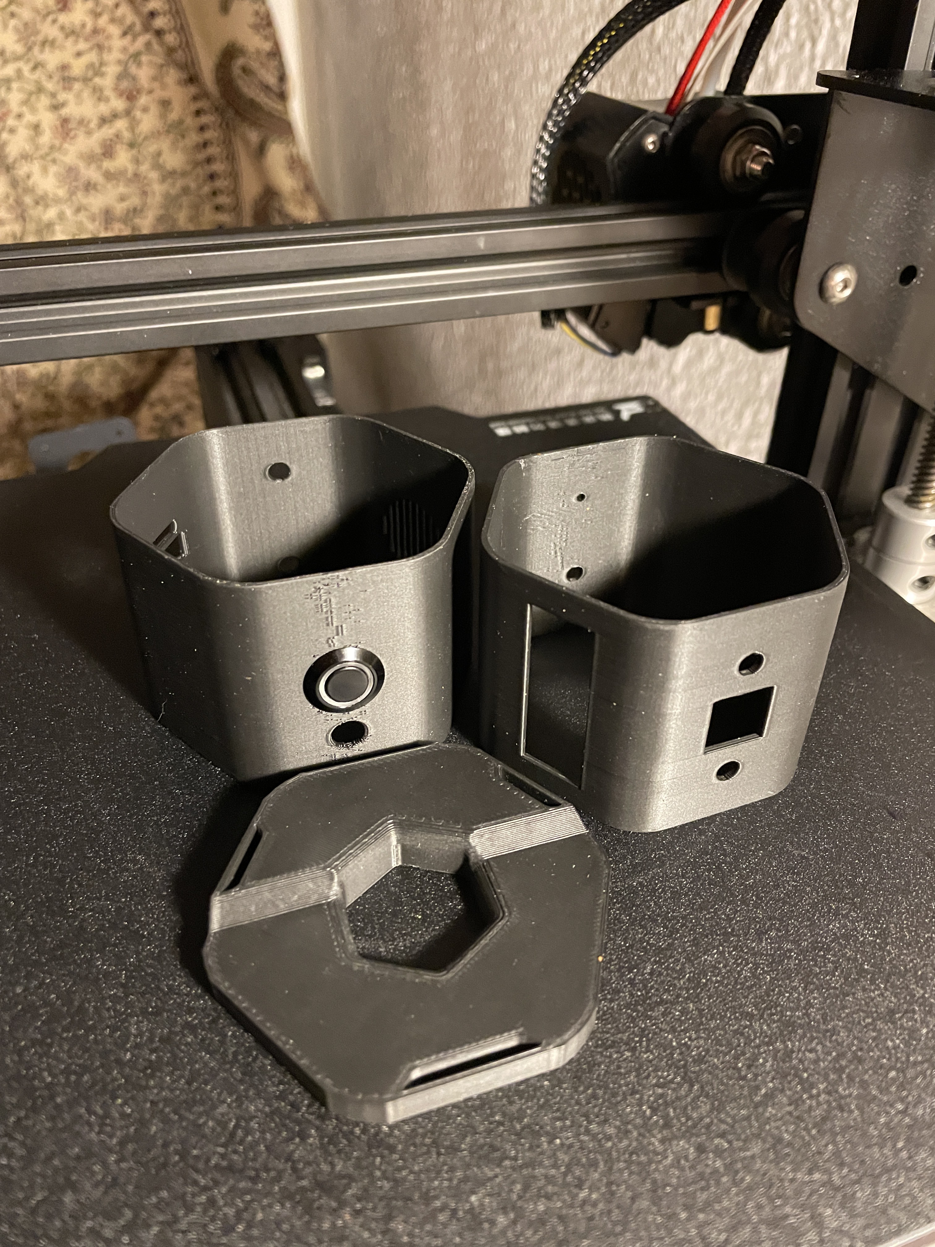
Enclosure design can move forward as well now since the battery contact pcbs are done:
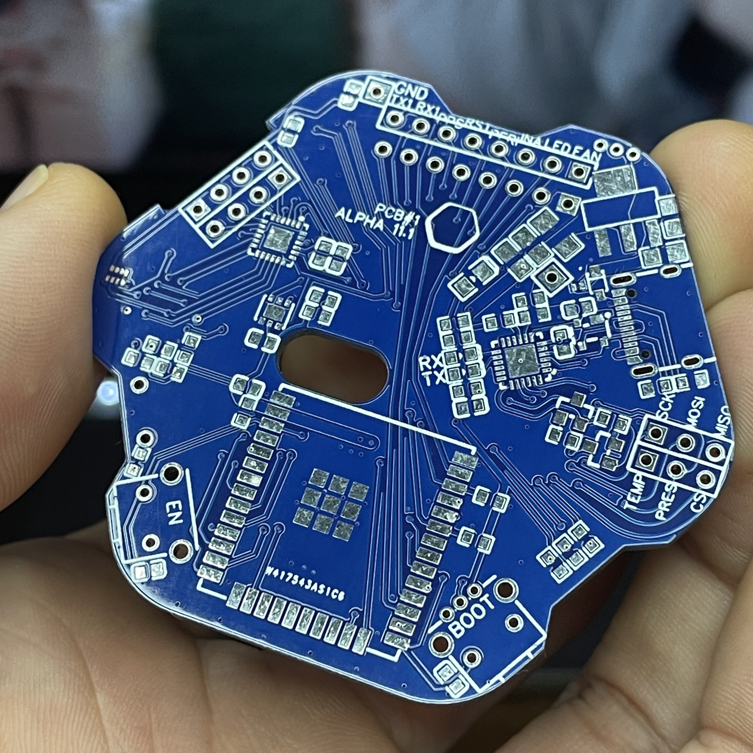
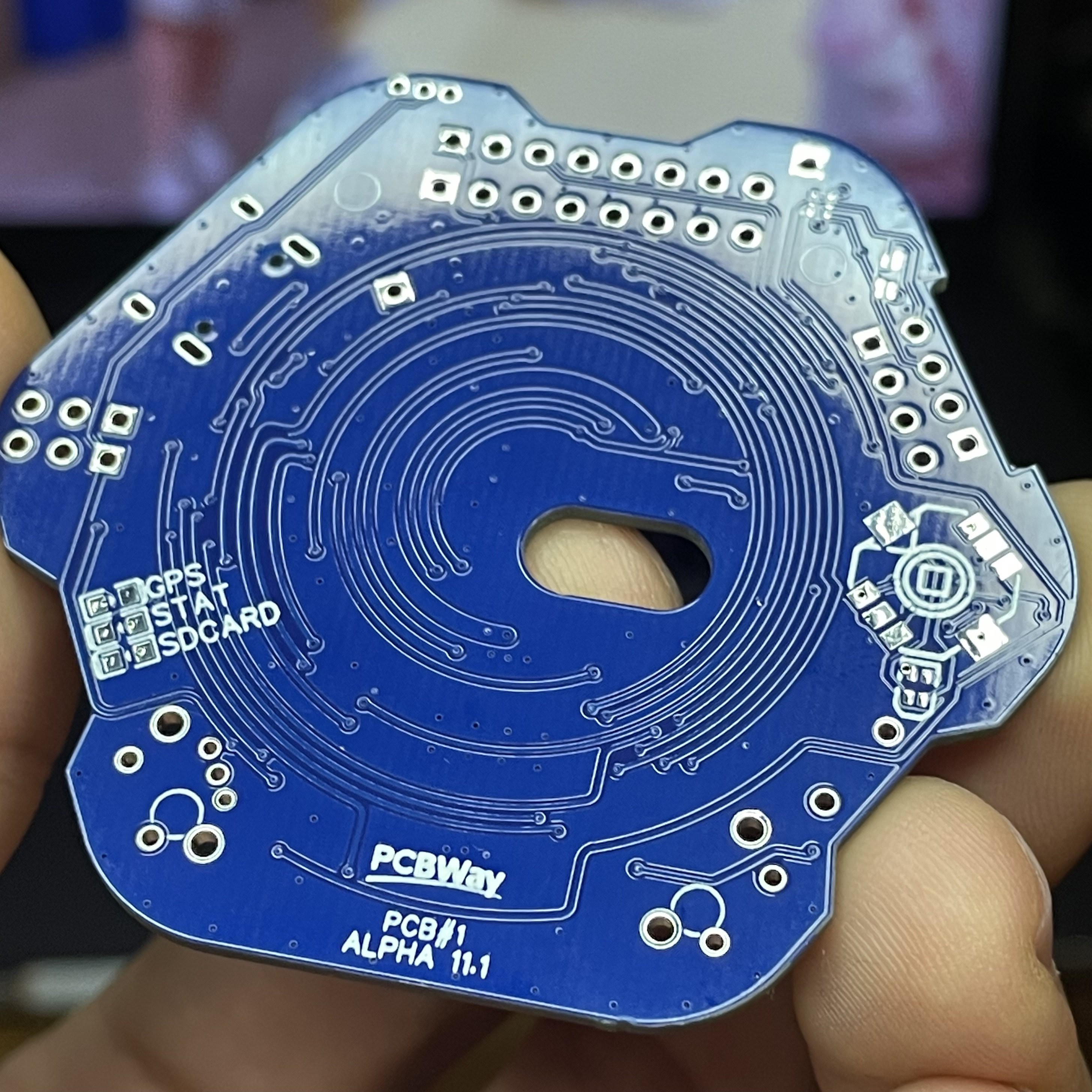
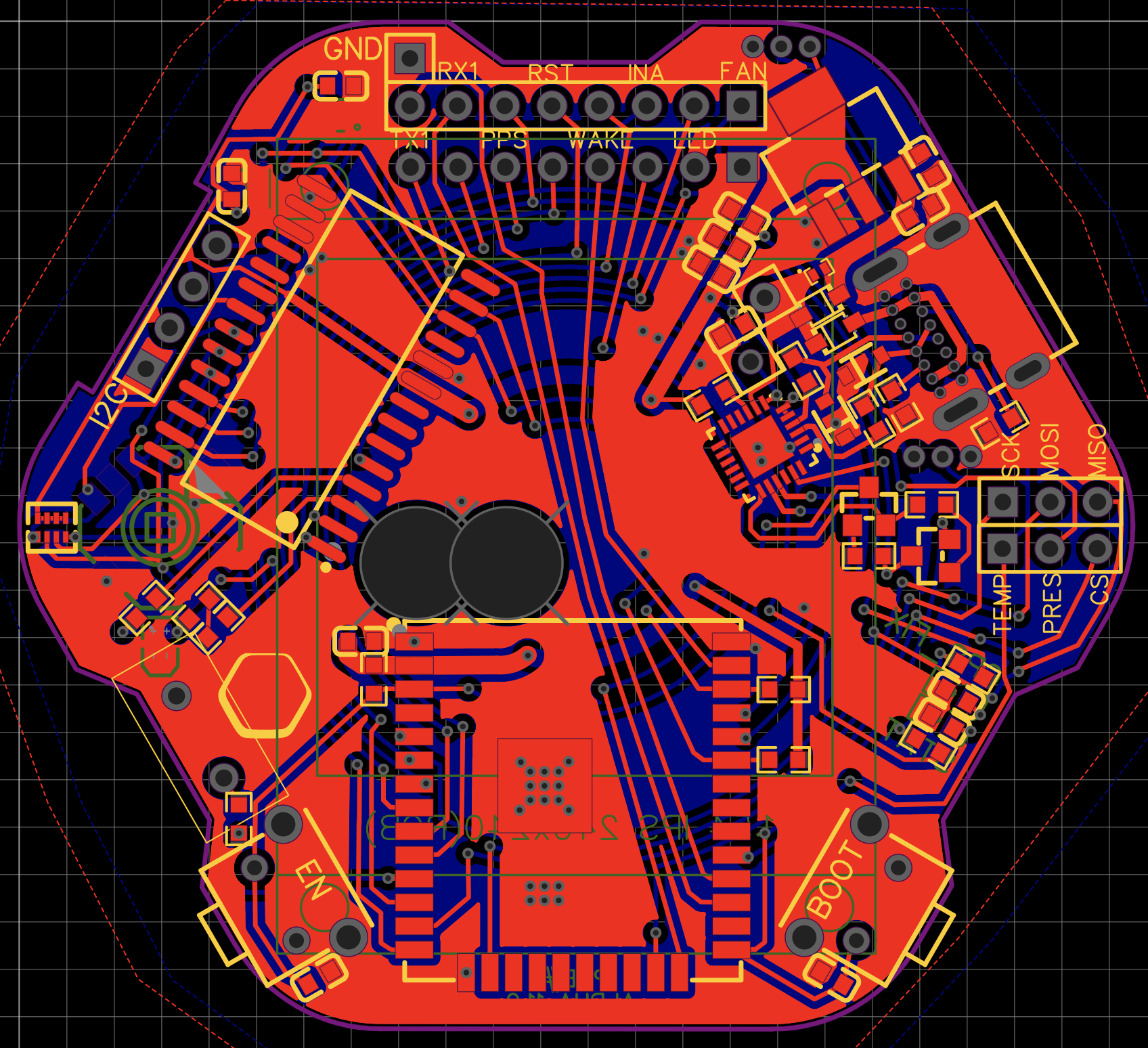
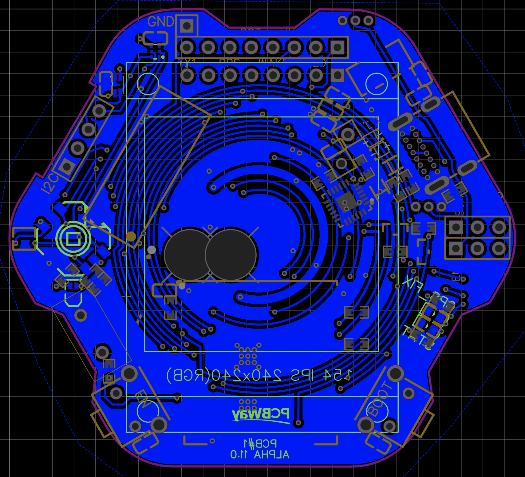
An update on my first testing with PCB design from version a11.0 to a11.1. First of all PCBway did a beautiful job manufacturing the PCBs! All errors and bugs are from my inexperienced design. Thanks to them for the support!
What worked:
ESP32
240x240px LCD Screen
USB-UART Bridge programming (only with reduced speed)
LEDs
Enable-, Boot Buttons, Auto-Reset
UV Sensors
What i did wrong:
the selected multiplexer PCF8575 only runs on 5v, but still worked on 3v3 as a LED sink
I2C bus was throwing errors at all speeds, probably trace interference
Serial upload threw errors sometimes, probably trace interference
selected wrong pins on ESP32 and TFT, had to bridge 2 to make it work
Assembly of the previous version 11.0, which you can see here. It had an unfixable error with the USB-UART Bridge and non-available multiplexer, so i went on to the next one. (always double-check the schematics!)
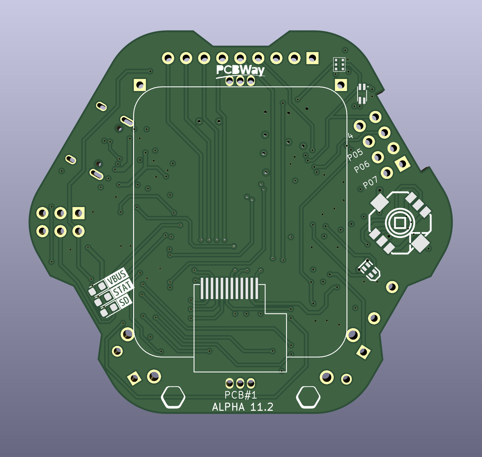
a fully redesigned Alpha 11.2 and testable working prototype
I got some help to do an overhaul of the entire pcb designs, to make sure they are properly designed and so i don't have to keep reiterating too many times. The power and lamp side with PCB#3 + 4 will have to wait for now.
Design is already done and to be sent out to PCBway for manufacturing. Again, great gratitude to them for sponsoring, couldn't do it without them!
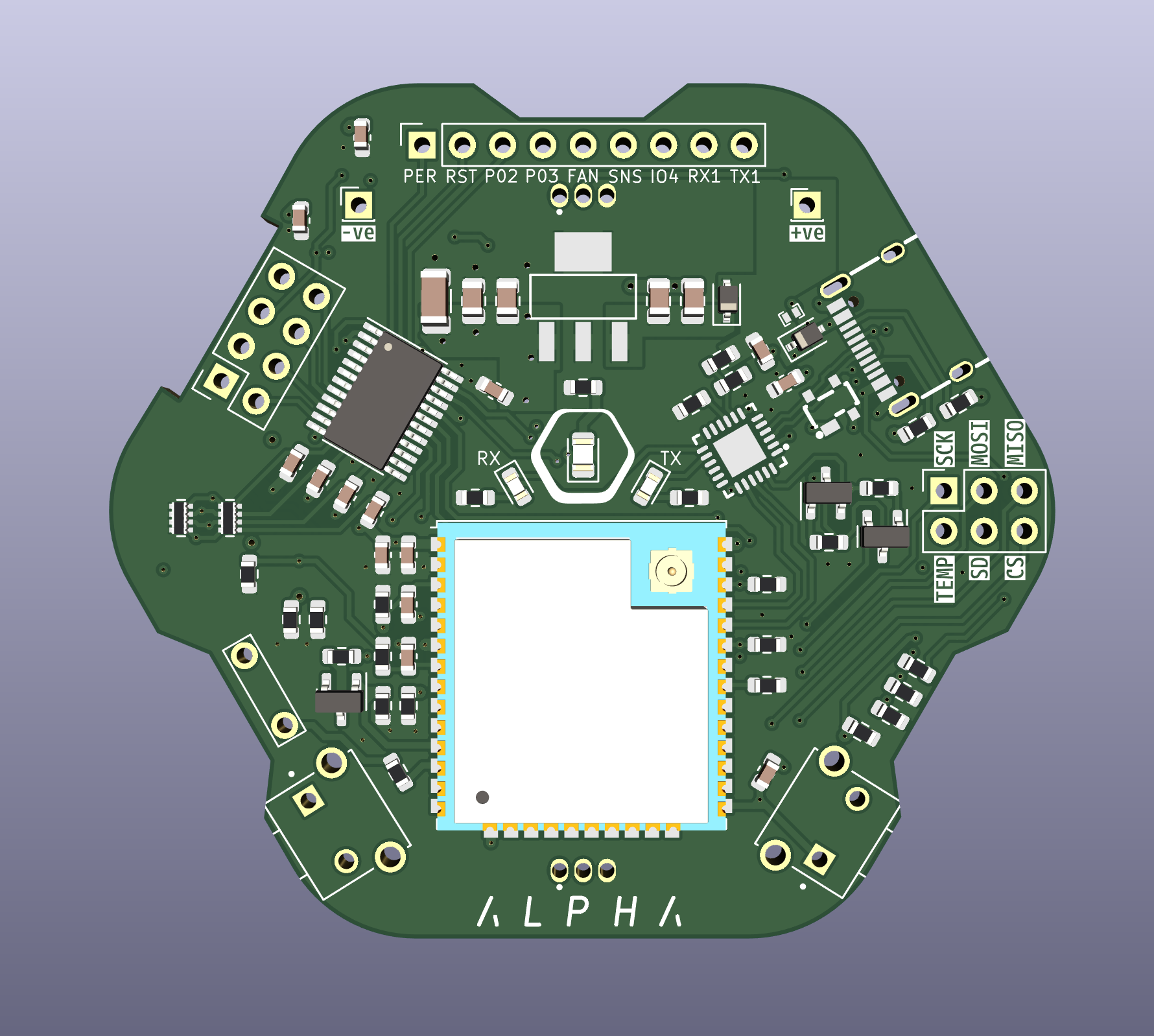
Alpha 11.2 Changes to PCB 1 + 2:
path / power path improvement
change PCB#1 to 4-layer design
switched PCF8575 to PCA9535PW
switched screen from 240x240px LCD to rounded bare240x280px LCD
all remaining IO broken out
switched GPS to M86-M33
added dedicated power off control to sensors and peripherals for extreme power saving
finished the design of PCB#1 (post coming soon) and sent it out to PCBway who were super fast and great!
It's been 3 weeks now, DHL decided to send the package on a little world tour (Shenzhen>Germany>Moldova>Romania>Italy>Germany) and now it seems to be stuck. But no biggie, i'm in Spain right now anyways, just hope i can persuade them to send it to me eventually. -.-
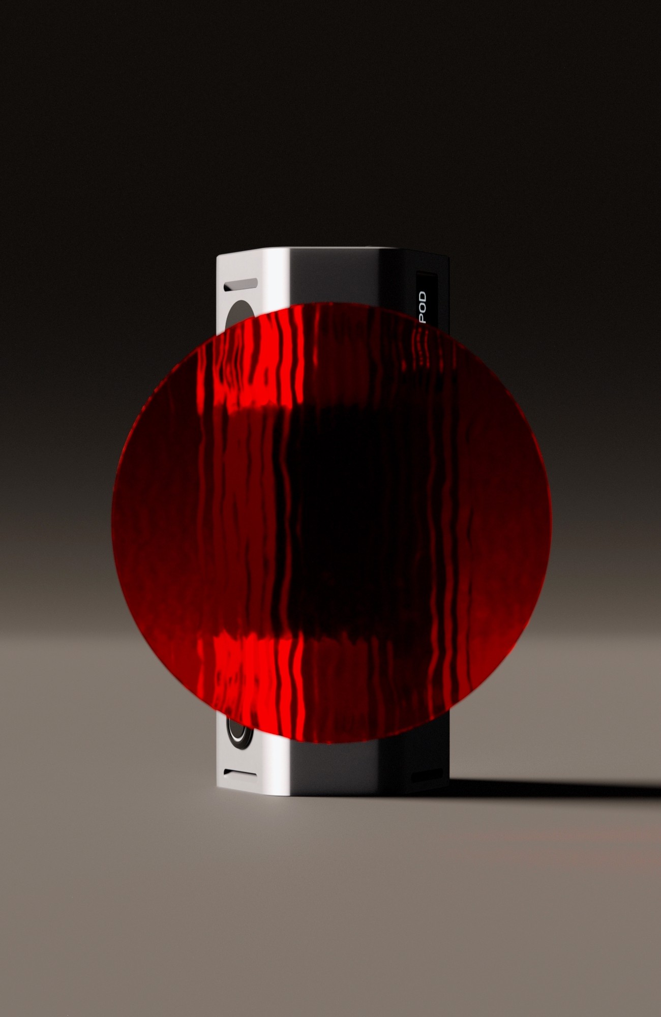
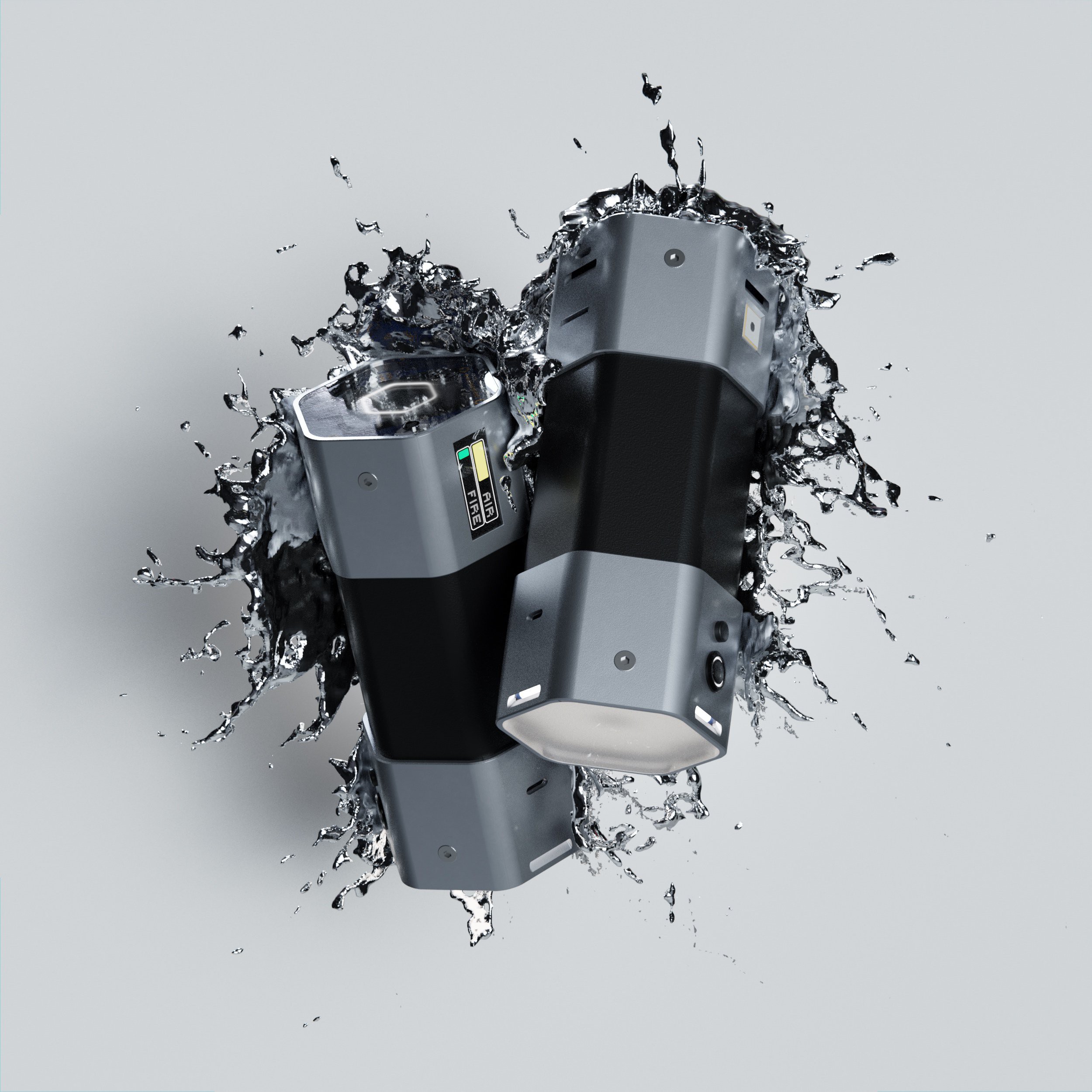
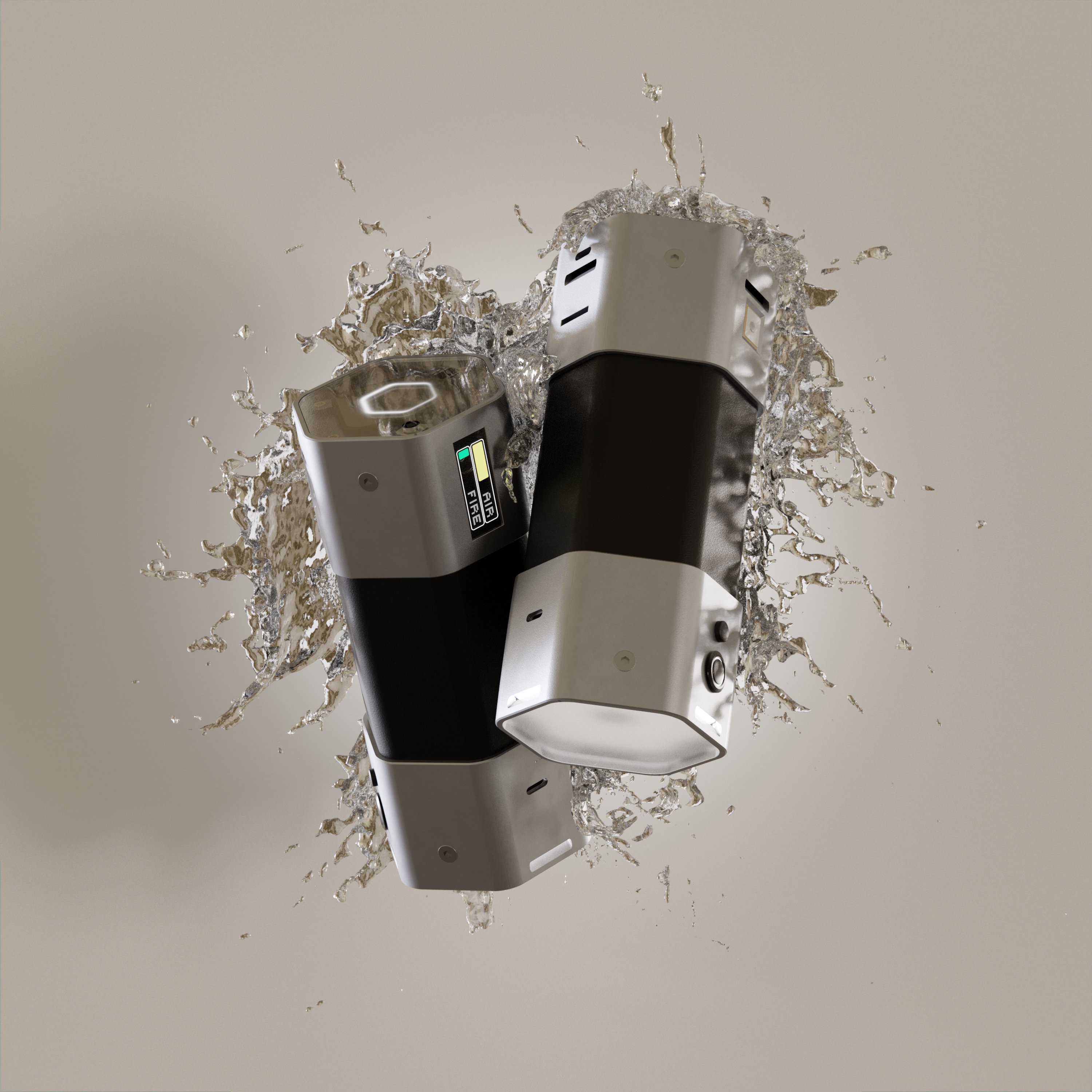
more Renders after the fold:
---------- more ----------
don't play with the solderit's actually not waterproof... yet.
I hit power path and size limitations with my breadboard prototype spider for while... and then i was offered sponsoring by PCBway. love when things come together by themselves.
So, i already started the PCB design and tests of the 3D printed enclosure. I scaled down the prototype a little bit. Basically temporarily taking out half of the battery, 1 sensor and the Spotlight LED. Makes it a much sleeker device and prototyping slightly easier. I can scale up again after the first successful PCBs. Gotta keep in mind that i want to keep it somewhat modular, space for expansion and user accessible.
Change-log [a10.2 -> alpha 11.0]
temporary Size cut-down
switch to customPCBs by PCBway
switch to 3D printing from Aluminium bracket design for now
switch to 4-way Joystick clickable with 2-Color LED
switch to BME688 T, H, P, AI Gas
switch to APDS-9250 RGB, ALS, IR Sensor
added MCU23017 I/O expander
added P82B715 I²C signal booster (if needed)
added MPU9250 back in (used to have I²C conflict)
removed VEML7700, BME390
PCB#1 Design
PCB#1 - ESP32, Multiplexer, Screens, User I/O, USB-C UART
PCB#2 - Sensors, GPS, SD card reader
PCB#3 - Power supply, BMS, USB-C controllers plugs, temp sensors
PCB#4 - LED matrix diffuse, PWM Led controllers, temp sensors, Thermal Camera?
thanks PCBway for sponsoring, excited to see the first one!
The other reason i had a bit of a break on this project is because i was stuck with the Aluminium part fabrication, so i finally bought an Ender 3v2 which will make the prototyping so much easier and faster. Also much easier to combine custom PCBs and 3D prints.
And also i built a DSLR Servo Follow Focus and a Cinema LED Panel in the meantime. good practice...
Code a10.2 - > alpha 11.0
Plan is to move to RTOS or Taskmanager based OS in this version (alpha 11.0). It will be built up from the ground to slim it up and make it more efficient. Getting to that after the PCBs are running.
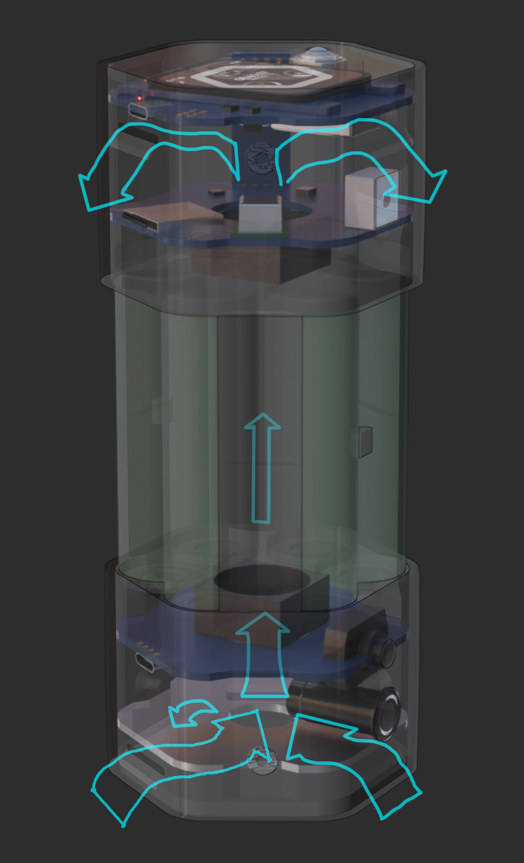
Airflow rough Sketch
shoot me a message if you want to join or help. peace
I've been working on the UI and made some progress i want to share.
Mainly Home and Menu Screens and some minor updates.
I realised i haven't featured the Air Quality/indirect virus detection theory functionality yet, that will be getting its own post soonish.
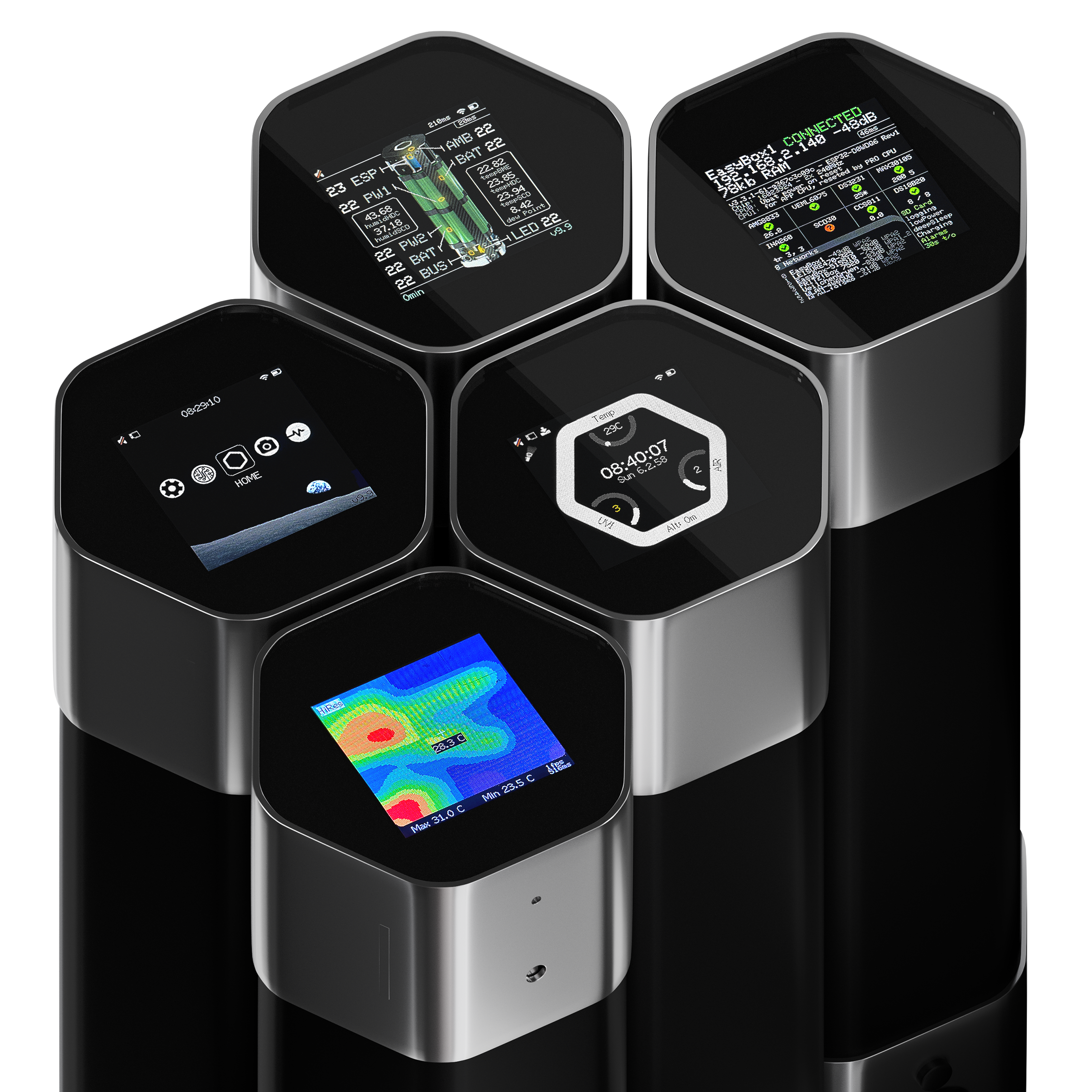
These are actual screenshots of the display (or photos rather, haven't figured out the eSPI screenshot readRect() code yet). Some pages are still cluttered and older, and i have yet to implement smooth fonts, but it's at a good state to show and explain.
---------- more ----------
* for the ones who haven't seen it in action: yt video at the bottom of the post.
Menu Screen
after booting up, we land on the Menu page, where we can navigate to the different screens. 9 in total with the sub-pages.
The Status Bar shows the systems stats when they are active or relevant: Time, Battery, WiFi, Mute, SD card, Logging, Fan, Air Quality Warning, Lamps, Low Power mode, Deep Sleep mode.
Notifications (IOS style) for different warnings, LED strength and other stuff. Wrote my own function that activates the notification, lets it stay for X seconds, retracts it and only returns when condition is true and after a determined amount of seconds.
(left to right) Diagnostics/Settings, System, Home Screen, Thermal Cam, Heart Rate
Home Screen
Shows the most important Data and Status Bar.
The three dials are: UV Index (left), Air Quality Index (right) and Temperature (top). Still debating on what data to display on these or if i should display even more data points. Colors of UV and AQI numbers change with severity of the danger levels.
Home screen also leads to CO2 and tVOC info page.
(don't mind the date, i'm definitely not from the future. you didn't see anything, move along)
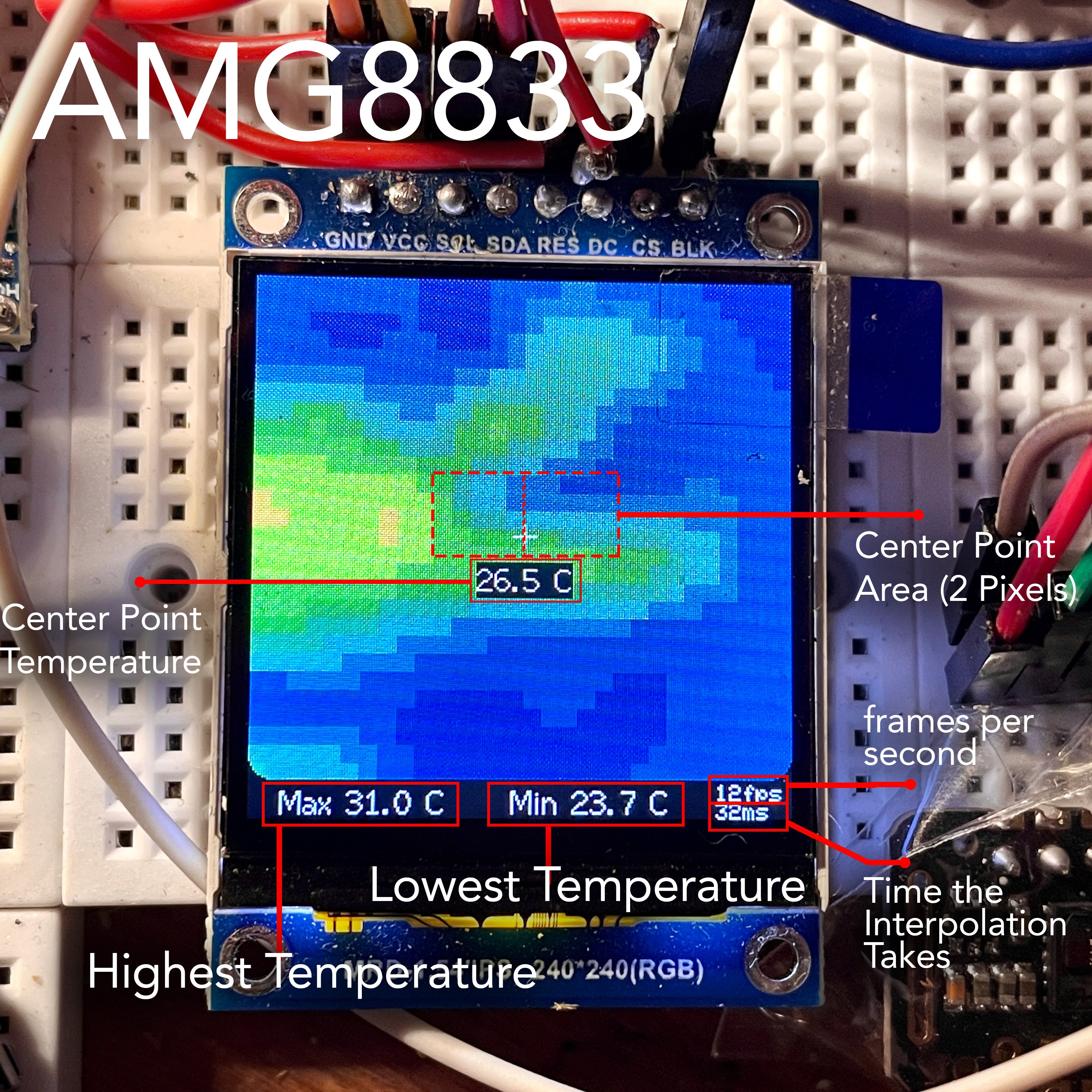
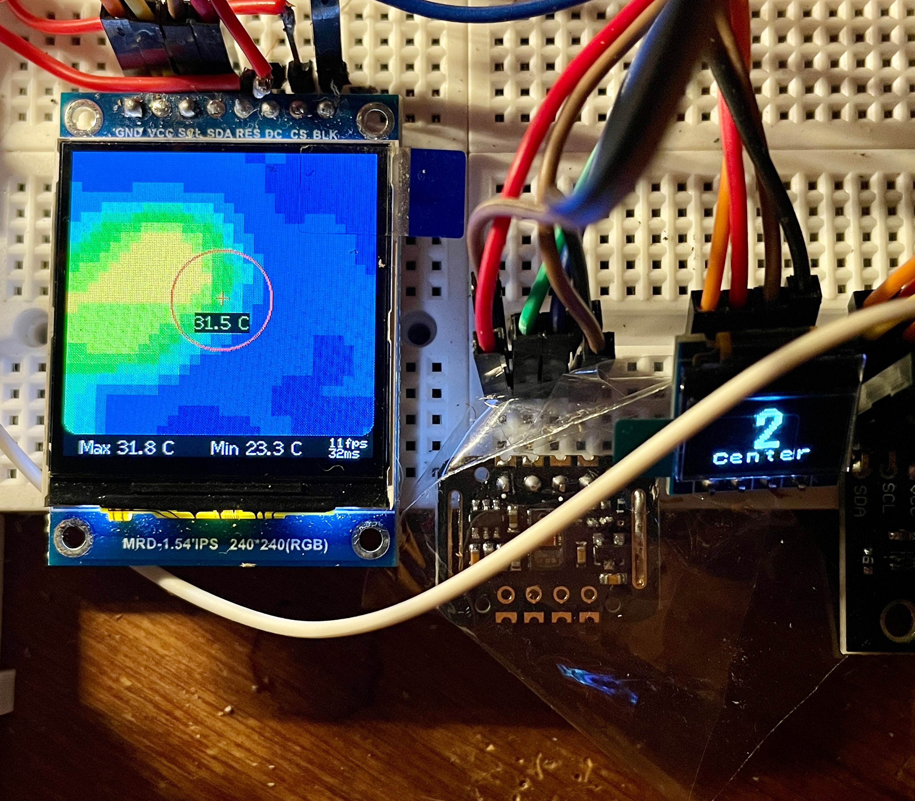
In short it features a Low Res (1 fps) and High Res (12 fps) mode and can do 3-sec burst averaging measurements of the highest seen temperature of the center area or the full screen.
System (revamp due)
will make this one less cluttered. Shows the exposed device and the temperature probes. Definitely more important for testing the limits of the H6X pod but will come in handy otherwise as well.
Had the idea to add detection and emergency shutdown for water ingress and critical humidity. Was thinking of using two exposed thin wires, almost touching, in areas where water could enter and sense when they short out.
- System screen leads to the Graphs Page.
Graphs (revamp due)
Shows graphs for Temp, Humidity, tVOC, CO2, Volts and Current. I will overhaul this screen soon. What i want to do is, access the logged data from the SD card and display a full day as it's advancing in bars instead of graphs.
Diagnostics
shows Status and configs of all Sensors, WiFi Stats and other things for debugging. page extends and scrolls
Heart Rate (revamp due)
since i worked on the UI, the measurement seems ¼ too low, and i don't know why. revamping the whole monitor is due.
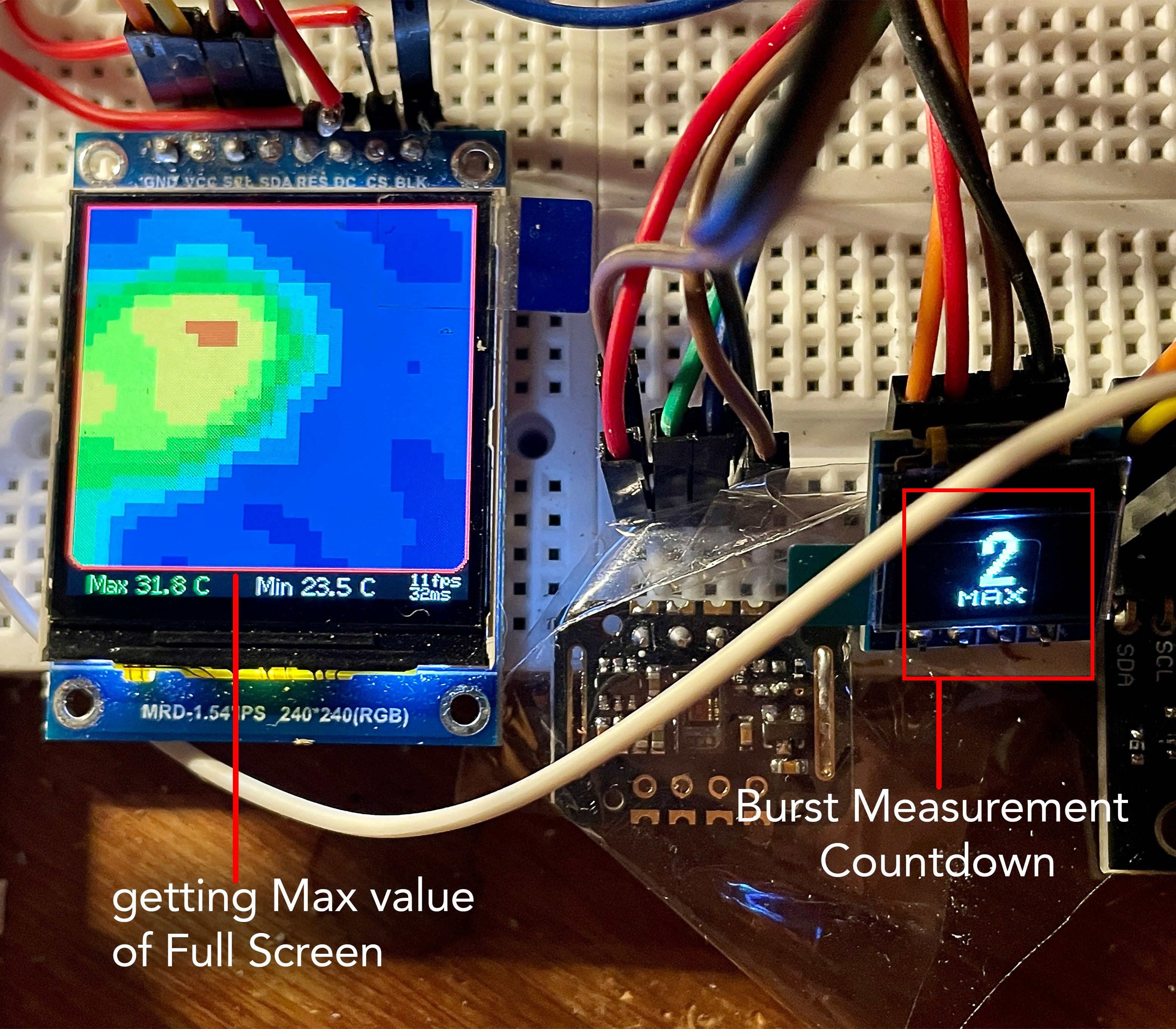
Full Screen burst mode collects the highest value out of the full array
Center Point burst mode collects the highest value out of the 2 center pixels
Button Single-Click: Trigger Burst Measurement (small 0.49" screen shows 3-sec countdown) Button Double-Click: Toggle Measurement Area (Center Point, Full Screen)
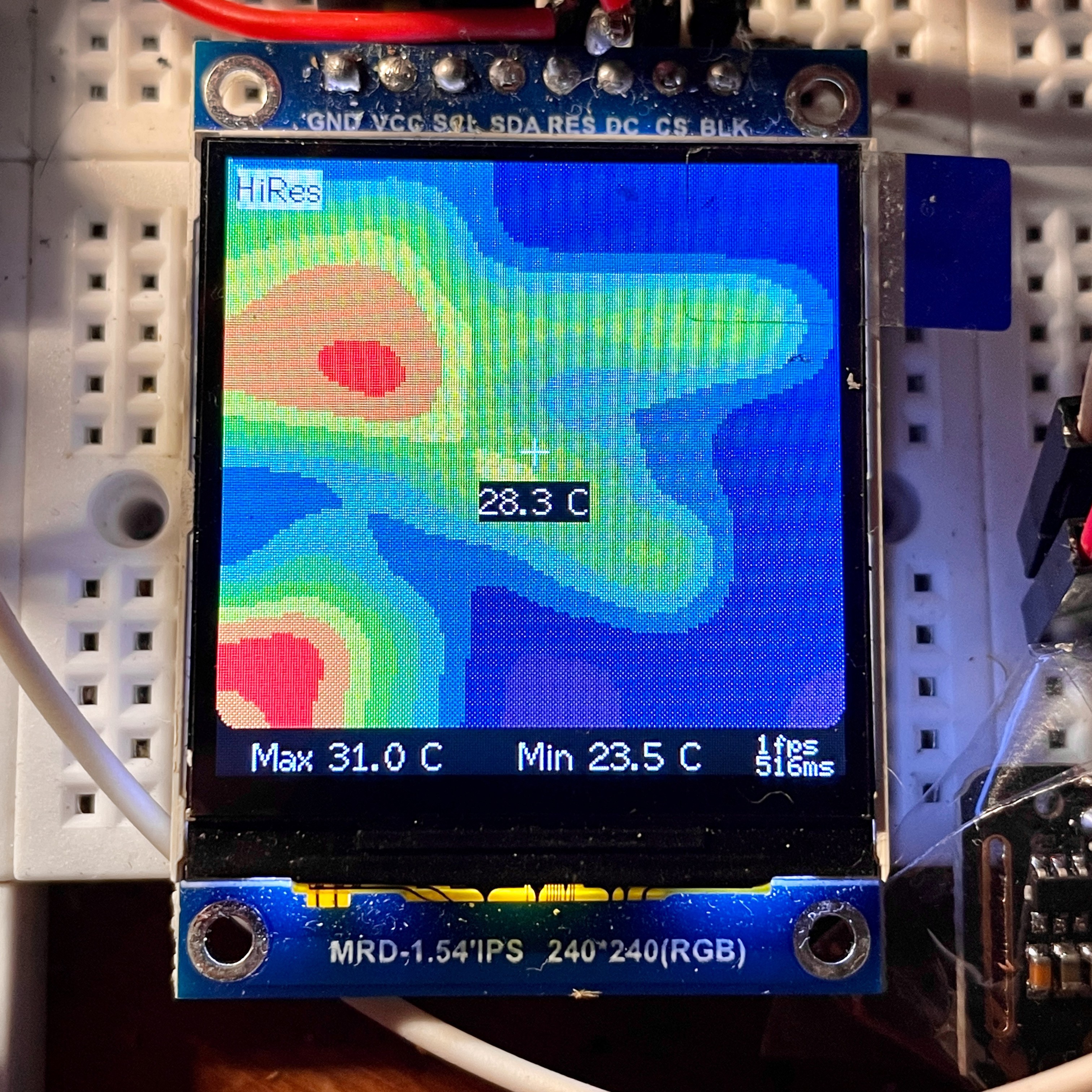
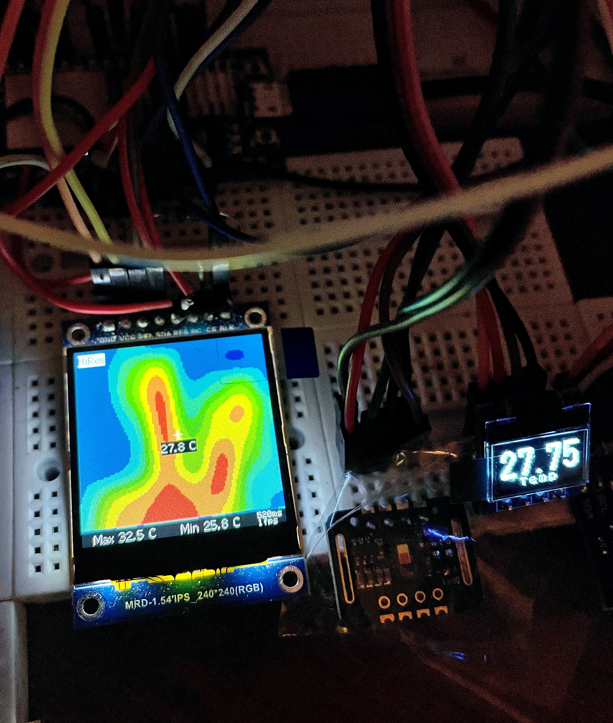
In HighRes mode i maxed out the Resolution so the frame Rate drops to 1. The Colour Temperatures are mapped to onscreen Min and Max Temps. Kinda works like a simple exposure compensation in a normal camera. The adjusted values get passed on to the LowRes mode if switched. Default temperature scale is 22C - 33C.
It features a Burst Mode (Averaging Mode) to get a more accurate reading with the 8 bit sensor values, by averaging 50 samples over 3 seconds. Measurement will always be taken from the highest temperature seen by the Sensors inside the selected Measurement Area (Full Screen (64px) or Center Point (2px)).
Issue: i can't, for the life of me, figure out how to access the full color spectrum to have smooth color transitions. I tried using the eSPI colors and a conversion method, but could only get it to work by accident with smooth colors going from dark blue to purple, and dropping 6 fps. no good. Could have something to do with the 16bit color mapping and how they are arranged in the array, since the actual 8x8 sensor values are 8-Bit, but the array only holds about 32 or 64 colors it looks like. i don't understand how to map the array correctly, or where to get a premade one.
more after the jump:
---------- more ----------
Burst Measurement Mode Full Screen:
In LowRes mode measurement happens while displaying. In HiRes mode no displaying is happening during measuring, because we are displaying at 1 fps. So it is a true burst reading, only acquiring data and then going back to displaying, and is much faster because of that (ca 1 sec, 50 samples). Temp Numbers are still being updated and last image stays on screen.
Update: Time for some pictures of Hardware implementation and UI progress:
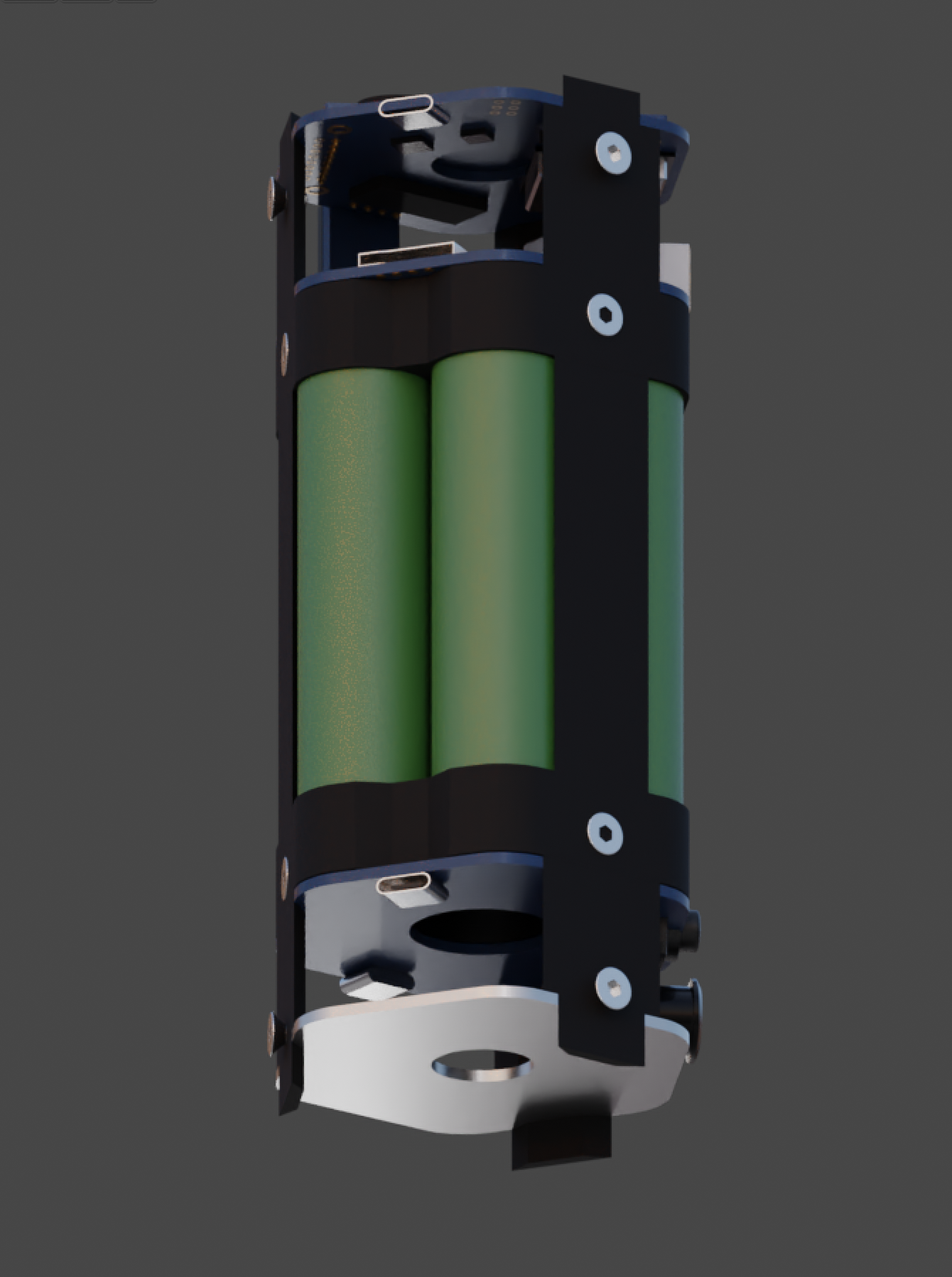
Layout of Battery pack, power & charging boards inside the Thermal Duct, that the empty battery slot creates. Components are mounted on Aluminium heatsink that goes from top to bottom with maximum exposed surfaces to the Airflow. There are two levels of PCBs in this design. 3x 2S 2A Chargers(?), 4x 3A voltage buck converters, INA219 + INA260, 400w PWM Controller, 2S 20A Protection/Balance Board. Hoping Air will still flow ok. Also still figuring out the power path for charging. Loading Screen (random selection of 12 different screens), shows loading errors and reset reason
Progress with the UI:
It's still not very beautiful, but already does almost everything that was planned.
Battery Pack tinkering & Electronics PrototypeHome Screen displays most important Sensor Data. The whole System has a warning Screen for critical Over/Under - Temperature, Voltage, Current, Wetness values and sets everything into Low Power / deepSleep modes. Phone-like Status Bar for SD card, Logging, Fan, WiFi, Battery, FPS, Lamp, time since reboot. Small 0.49" Screen cycles through sensor values, shows alarms and indicates charging.
---------- more ----------
Heart Rate & Blood Oxygen Monitor. Diffuse LED swells and beeper indicates Heartbeat as well Small 0.49" Screen shows Heart Rate BPMData Graphs (CO2, VOC, Voltage, Amps, Fan State, Temp, Humid) (CCS811 is freaking out here because of the voltage drops) Small 0.49" Screen cycles through sensor values, shows alarms and indicates charging.System Status, WiFi, Debug (re-initializes sensors in case of error)CO2 Info screen. Small 0.49" Screen shows CO2.
there is also a total VOC screen and a Thermal Cam screen, but im still waiting for the AMG8833.
 eBender
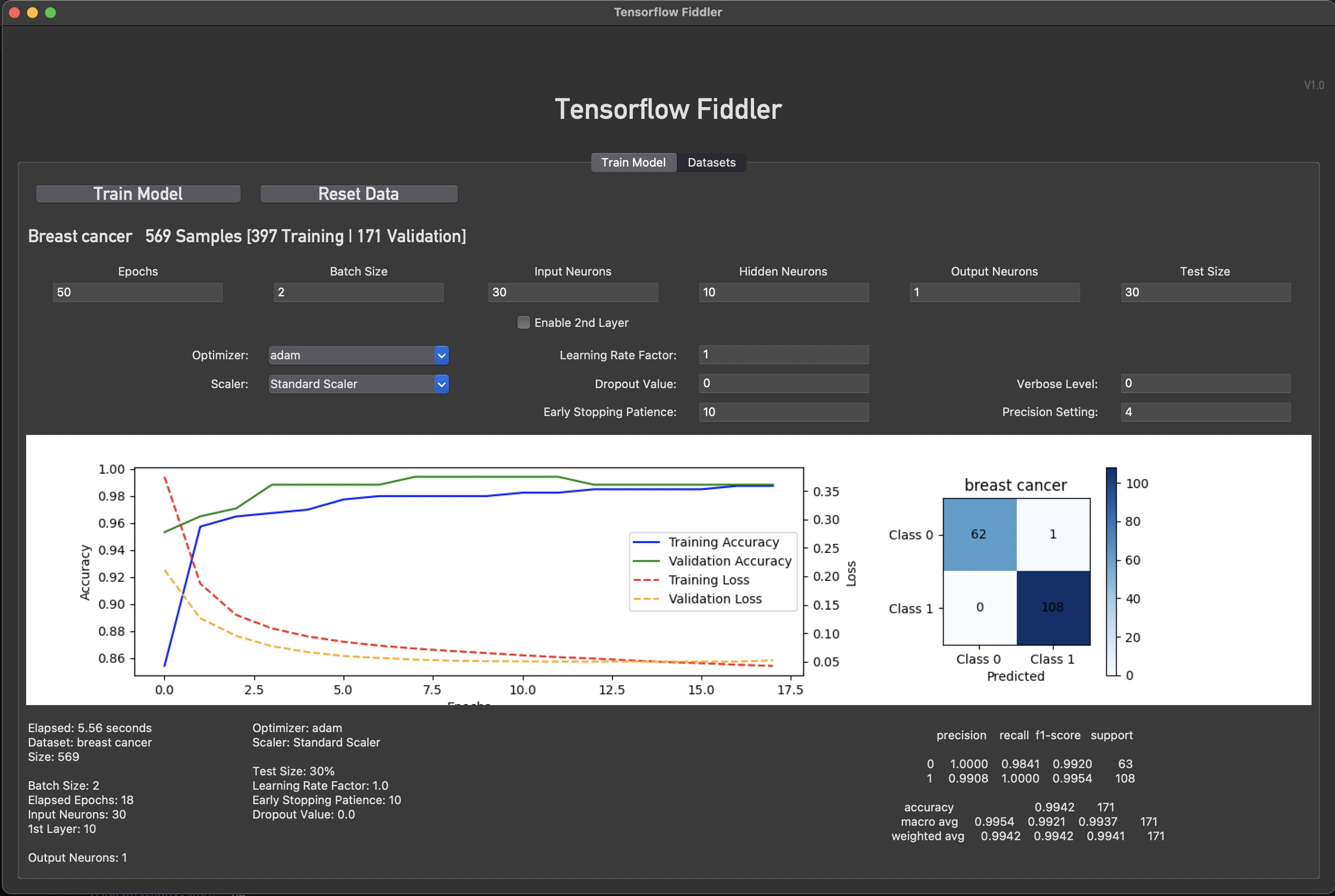 This is the first app that i programmed ever. In a language that i have never written in before (python).
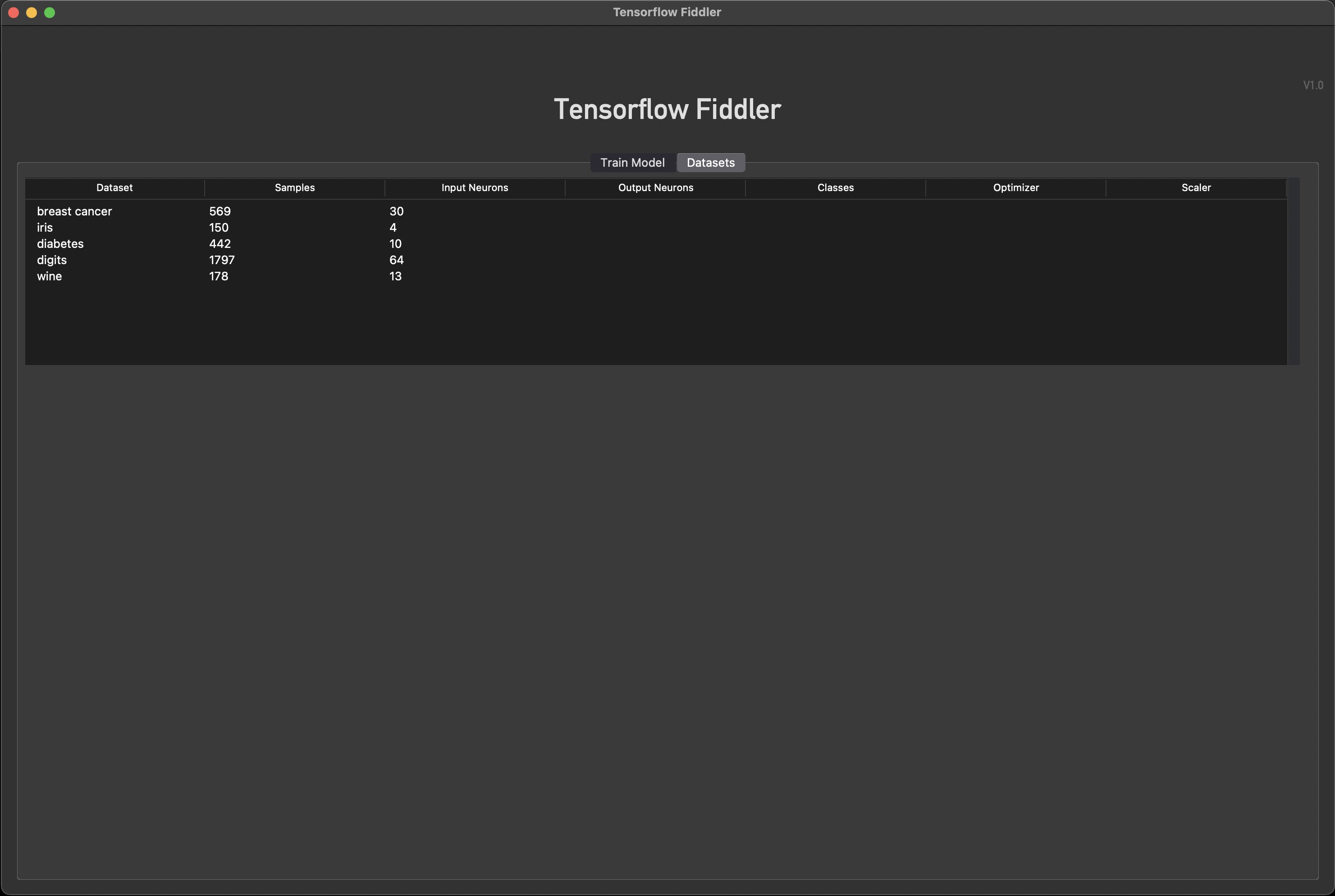


 These are actual screenshots of the display (or photos rather, haven't figured out the eSPI screenshot readRect() code yet). Some pages are still cluttered and older, and i have yet to implement smooth fonts, but it's at a good state to show and explain.


")
")
")
")


")


")

