 finallyfunctional
-
1Before you start
Prerequisite reading
Before you buy the parts and tools to build this rig, please carefully read through the following.
- By reading these instructions and/or building this VR support rig, you agree to my liability disclaimer.
- Please read this log on if you should even build this rig and VR shoes.
- This setup is meant to be used with one of my safety support rigs. I currently have a ceiling mounted rig and a free standing rig. You can read my comparison of the two here.
- This rig has a feature list on its project page, in the description.
- I used a specific half-body safety harness for my build (row 53 in the BOM). It couples to the rest of the rig in a specific way. If you use a different climbing harness with a different design, you may need to figure out a different way of coupling it to the rest of the rig.
Again, please read everything above before you spend the money on the parts for this and the time building this setup. My setup is niche and not for everyone.
3D printed parts
I printed almost all the parts out of TPU with these settings. A few parts were printed with PETG, and these settings should work with those too. Instead of PETG, ABS or PLA could also be used.
- Layer height: 0.2mm
- Perimeters: 3
- Top and bottom layers: 3
- Infill: 20% rectilinear
Ready? Lets Go!
Here is the BOM with parts, tools, and prices. 3D model files are here.
I encourage you to read through all the instructions here before you assemble anything to make sure you have a clear understanding of what each step's purpose is and how it fits into the whole assembly.
-
2Attach top of front stopper to front part of VR shoe
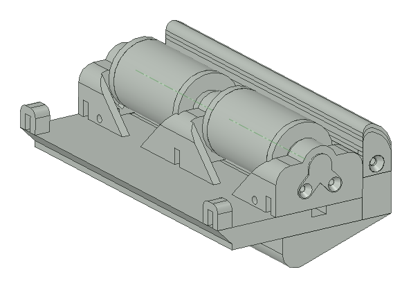
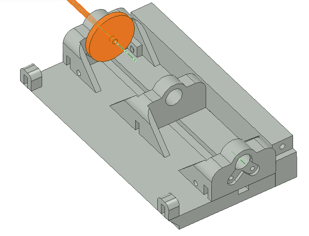
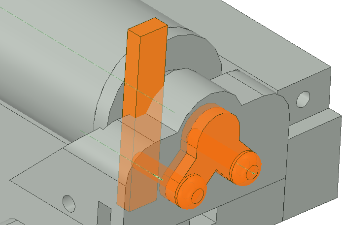
In the first several steps we will be assembling the front of the VR shoe, shown below.
![]()
First, attach the top of the front stopper (row 3) to the front of the VR shoe (row 2) using two square nuts (row 15) and two 6-32, 0.75in long screws (row 14), as shown below.
![]()
![]()
Future Improvement
Just a note on a future improvement. I had square nuts I bought from McMaster-Carr for very cheap when I build my VR shoes, so I used them. Most of the spots where nuts are used, they are inserted into a 3D printed part. The 3D printed part keeps them from turning when a screw is tightened to the nut, and square nuts were a little better for this than hex nuts.
While putting together the BOM for this project, I noticed that square nuts are more expensive on other sites. So when I make improvements to this design I'm going to replace the square nuts with regular hex nuts.
-
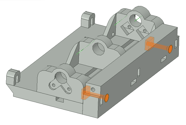
3Place square nuts for axle caps
Insert four square nuts (row 15) into the square holes as shown below.
![]()
-
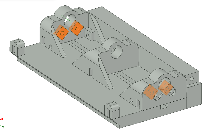
4Insert 3mm bearings
Take two 3mm bearings and insert them as shown below. Two go in each axle support. You'll put two more 3mm bearings in the 2nd and 3rd axle support later.
![]()
-
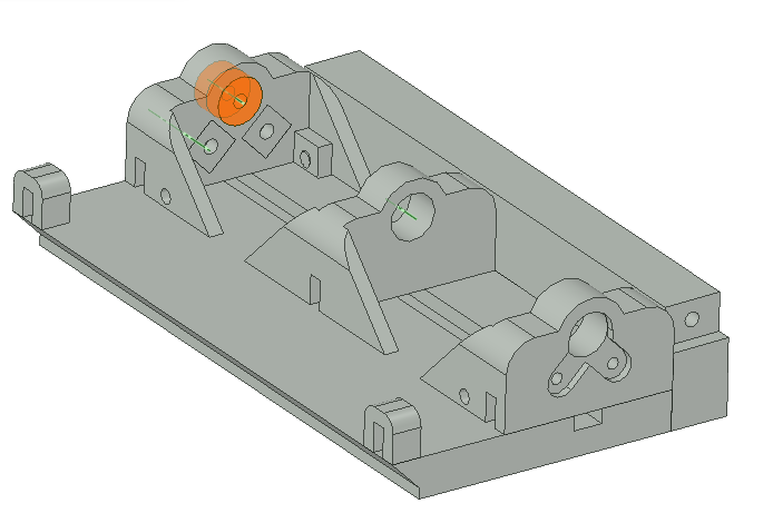
5Start inserting 3mm rod
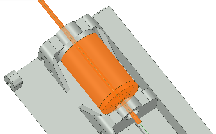
Take your 3mm rod (row 10) and cut six pieces that are 4.875in long. Take one of those pieces and slide one end through the 3mm bearings. Take one of the wheel ends (row 12) and slide it onto the rod, as shown below.
![]()
-
6Slide wheel onto rod
Take a wheel (row 11) and another wheel end (row 12) and slide it onto the 3mm rod. Keep pushing the 3mm rod until it's through the middle axle support.
![]()
-
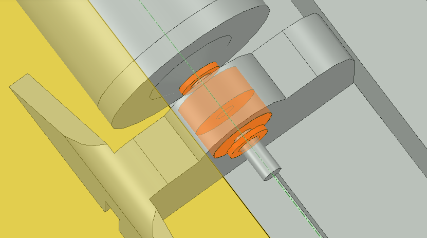
7Slide spacers and middle bearings onto rod
Slide a wheel spacer (row 13) onto the rod, followed by two 3mm bearings (row 9), and finally another wheel spacer.
![]()
-
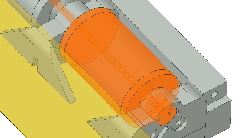
8Slide second wheel onto rod
Slide another wheel end (row 12), wheel (row 11), and another wheel end onto the rod. Push the rod all the way through as shown below and put two more 3mm bearings (row 9) on the end.
![]()
-
9Add caps to keep rod from coming out
Take an axle cap (row 8) and insert it on the side as shown below. Take two screws (row 17) and screw the axle cap onto the side. I found that the square nuts on the other side of the axle support can be pushed out, so I ended up taking a piece of the rectangular rod (row 16) and shoving it alongside the square nut as shown below, to keep the nut in place, then twisting the screw in. You could also use a thin screwdriver or probably a 3mm rod to hold the nut in place.
![]()
Future Improvement
In the future I'm planning on redesigning the axle supports so that it's easier to screw the caps on, or possibly eliminate the caps altogether.
-
10Attach bottom of stopper
Take a bottom stopper piece (row 4) and screw it on as shown below, with two screws (row 14).
![]()
Row 6 and row 7 are bottom stopper pieces that are a little longer, so they will hit the ground easier once the shoe is tilted up while walking. I like the shortest one, but others may like one of these other options.
Passive Virtual Reality Shoes
I'm making a shoe that allow you to walk around as much as you want in VR while staying in the same spot in real life


Discussions
Become a Hackaday.io Member
Create an account to leave a comment. Already have an account? Log In.