-
1Program the Arduino Nano
Program the Arduino Nano with the attached footswitch.ino sketch. You might have to remove the include if you're using Arduino IDE (I use PlatformIO).
-
2Drill a hole for the connector and install it
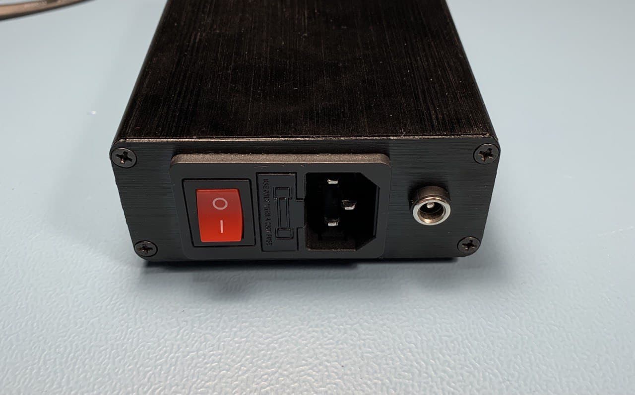
Drill a hole in the case for the connector. I found that there's plenty of space at the back of the case. It's aluminium, so make sure you have a sharp metal drill bit, and don't spin the drill too fast. I used a 4mm pilot hole and finished it with an 8mm drill. Make sure the aluminium chips don't go everywhere.
![]()
-
3Print the bracket for the Arduino Nano and mount it in the case
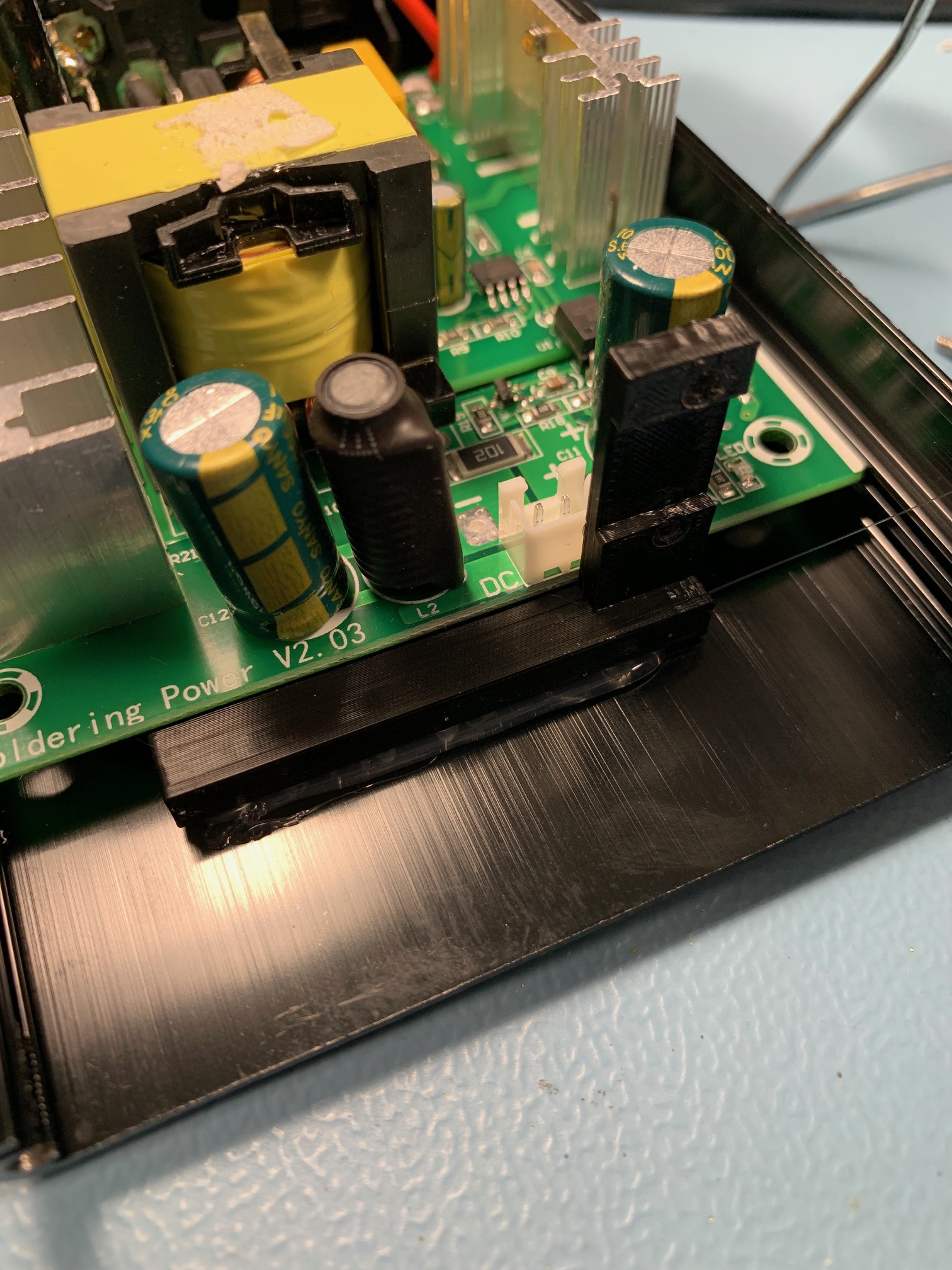
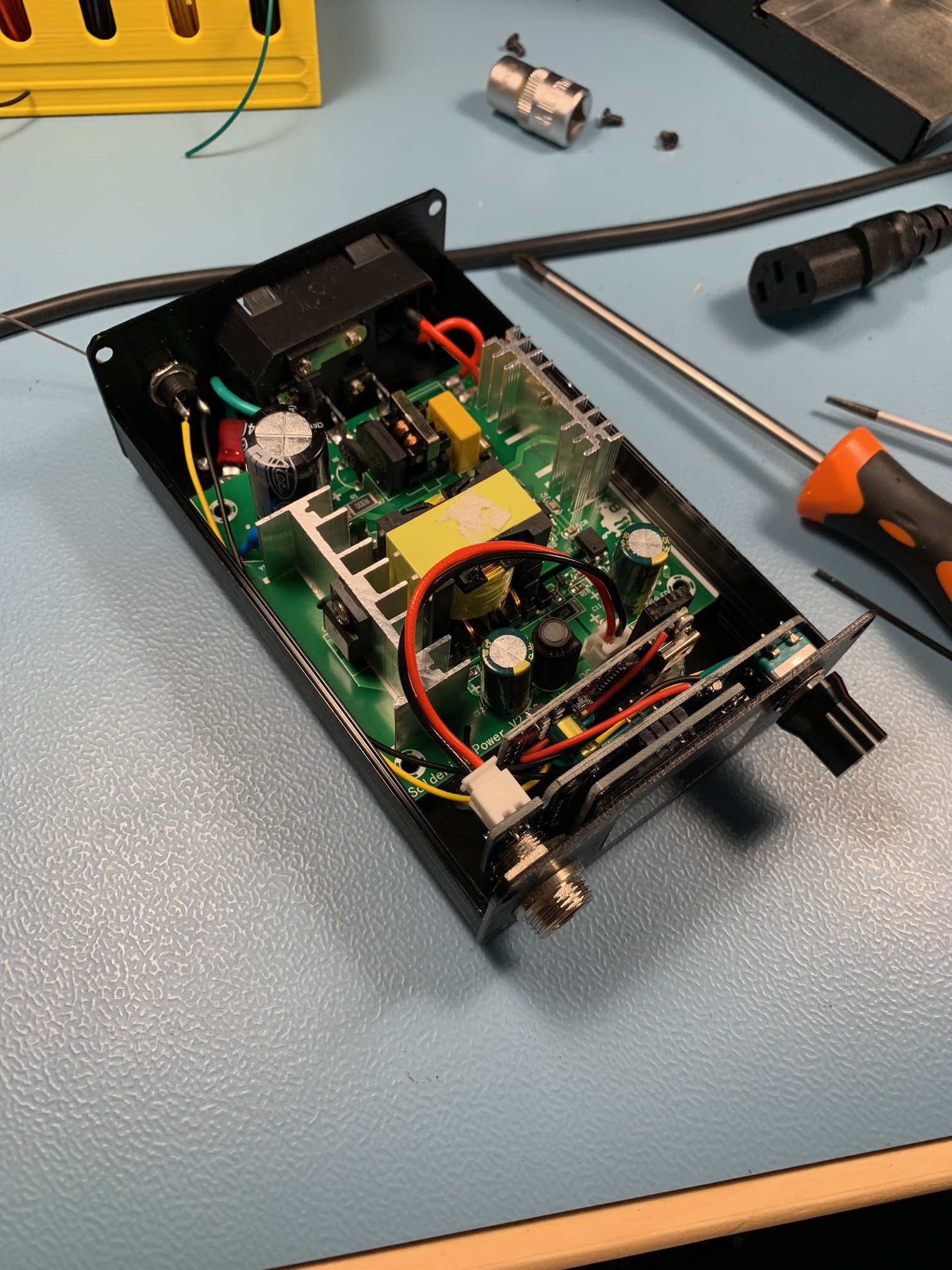
Print the bracket for the Arduino Nano (STL included). It's fine to use whatever plastic for this (I used PLA). After printing, mount it inside the case using hot glue, but make sure to work quickly as the aluminium case sinks heat really well. You can mount the bracket right up to the existing PCB
-
4Wire up the Arduino to the control board and connector on the back
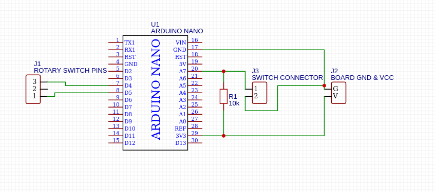
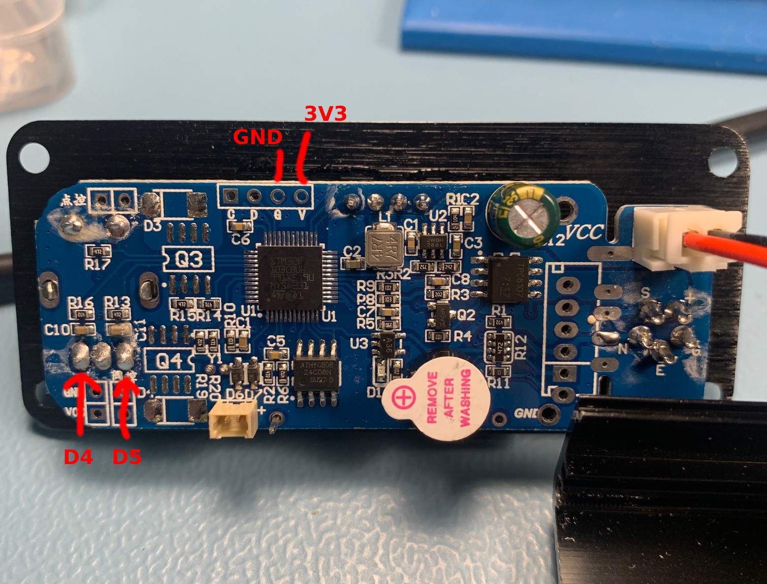
Wire up the Arduino according to the schematic below. The pins on the controller board can be identified with the picture below. I found that when powering the Arduino Nano from 3.3v directly, the internal pull-up resistor doesn't work reliably, so I've added an extra 10K resistor for pull-up.
![]()
-
5Wire up the foot switch
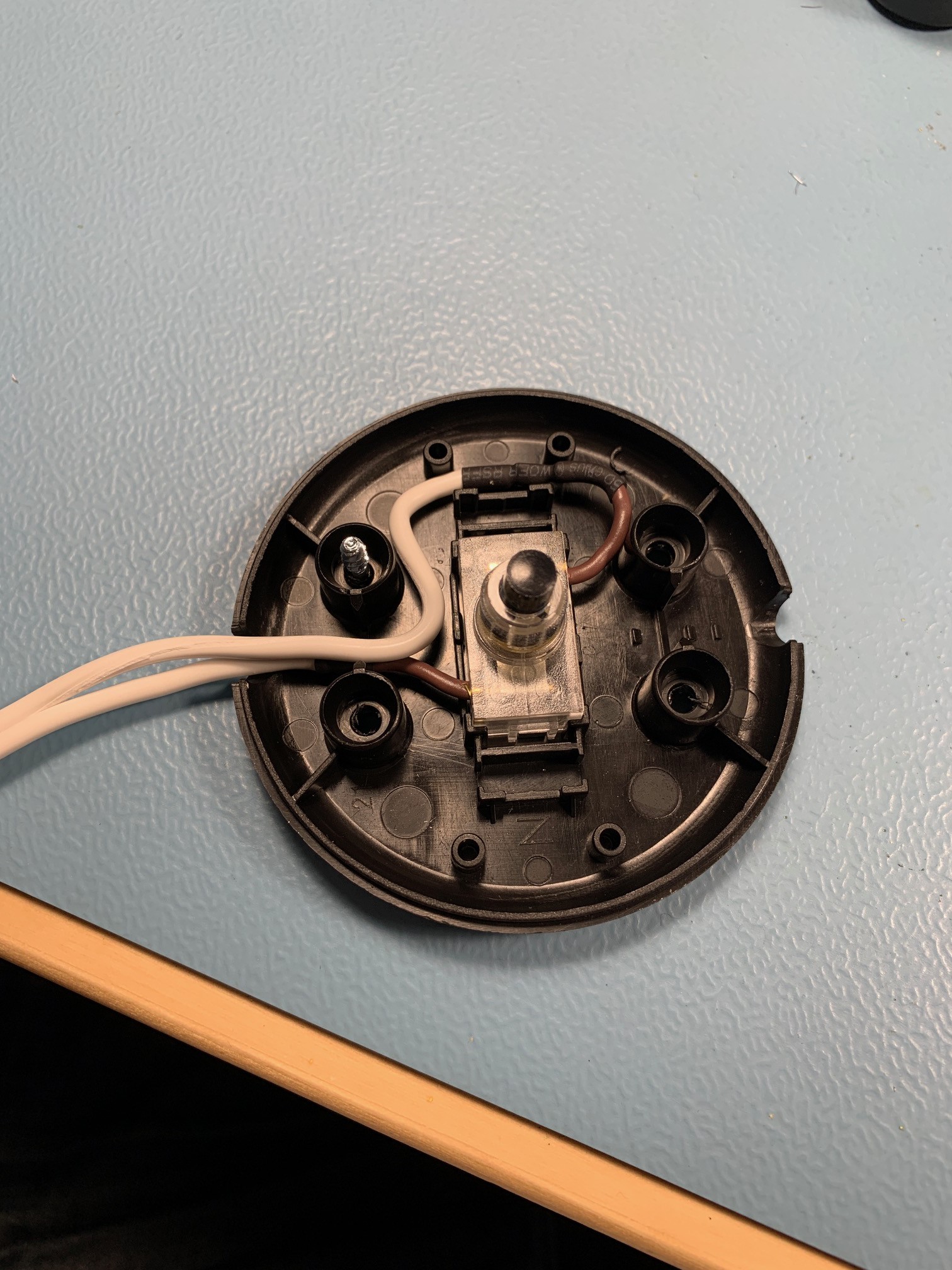
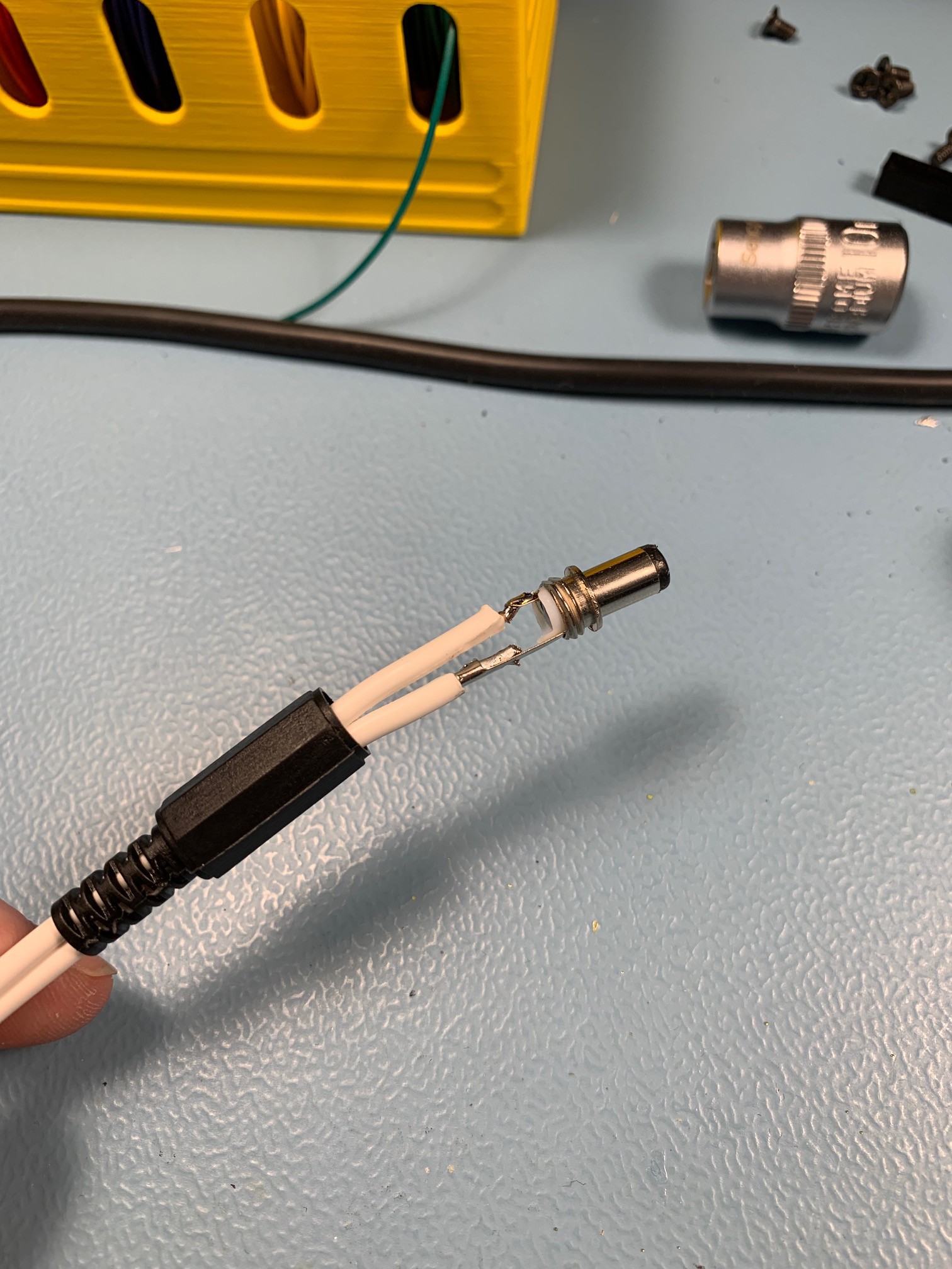
Wire up the foot switch with the connector of choice.
-
6Install the Arduino Nano in the case
Using two M2x5 nuts and bolts, mount the Arduino Nano on the bracket and reinstall the front panel.
KSGER T12 Foot Pedal
A foot pedal mod for the popular KSGER T12 soldering stations to control the boost function for temporary power.
 Merijntje Tak
Discussions
Become a Hackaday.io Member
Create an account to leave a comment. Already have an account? Log In.