Close
0%
0%

Pocket-Sized Imsai-Style Z80 Board

Similar to the old IMSAI 8080, but small enough to fit in your pocket :)

Similar projects worth following
Implementing a single-board pocket-sized (about 3"x4") rechargeable version of the old IMSAI 8080. Not trying to make an exact clone: just something (Z80-based) with similar interactions. Basically a way for students, hobbyists or anyone interested in computers and hardware to watch a CPU running one step at a time, examine and change memory, load and execute code, and have a lot of fun hacking at a machine-code level.

See https://gitlab.com/nickmacias/Z80SBC for the most-complete description of details.

The Version 2 board is complete!

This is a 4-layer PCB, and includes WiFi support, as well as headers for accessing all Z80 signals.

There is a draft of a user manual available here. There are numerous improvements to the CLI, and the general management of the Z80.
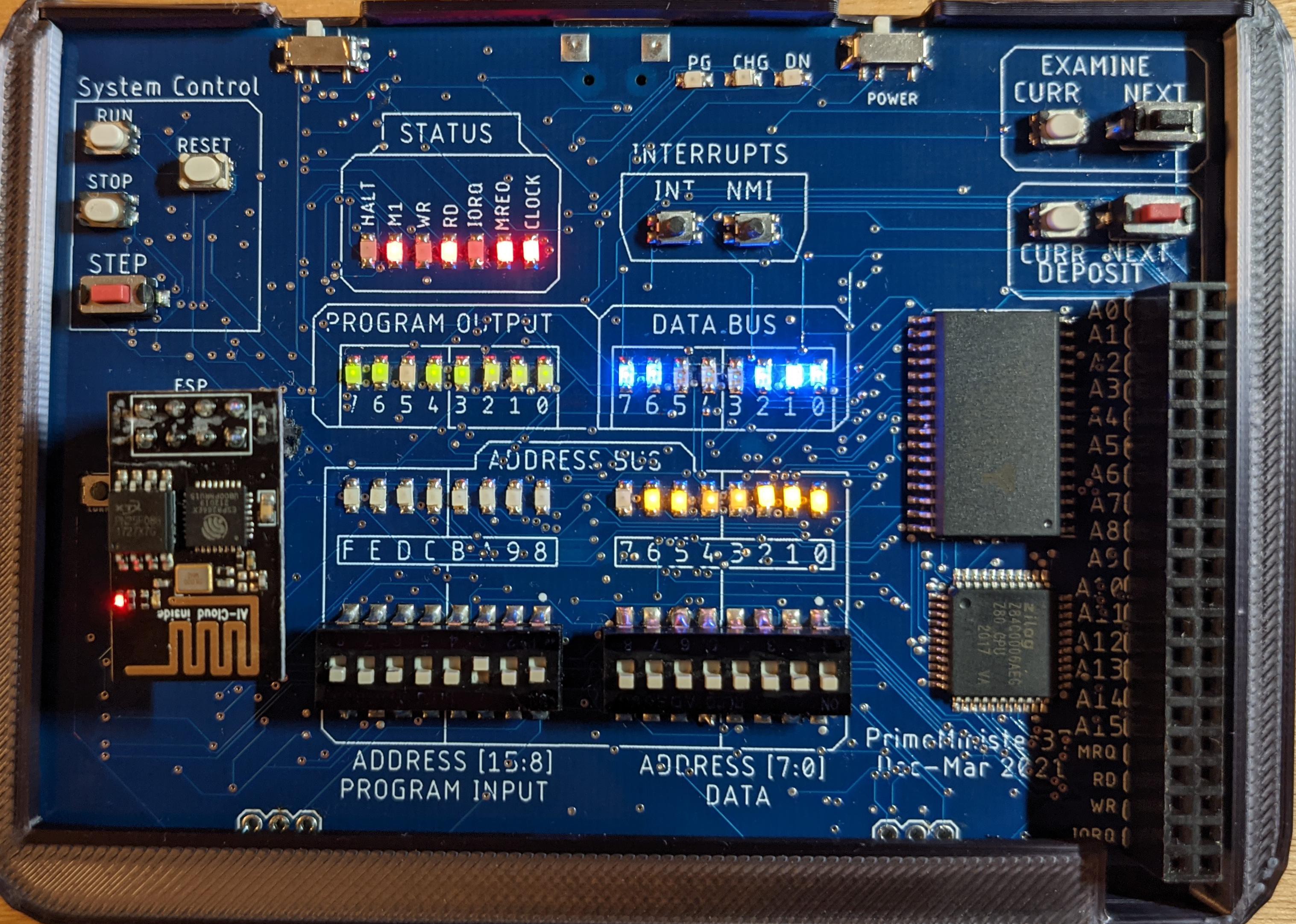
Runnable jar file and source code for the loader are available here.

Source code for the ATMega328 controller is here.

Board files - PDFs of the schematic, top and bottom of the board; as well as Eagle .brd and .sch files are available hereNOTE: The current version (A045) includes a bug in the I/O port addressing: a jumper wire is needed to restore addressability. This will be fixed in a subsequent version.
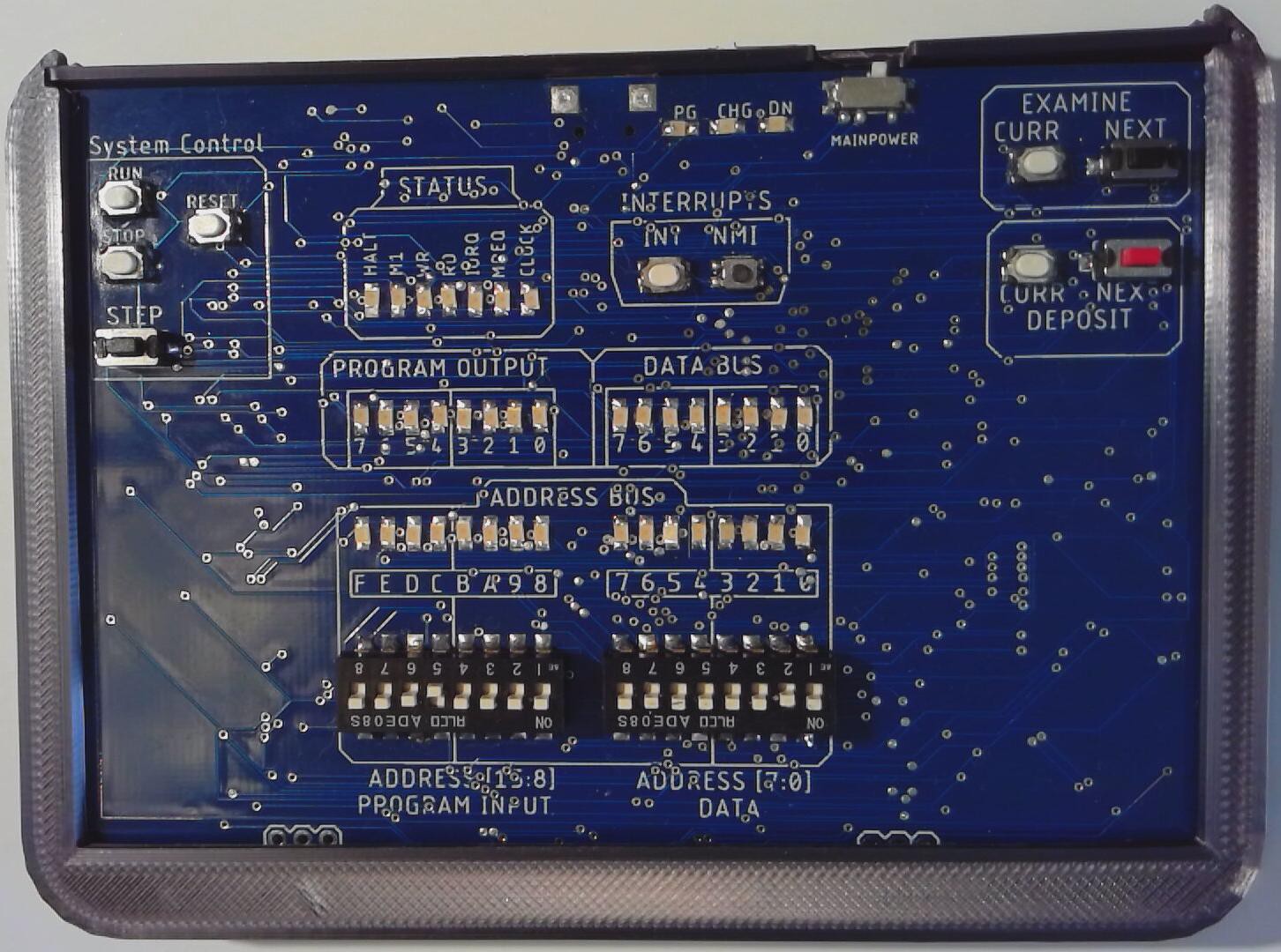

Assembled First Version
Version 1 - Fully Functional!

The main purpose of this project is to have fun soldering lots of tiny components onto a PCB :) The secondary purpose is to implement a pocket-sized system similar to the old IMSAI 8080
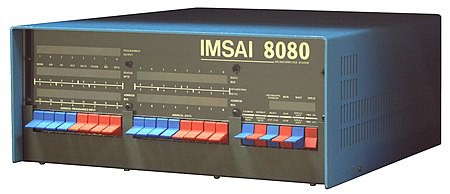
Original IMSAI 8080
An inspiration for this project :)

allowing front-panel manipulation and exploration of machine code.

Main Goals (form the original system):

  • ability to enter and examine code via front panel switches
  • display of address bus, data buse and system signals via banks of LEDs
  • deposit Next/Examine Next option
  • system can be in RUN or STOP state (different from HALT)
  • input and output of user data (IN and OUT instructions)
  • ability to single-step the CPU

Additional goals beyond the original system:

  • pocket-sized
  • rechargable
  • Z80-based
  • ability to save/restore main memory in non-volatile storage
  • full system control (including a basic disassembler) through a command line interface via USB port
  • multiple granularity of single-step (T-cycle, M-cycle, M1-cycle)

Wish-List (implemented in prototype to varying degrees):

  • WiFi support (DONE)
  • Allowing access to bus signals via headers (DONE)
  • Make use of ATMega328's flash to save configuration info: default step size, default radix, power-up running or stopped, etc. Also give user the option to load (and optionally run) from flash on power-up.

Out of scope:

  • S-100 bus (not implementing this)
  • Peripherals
  • most anything else I haven't thought of!

Notes 2021-03-24.pdf

Circuit diagrams and code mods for interfacing Z80 Tine BASIC to the terminal system.

Adobe Portable Document Format - 505.68 kB - 03/25/2021 at 08:49

Preview

Z80KB.ino

Arduino code for simple terminal program.

ino - 2.47 kB - 03/25/2021 at 08:48

Download

all.pdf

Personal notes from which the entire thing was built. These turned into the breadboard, and eventually the schematics and PCB in Eagle. I used to generate boxes of notebooks with things like this in them. Now they're mostly stored electronically :)

Adobe Portable Document Format - 12.78 MB - 03/03/2021 at 23:21

Preview

whole shebang 2.jpg

The mostly-finished prototype. Lots of board capacitances/voltage drops/etc. but has worked remarkably well for a 4MHz circuit!

JPEG Image - 3.37 MB - 03/03/2021 at 22:43

Preview

wall art.jpg

Always a fan of wall art - this is the PCB layout (component side) for eventual assembly.

JPEG Image - 2.81 MB - 03/03/2021 at 22:43

Preview

View all 22 files

  • GITLab Repo Updated

    Nick04/13/2021 at 03:53 0 comments

    I've made a new repo on GITLab with everything I can think of collected in one place. The README is fairly extensive.

  • PS/2 Pain and Suffering and Happiness

    Nick04/12/2021 at 18:42 0 comments

    PS/2 keyboards are awesome - super cheap (a few bucks from a thrift store!) and easy to interface with - clock and data, sample the data when the clock ticks, build a word, and you've got a scan code. There's work to do in converting scan codes, treating SHIFT etc correctly, and so on. Fortunately, there are Arduino libraries that make this all pretty simple.

    I started with https://github.com/PaulStoffregen/PS2Keyboard which is really easy to use and gives you (mostly) ASCII codes in response to key presses. Worked great with my CMStorm mechanical keyboard (they're technically all mechanical, right?) with a PS/2 adpater. But then I tried to use a flexible USB keyboard I had sitting around, and no joy - couldn't detect keystrokes. 

    After looking online, I decided maybe this was just a peculiar keyboard, so I ordered a PS/2 KB from Amazon. Alas, no joy there either.

    I switched libraries to https://github.com/techpaul/PS2KeyAdvanced which let me see raw codes, and discovered the KB was repeatedly sending 0xAA. Some googling revealed this page: https://forum.arduino.cc/index.php?topic=57610.0 which suggests that the 0xAA is the PASS code for a power-on self test, but is sent with flipped parity, and needs to be responded to with 0xFE, also with flipped parity. Sounded far fetched, but this is the beauty of open source: with access to the source code, it was easy to experiment.

    First, I tweaked the code in the interrupt handler, to detect receipt of 0xAA and then call send_now_special(). send_now_special() calls the usual send_now() to send a byte to the keyboard, but I modified it to send with true or inverted parity. This is done by initializing the parity bit to a user-supplied flag instead of 1.

    Bingo! The KB works great!

    The final change was using https://github.com/techpaul/PS2KeyMap to map from 2-byte status+code to ASCII codes.

        case 11: // Stop bit lots of spare time now
                //if( _parity >= 0xFD )    // had parity error
    // detect weird AA code - njm
                if (_shiftdata == 0xAA) // compulsive reset/something...
                  {
    // changed this to respond with FE with wrong parity (srkinsky et al) - njm
                  send_now_special( PS2_KC_RESEND );    // hacked
                  _tx_ready |= _HANDSHAKE;
                  }
                else                    // Good so save byte in _rx_buffer
    void send_now_raw( uint8_t command , int flag) // old send_now...can toggle parity - njm
    {
    _shiftdata = command;
    _now_send = command;     // copy for later to save in last sent
    #if defined( PS2_CLEAR_PENDING_IRQ )
    _bitcount = 0;          // AVR/SAM ignore extra interrupt
    #else
    _bitcount = 1;          // Normal processors
    #endif
    _parity = flag; // haha - njm
    _ps2mode |= _TX_MODE + _PS2_BUSY;
    

  • User Manual

    Nick04/12/2021 at 18:27 0 comments

    I've finished a draft of a user manual for the board: for now it's available at https://gitlab.com/nickmacias/z80sbcpublicrepo/-/blob/master/manual.pdf but I'm working on a cleaned up GITLab repo for all the doc, files, etc. related to this project.

  • CP/M Running :)

    Nick04/12/2021 at 18:26 0 comments

    Been a while since I logged here, but have been working on lots of things. Downloaded the assembly source for CP/M 2.2, designed an interface board for talking to an Arduino (nano), wrote a bit of BIOS code for console and disk access, and got everything running :)

    I had this working through the nano's USB port, but again, that means having an extra computer involved, which feels like it defeats the point! So now IO have a PS/2 keyboard hooked directly to the nano, as well as a 20x4 LCD display.

    The floppy drive is actually a uSD card (32G lol). Each floppy is in its own directory (a, b, c, d) and each directory has 77 files (00-76), one per track. Each file is 128*26 bytes, storing the 26 sectors of the track. seek()/read()/write() commands from the Arduino access these sectors within the appropriate file.

    I also wrote a bootloader to read the loaded CP/M bytes off track 0 from floppy a. This bootloader is saved on the Z80 board in file 0x20, which can be loaded from the front panel, and, when run, will copy CP/M from disk a/track 0 into memory and then jump to the CP/M boot code.

  • Tiny BASIC :)

    Nick03/25/2021 at 08:48 0 comments

    So I decided to play with the headers I added to the board, and see if I could interface a terminal to the system. I used an Arduino Nano and several discrete chips to make a 4-port interface between the Z80 and a KB/display. Then I modified a Tiny BASIC hexfile to use the new ports, and voila! got BASIC running on the Z80 :)

    I'll upload the circuit diagrams and Arduino code to the Files section of this project.

    Here's a long video showing the details.

  • Status Update - Pretty Much Done :)

    Nick03/22/2021 at 02:12 0 comments

    Finished soldering LEDs (39) and switches (10 + 2 banks of 8) to the front of the board, and everything seems to work. Added the LiPo connector on the back and it all fits nicely in the case.

    I had a bug in the layout. My first version treated all I/O requests (IN and OUT instructions) as coming from the switch bank/to the Program Output LED display. On this version, I decided to get fancy and only use those for I/O on port 0xFF. Unfortunately, I messed up and NAND'd D7-D0 instead of A7-A0. So I didn't solder the 7430 (8-input nand), and instead jumped the output pin (pin 8) to a via carrying A7. As a result, 128 ports (0x00-0x7F) request the switch bank/LED bank on the board; but the other 128 (0x80-0xFF) are available for external use (via the IORQ, RD, WR and address signals in the header).

    Next step, I may play with that, and hook up a simple keyboard or something. After that, possibly find some code for BASIC or something (if I decide to dig into CP/M again?!?)

  • LiPo/Power Sub-system

    Nick03/20/2021 at 20:21 0 comments

    The system is meant to be runnable from either a rechargable (3.7V LiPo) battery, or from the USB connection. Ideally (since the WiFi might draw power faster than the battery can be charged), power should come from the USB connection when available, with any spare power being used to recharge the battery. The term here is "load sharing." My favorite chip for this is the MCP 73871. Small, inexpensive, and packed with features, this was a step up for me from the MCP 73831, which is a bit easier to use (and easier for me to solder!) but doesn't do automatic load sharing.

    This video talks about the issues I ran into with the 73871 and how I found/fixed the problems. Also shows off the EPS-01 WiFi interface to the board :)

  • Back of new (4-layer) board populated :)

    Nick03/17/2021 at 07:49 0 comments

    Most chips, caps and resistors are in place on the back of board. Fixed a few solder bridges/one missing resistor, and now I can talk to the CLI via the FT231.

    Basic Z80/SRAM functionality looks good. I was having problems writing the flash memory, but that was just software - the flash initialization code was commented out lol.

    Ready for WiFi-related parts (arriving tomorrow?) which will let me test the ESP-01 interface. Then I'll populate the front of the board, print a case, add a battery and see how it works :)

  • Build Update

    Nick03/15/2021 at 15:43 0 comments

  • New Files - Schematic and BoM

    Nick03/04/2021 at 04:54 0 comments

    The new (4-layer) board is working its way through JLCPCB - already 20% completed! I ordered 15 boards, not because I expect to use 15, but because it was like $5 more than 10 boards. They should arrive around finals week, which means I have some time over spring break to build them.

    I uploaded a PDF of the newest schematic to GITLab. This includes:

    • fixes for the polarity of the output register CLR input
    • tying A16 of the SRAM to ground
    • a bypass solder point (BBP): in case the 5V boost doesn't work, I can remove those components and solder this jumper closed
    • an 800 mA LVD 3V3 regulator
    • connections for an ESP-01 which, when powered, will send/receive serial data to/from the AT328P; when not powered, the FTI-231 will exchange data with the AT328P. Multiplexer logic is driven by the output of the WiFi switch (which drives the 3V3 regulator, which powers the ESP-01)
    • added logic for decoding the address bus so only port 0xFF interacts with the user I/O (and dang! I just realized as I typed that that there's a problem...my 8-input NAND gate is connected to the DBUs instead of the address bus :/ oh well, always good to do some board re-work! Will just skip the NAND gate and hardwire the output point low); and
    • edge connectors for all Z80 signals.

View all 19 project logs

Enjoy this project?

Share

Discussions

jornbyte wrote 06/21/2022 at 15:12 point

Hi

I also have the problem with 0xaa
can you provide me your " send_now_special( PS2_KC_RESEND ); // hacked " or post it here
regards


  Are you sure? yes | no

Randall.Routh wrote 05/04/2022 at 02:52 point

In your debugger, when you were single stepping, you where displaying the registers.  How did you get those?

  Are you sure? yes | no

[deleted]

[this comment has been deleted]

Nick wrote 10/21/2021 at 16:33 point

Hi,

I think I was getting maybe 2-3 hours out of that battery; but it's been a while since I played with this so I could be remembering wrong. It definitely depends on whether the WiFi is turned on or not, as that's a large power draw.

It's weird, as soon as I got this project to this stage, other things came up and I sort of abandoned it for a bit. Hoping to get back to it sometime though!

  Are you sure? yes | no

Nick wrote 10/27/2021 at 01:53 point

Weird - I can't reply to the latest message "I search device about a week..." but here's the reply up here instead:

The WiFi is enabled with a physical; switch, so it can be turned off, which cuts the power supply to the ESP, hence no current draw there.

I'm not familiar with fuzix, but it looks like fun! I'm guessing one would need to write a BIOS of sorts to manage the low-level disk and console I/O, but I suspect with that, booting the system would be totally doable :)

  Are you sure? yes | no

Nick wrote 03/05/2021 at 00:03 point

I hear you! I loved the feel of the original paddle switches. When you knocked several of them up or down at the same time, it was such a satisfying sound and feel!

Thanks for the comment :)

I couldn't find surface-mount rocker switches; I tried a variety of piano switches, which seemed promising, but in the end the sliding DIPs seemed like the way to go. I 3D printed some paddles to sit in front of mini slide switches, but decided that would defeat the goal of a portable hand-held system.

I want students to experience the joy/horror of literally setting each bit in your program :) but then there's the command-line interface and Java-based loader for the more serious work lol.

  Are you sure? yes | no

Ken Yap wrote 03/05/2021 at 00:45 point

>I want students to experience the joy/horror of literally setting each bit in your program :) but then there's the command-line interface and Java-based loader for the more serious work lol.

That makes sense. I hope this will not give rise again to the excuse "my dog ate my homework (machine)".  🤣

  Are you sure? yes | no

Nick wrote 03/05/2021 at 22:36 point

LOL that would be a hard excuse to swallow :-P

  Are you sure? yes | no

Ken Yap wrote 03/04/2021 at 23:45 point

That board is really cute. But flipping DIP switches will never feel as satisfying as flipping those big front panel switches. And even those got old for more than a handful of boot instructions. But there are DIP switches that pivot rather than slide and might be a little more satisfying.... more

  Are you sure? yes | no

Similar Projects

Does this project spark your interest?

Become a member to follow this project and never miss any updates