Giovanni
-
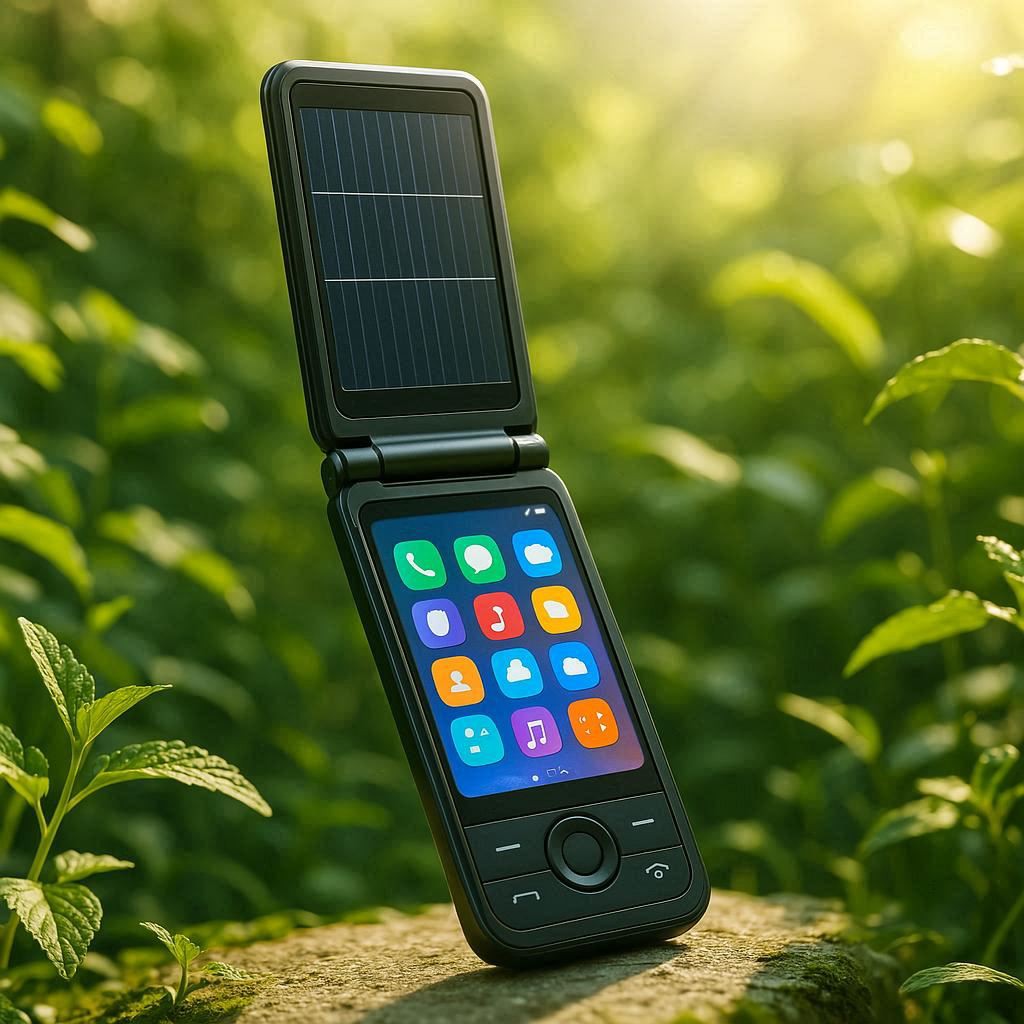
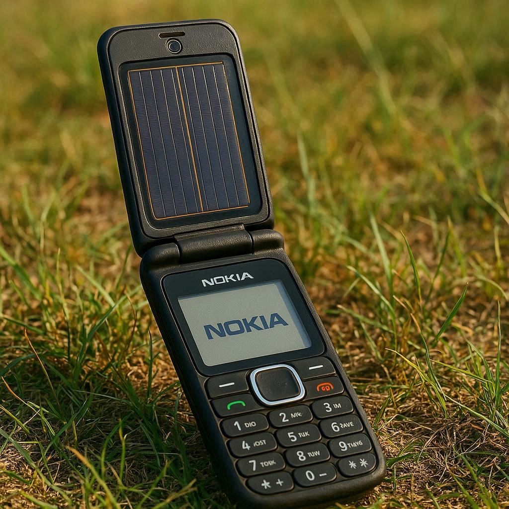
computer rendered concept designs
09/04/2025 at 16:22 • 0 comments![]()
![]()
some new concepts (only the last photo seems practical)
-
06-02-2025 Update
06/02/2025 at 13:08 • 0 commentsVedula has completed synthesis of a ZAP processor (ARMv5T) on an Artix A7!:
Vedula's notes:
"Please see Save/ dir for Synthesis report.
Added a separate Readme for convenience."
syn_timing.rpt
| Design : zap_top
| Device : 7a75t-csg324
| Speed File : -3 PRODUCTION 1.23 2018-06-13
| Design State : SynthesizedXC7A75T-1CSG324C
-
Thought Experiment
09/21/2024 at 19:34 • 0 commentshttps://github.com/hatonthecat/Solar-Kernel?tab=readme-ov-file#copenhagen
The theory, analogy, and metaphor is- solar powered computers are possible, but most have just not realized there was a calculation to be made. (From Copenhagen, 2002, BBC4)
https://youtu.be/RTn9eKfH11M?t=5719 (skip to 1:35:05)![]()
-
Lithium Ion Hybrid Capacitor Circuit & LED Test
08/28/2024 at 14:51 • 0 commentsI successfully tested the Ymin 10mAh, 20 Farad lithium capacitor- it runs continuously and it hasn't been recharged since I received it. Next step is testing a variable resistor, a potentiometer which is pictured in the 1st and 3rd videos to toggle the dimness. I also tested positively a 12V car W5W "dome" LED light that I bought from eBay in 2017 - a 10 pack for $0.99- unsure what kind of voltage it uses (when connected to this breadboard), but similar ones use around 0.2Watts. Green LEDS (not the tinted aspect) use the least power, though using green for everything isn't always preferred.
-
Testing a 20F, 10mAh Lithium Ion Hybrid Capacitor
08/26/2024 at 04:06 • 0 commentsBeing so risk-averse when it comes to testing circuits, electricity is easier written about than tested. That said, I try to make time for actually devising miniscule experiments that test at least one or two things. I am also a very slow learner- I tend to accumulate a ton of idle knowledge and rarely organize the information towards something I actually can see a use for testing (and towards developing a more complex test or build!). The terms "move fast and break things" and "fail fast" doesn't interest me, or at least when it comes to testing circuits, as opposed to carpentry or metalworking (which I never do). Not only that, but "move fast and break things" is counterproductive for circuits at best and dangerous at worst. For this video, I was only able to test one thing- voltage. Granted, I also had an unused multimeter that I only tested once in 2021, and had been wanting to get some use out of it. Not to mention the breadboard and solar power managers that I have laying around in a box. But one step at a time- While the breadboard is pictured, it is not tested in this video. That will come next, once I figure out how to wire the minimum circuit necessary to light the red LED.
A positive result was that the voltage test resulted in a reading of 3.60V, of which the LIC is rated 3.8V. Not sure if that is less than par, or it is just less than 100% charged. Or something like that. The margin of error is somewhere between 0.5-1%, not enough to result in an incorrect reading of 5% margin error:
|Automatic ranging TRMS 6000 count
AC voltage: 6V/60V/600V (±1.2% + 5d), 750V (±1.5% + 5d)
DC voltage 600mV/6V/60V/600V(±0.5% + 5d), 1000V (±1.0% + 5d)
AC current 6mA/60mA (±1.0% + 10d), 600mA (±1.5% + 10d), 20A (±2.5% + 10d)
DC current 60μA/6mA/60mA (±0.8% + 10d), 600mA (±1.2% + 10d), 20A (±2.0% + 10d)
Capacitance: 6nF/60nF/600nF/6μF/60μF/600μF (±3.0% + 5d), 6mF/100mF (±5.0% + 10d)
Resistance: 600Ω(±0.8% + 10d), 6kΩ/60kΩ/600kΩ/6MΩ(±0.8% + 3d), 600MΩ(±1.2% + 10d)
Frequency: 100Hz/1000Hz/10kHz/ 100kHz/1MHz/10MHz (±1.0% + 3d)
Duty ratio: 1%~99% ± (1.0% +2d)
Temperature: -20℃-100℃ -4℉- 1832℉ (± 1.0% + 3)
Diode test, Continuity test, Good Sensitivity of NCV sensor
Full range overloaded protection, Data hold, Live test
Auto Shutdown: 15 minutes
Backlight and flashlight|
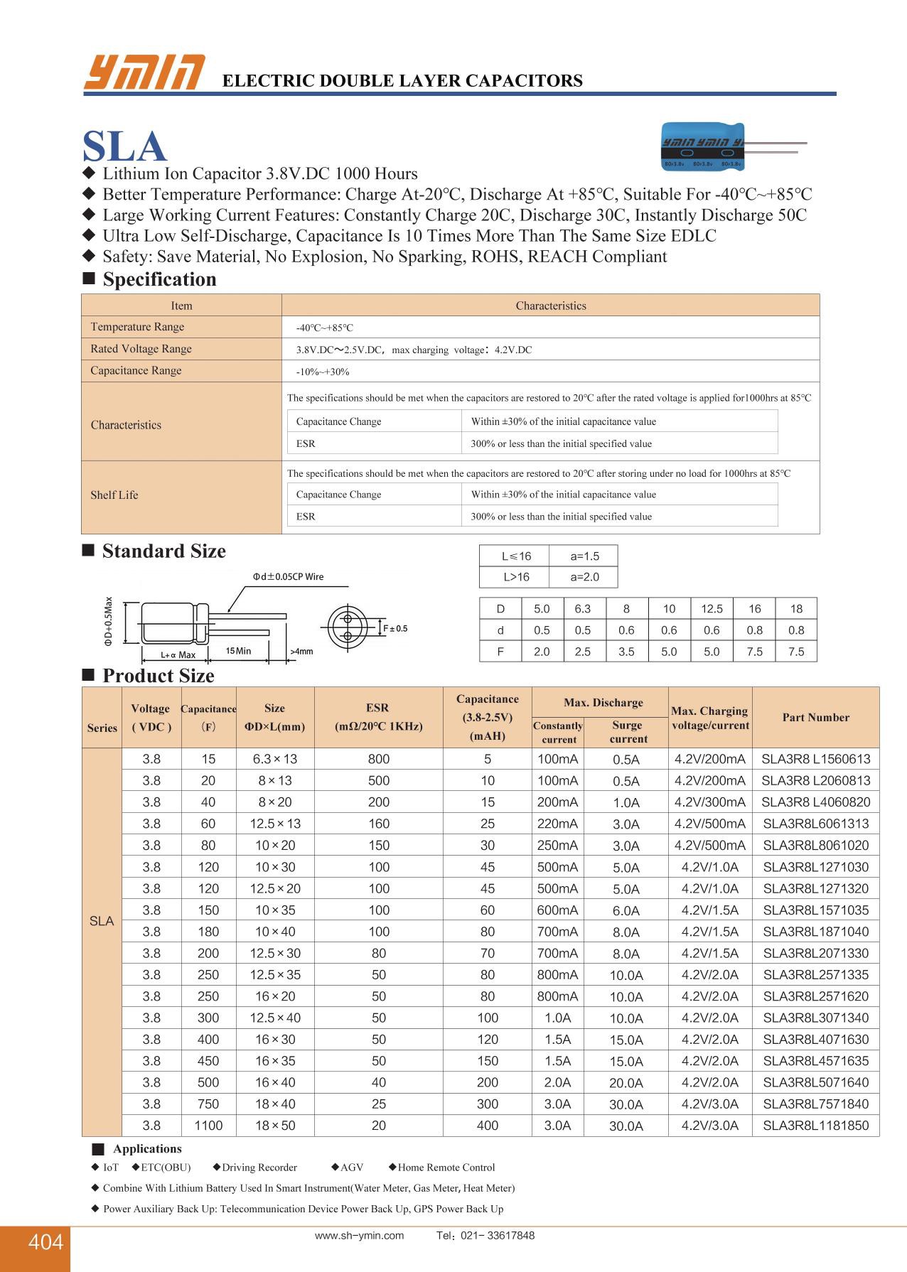
https://www.lcsc.com/product-detail/Lithium-Ion-Capacitors_Ymin-SLA3R8L2060813_C970391.html
Multimeter User UA19B guide: https://drive.google.com/file/d/1uLc5ZH09o1W1XA3oQ490vOcm_m7ylSJ0/view
https://www.amazon.com/gp/product/B08BRG4XN2/ref=ppx_yo_dt_b_search_asin_title?ie=UTF8&psc=1
There are some great tutorials on breadboards:
If I haven't posted a project log in a while, it's probably because I'd like to have something more substantial to showcase in a video than a single test. But I'm ok with that too.
Note: the 9V multimeter battery is being replaced very soon! It will be interesting to discover whether the low battery level was causing a 5-6% measurement error rate, which would suggest it is actually 3.8V...
----
An English version of the data sheet can be viewed here:
https://en.sekorm.com/doc/2768518.html
![]()
"The SLA3R8L2060813 from Shanghai Yongming Electronic is a Supercapacitor with Capacitance 20000 mF, Voltage Rating 3.8 V, Equivalent Series Resistance 500 mOhms, Temperature Operating Range -40 to 85 Degree C. Tags: Through Hole. More details for SLA3R8L2060813 can be seen below.
Product Specifications
Product Details
- Part Number SLA3R8L2060813
- Manufacturer Shanghai Yongming Electronic
- Description 20000 mF, 3.8 V, 500 mOhms, Electric Double Layer Supercapacitor
General
- Types of Capacitor Electric Double Layer Supercapacitor
- Capacitance 20000 mF
- Voltage Rating 3.8 V
- Equivalent Series Resistance 500 mOhms
- RoHS Compliant Yes
- Temperature Operating Range -40 to 85 Degree C
- Dimension 8 x 13 mm
- Package Type Through Hole"
----
A 10mAh supercapacitor/hybrid capacitor would allow up to 10 hours of charge for a 1 milliamp hour Ambiq Apollo3 microcontroller! https://www.sparkfun.com/products/15444
-
Steve Jobs' 1984 Macintosh, & Why Designing a Solar Powered Laptop integrates New Tech the same way.
10/02/2023 at 19:54 • 0 comments -
Review of project status (and some history of telecommunications)
10/01/2023 at 02:48 • 0 comments -
Adapted Pi-Top for solar panel by replacing display cable outlet for DC cable
03/20/2021 at 13:17 • 0 commentsWas able to fit a 5" screen in Pi-Top v3, thus considering use as a cyberdeck instead of main panel.
-
Solar powering Ambiq Micro Apollo3
03/17/2021 at 16:14 • 0 comments -
Powering the 5mW Artemis Nano fully on a 10.5 Phillips LED
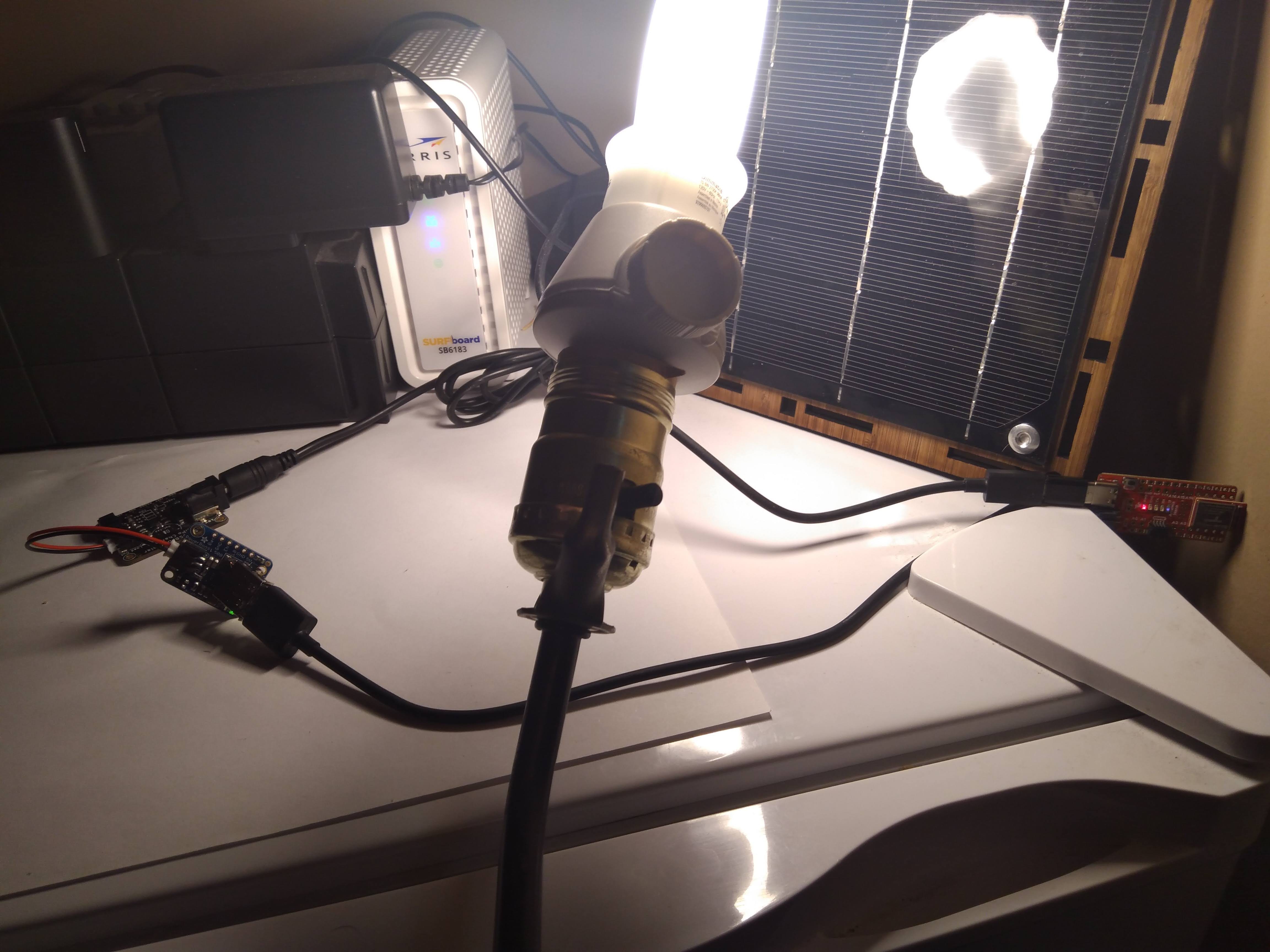
03/09/2021 at 05:04 • 0 commentsGot my Artemis Nano to power on completely with a 10.5W LED, far less than the 45W Cowboy Studio CFL I was using with the 2V, 160mAh panel in my previous log . Since the bluetooth LED is is blinking, it must be using around 5mW, which is probably not very efficient, although it is the only way I can connect [using an Adafruit Universal USB / DC / Solar Lithium Ion/Polymer charger w/ TI BQ24074) the 5W panel to the USB-C input of the Artemis Nano at the moment. Some efficiency loss is likely, since it travels through the 500mA boost converter.
![]()
Later I put the lampshade back on the Philips and was able to get a red LEDd, but it took a while for current to flow through the entire circuit. With some efficiency improvements (i.e soldering the 500mV boost and panel placement), it is very likely that the Artemis Nano can be powered in a more ambient condition (i.e not a bulb directly on the panel as in the above photo.)
I’ll also try my Powerfilm Dev-in-Basic w/ BQ25570 development kit sometime.
The FemtoTX Motherboard Standard
A solar-powered, Raspberry Pi-like Board idea that runs on 5mW