Overall concept:
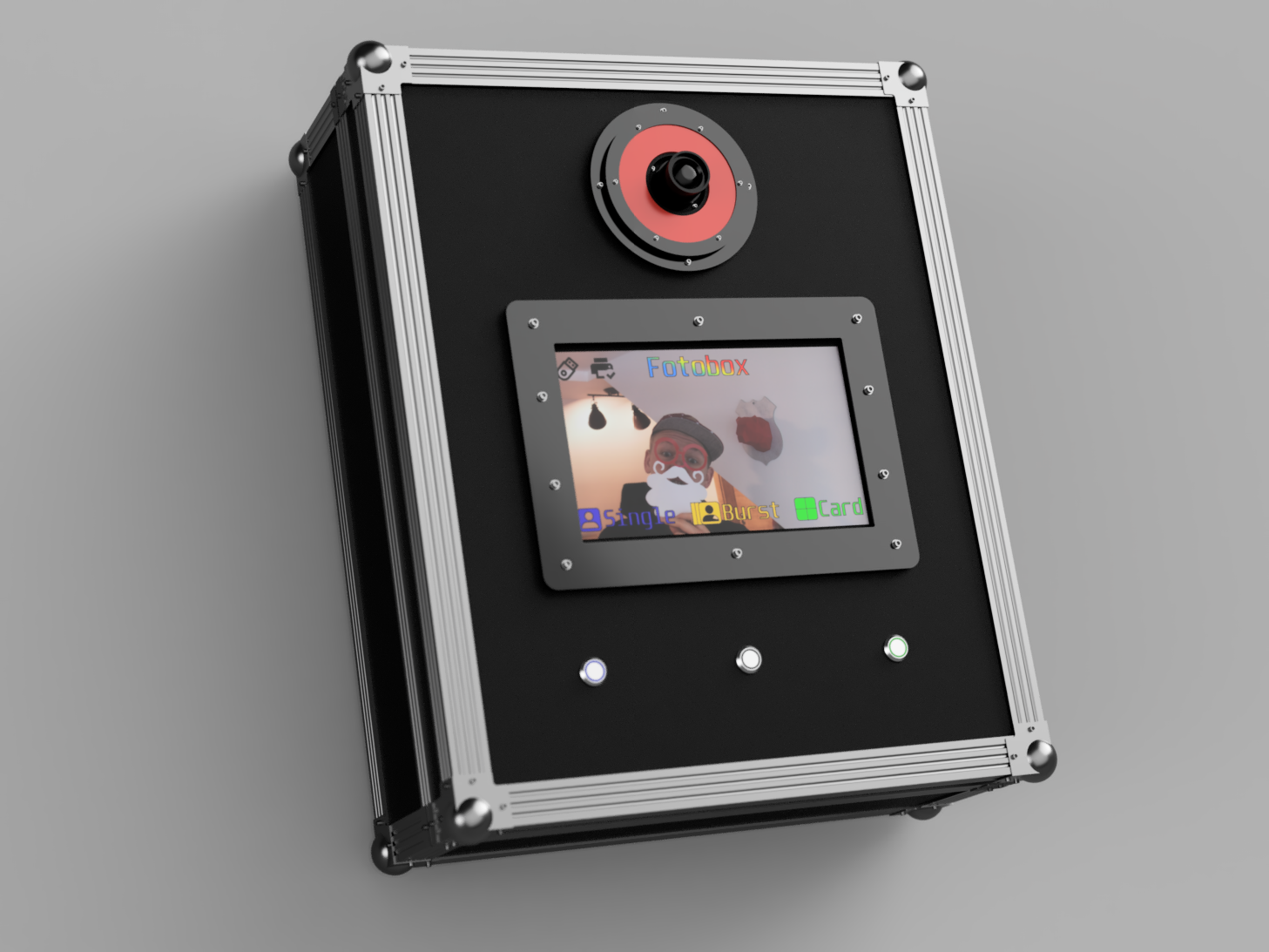
The main idea and starting point of our project, was to develop an easy to use and cool looking photobooth, which we could use on our private parties. Because we did`t want to overdraw our budget, we decided to use the afordable raspberry pi camera. In our first photobooth we even used the second version, which has lower qualitiy than the HQ cam. But even with this camera the results are pretty amazing. To ensure a long life for our photobooth, it was clear, that we need a proper housing. The ideal case for such a project are Roadinger-Boxes, which can be bought and found on eBay very quickly. This makes it not only a very durable photobooth but also very easy to transport! The main interaction is handled over a touch display and three physical buttons in the front of the roadinger case. We included the buttons mainly because we wanted to prevent sticky fingers from touching the display and you know drunken people are best in getting sticky fingers! To keep the party in memory you can instantly print out your photo and take it home with you. For this we connected an photoprinter via USB. Sadly the handling and the size of the printer doesn`t allow to integrate it into the case rightnow, but we plan to add this feature!
Main PCB:
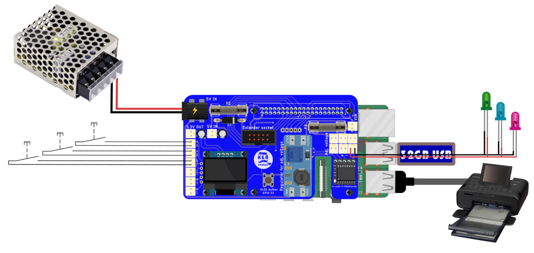
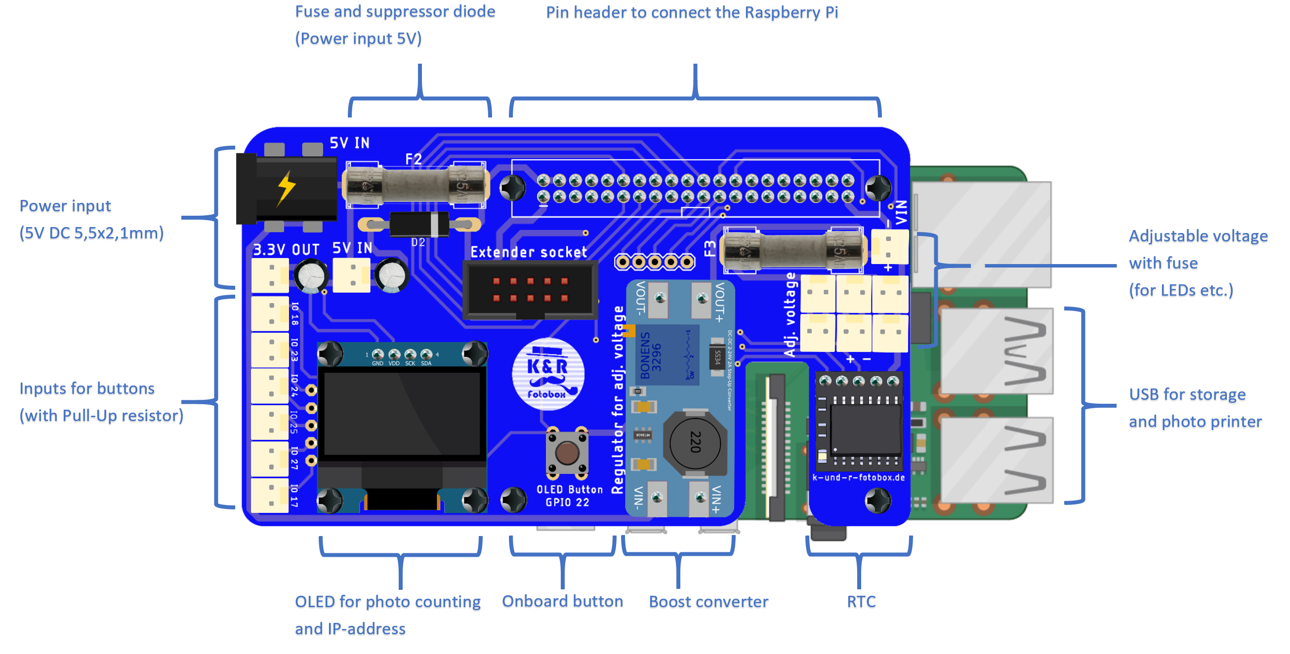
One keyfeature of our photobooth is the main pcb, which contains allmost all necessary components for a proper working system. The board is powerd with 5V over a DC-connector (5.5x2.1mm). To protect all components, the 5V line is secured by a glass fuse and a supressor diode, which prevents shortcuts, overvoltage and reverse polarity. This is especially important because the PI is also powered by this and we don`t want to kill the PI by a voltage spike or something else. We also included a step-up converter to have a comfortable way to power LEDs which are often included in buttons. To check the number of printed photos in the field, there is an OLED connected over I2C with the PI. The IP-address is also shown on this display. Buttons and other inputs can be connected over JST-connectors on the left. The used GPIOs are pulled up by a 10k resistor. There is also a onboard button to trigger actions like resetting the photo counter. All GPIOs, the 5V line and the adjustable line are combined in the extender socket, which can be used do add an other board. This is a quite convenient way of organizing the cables for buttons and LEDs. To keep the time of the PI up to date, there is also a RTC included. This makes it really easy to differentiate the photos of various events faster.
Circuit overview:
The overall circuit of our system is pretty simple. Keep in mind that building this project includes connecting a power supply with mains voltage. If you are not experienced in working with AC voltage, instruct an technician. 
 Printed and lasercutted parts:
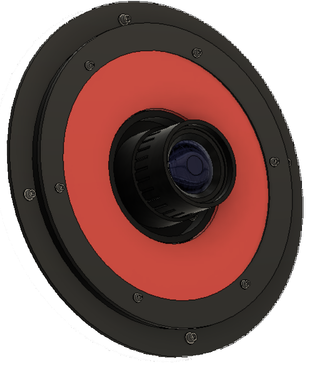
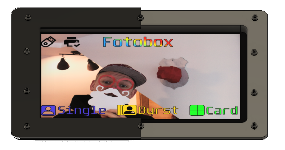
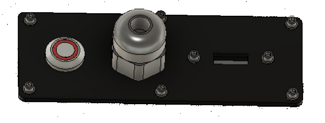
Most functional or optical parts, apart from the case itself or the connector for the box holder, are 3D-printed or cut out from acrlic sheets by the lasercutter. The printed parts are mostly not vissble, because they are hidden behind acrylic parts, this makes the surface of the photobooth look much better and smoother.
 Kirschner Christoph
 Arnov Sharma
 CompuCat
 Cees Meijer
 DeiGray