-
Printing a lens rim
06/22/2021 at 07:59 • 0 commentsEach Lubitel camera has its own charm! For this project it translates to the need of matching a lens rim to the camera body. From my experience, it can be done just by measuring the body (the diameter of the inner screw thread). Essentially, you need to print and match until the proper rim size is found. To simplify the process, I prepared a set of STL files with rims of different sizes. The files are named according to the following convention:
- the first number marks the outer screw thread clearance: the higher the value, the looser the rim-to-body engagement. I suggest starting with the clearance of 25 (0.25mm), then print the rim and test it against your camera body. If the engagement is too loose, switch to a lower clearance value (i.e., 20 == 0.20mm) and repeat printing. If the engagement is too tight, then switch to a higher clearance value (i.e. 30 = 0.30mm) and repeat printing. The best result is when the rim turns smoothly without applying excessive force.
- the second number marks the inner screw thread tightness: the higher the value, the tighter the rim-to-lens engagement. The default value of 10 (0.10mm) worked well for of the lenses I worked on. The main thing to avoid here is a loose engagement, because it results in the lens not being coaxial with the rim. Please report your case if 0.10mm tightness doesn't work for your lens.
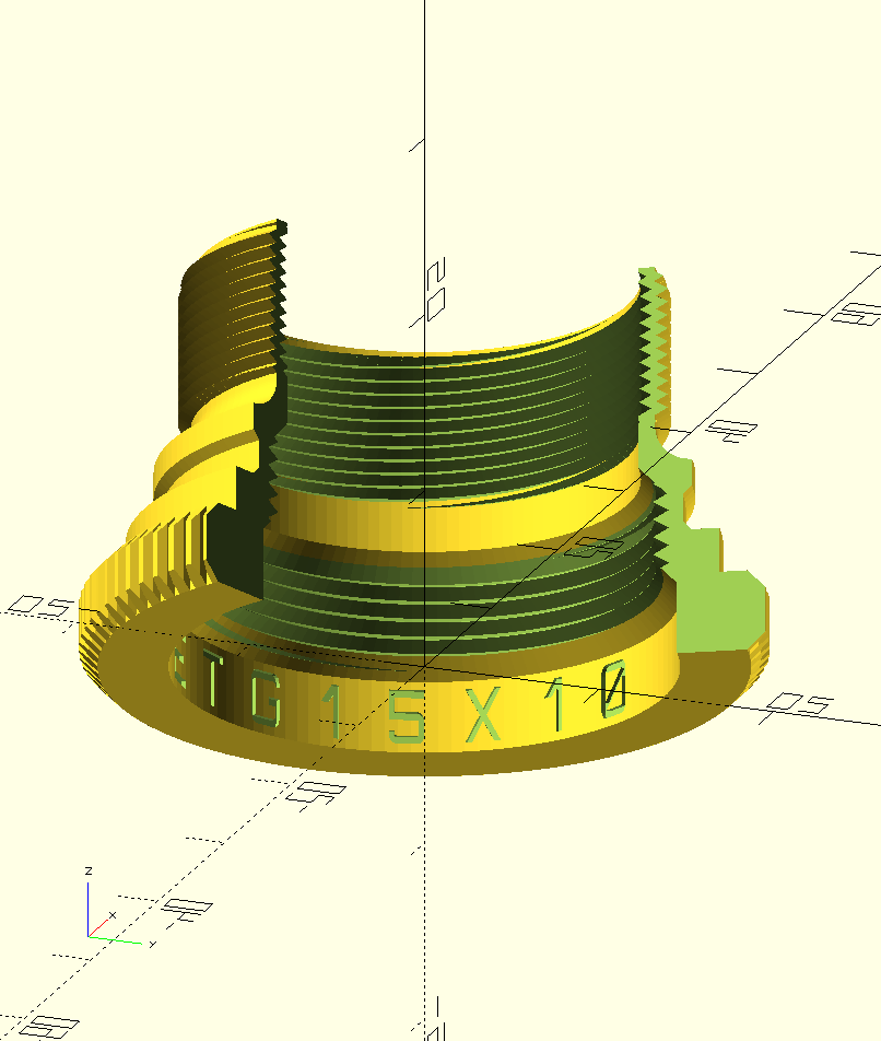
- All the models in the STL files bear the same marking (clearance x tightness) on the inner surface of each rim - it should help not to confuse the prints.
The lens rim 3D model is designed for the following printing settings:
- 0.45mm nozzle
- 0.20mm layer height
- PETG filament
- single perimeter
- 3 top/bottom layers
- 5-10% infill
Please, before printing, pay special attention to first layer calibration. "Elephant foot" would ruin the printed lens rim for sure because the rim's teeth would not mesh properly with a Lubitel's lens rim.
-
Selecting a 3D printer
05/14/2021 at 07:30 • 0 commentsSince the project is about making a functional part for a Lubitel camera, a rather precise device, and a 3D printer is the final step of manufacture, the printer should be capable of delivering enough precision.
I developed the 3D model without any special requirements for the printer in mind. Also, taking into account the choice of filament, which has no issue with adhesion, I assume that any conventional 3D printer should work. Direct drive extruders are preferred though - I chose Prusa.
-
Selecting filament
05/14/2021 at 07:22 • 0 commentsIn this project, PLA filament was good enough for the proof-of-concept prints. Once I was confident in the overall approach, I switched to PETG which is heat- and oil-resistant. Oil resistance is important because the camera lens screw thread should be lubricated with grease.
As in my other Lubitel project, I chose recycled filament: r-PLA and r-PETG by EKO MB. And I'm more than satisfied with the results!
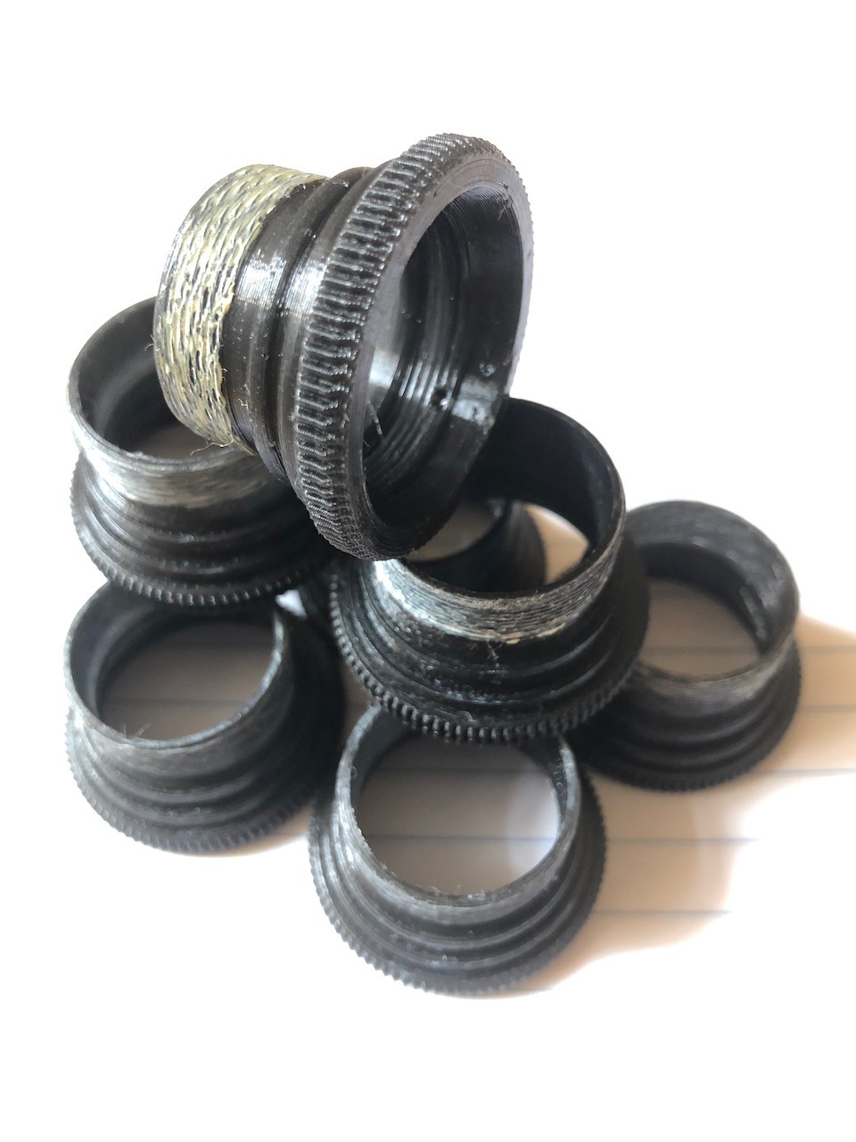
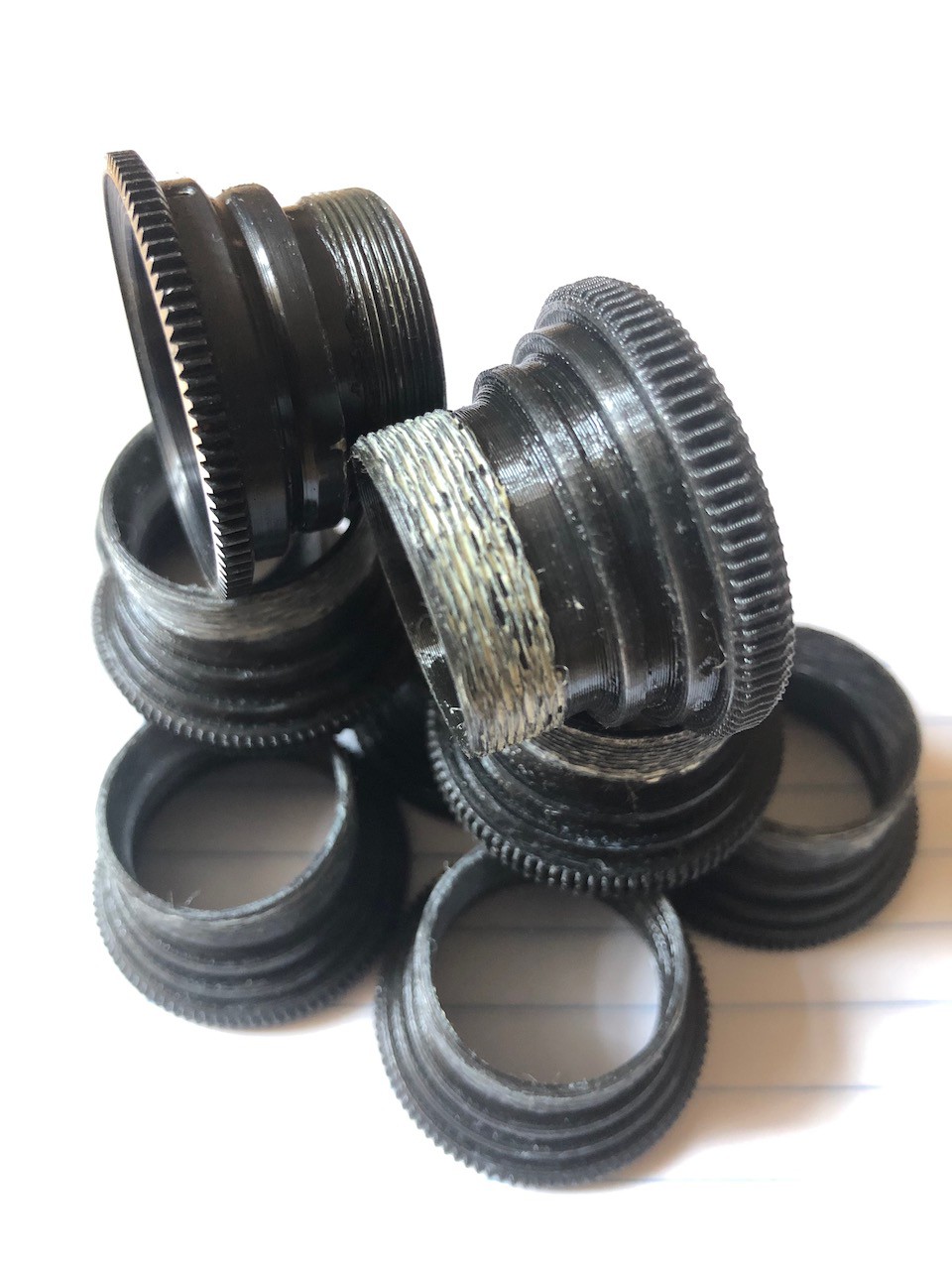
![A set of replacement lens rims printed with PETG A set of replacement lens rims printed with PETG]()
A set of replacement lens rims printed with PETG -
Releasing the 3D model
03/13/2021 at 22:22 • 0 commentsOnce I identified the reason for the enormous backlash and came up with a method that would resolve the issue, I reverse engineered the design of the original lens rim. Then I created a 3D model with OpenSCAD and printed the first PoC. This first prototype of the replacement lens rim showed that a conventional 3D printer (0.45 mm nozzle, 0.20 mm layer) gives the level of precision comparable to the original aluminum rim.
![A reverse engineered rim compared to original one (on the left) A reverse engineered rim compared to original one (on the left)]()
A reverse engineered rim compared to original one (on the left) Inspired with the first results, I started adjusting the 3D model. It took me more than twenty intermediate prints to finalise the design. Here are the main improvements: a longer screw thread compared to aluminum rims; chamfers interspersed here and there to increase strength; a printing-friendly approach (less plastic, faster printing).
![A replacement rim for Lubitel viewing lens A replacement rim for Lubitel viewing lens]()
Cross section of the 3D model While printing replacement rims and attaching them to each of the available Lubitel cameras, I learned that each camera requires a specific replacement rim that matches the camera. Moreover, the 3D printer and filament being used do affect matching. For that reason, I generated five slightly different STL files. I labeled each file with two numbers. The first one denotes the rated backlash value of the outer screw thread: 0.10 mm, 0.15 mm, 0.20 mm, 0.25 mm, 0.30 mm. The second number denotes the rated tightness of inner screw thread (the thread for the lens itself). It seems, that 0.10 tightness works well in most cases (though this is not the case with the outer thread). My recommendation is to start with the 0.20 mm STL file to see how the printed replacement rim fits into the camera body. If it is too tight, then try the 0.25 mm STL. If it is too loose, then try the 0.15 mm STL. If after the first iteration the rim doesn't fit well, go to the 0.30 mm STL and 0.10 mm respectively.
-
What is wrong with Lubitel cameras?
03/09/2021 at 13:59 • 0 commentsAs I mentioned earlier, there is an issue with most of the Lubitel cameras that I handled. According to my own experience, all of the models (i.e., Lubitel, Lubitel-2, Lubitel-166) are affected. The issue lies in the viewing lens (the top one) and manifests itself in enormous backlash of the screw thread. Basically, the lens jumps back and forth and from side to side instead of smooth turning and sliding. This makes focusing practically useless –you never know on what point you've actually focused the camera.
Having observed this problem consistently with cameras of different ages and conditions, I concluded that the reason is not in the design of camera, nor is it due to abusive handling. I stuck with my little "investigation" until I noticed one significant detail: the top lens has a rim made of aluminum, which turns in a brass nut molded into the Bakelite of the camera body. As far as I know, brass is a very stable material and doesn't change properties over time. Aluminum, by contrast, is affected by ageing. Without alloying additives or applying special treatments, things made of aluminum shrink over time. Taking into account that most existing Lubitel cameras were made during the Soviet Era, they are pretty old now and have had enough time for this kind of metal degradation to develop. How much can they shrink over time? I don't know exactly, but my later experiments showed that 0.05 mm reduction in the outer diameter of the lens screw thread is enough to create enormous backlash.
How to solve the issue? I know for sure that aluminum products can be stretched a bit, but the procedure requires industrial equipment. I decided to leverage 3D printing, and I set a goal of developing a replacement lens rim that can be printed with a conventional printer.
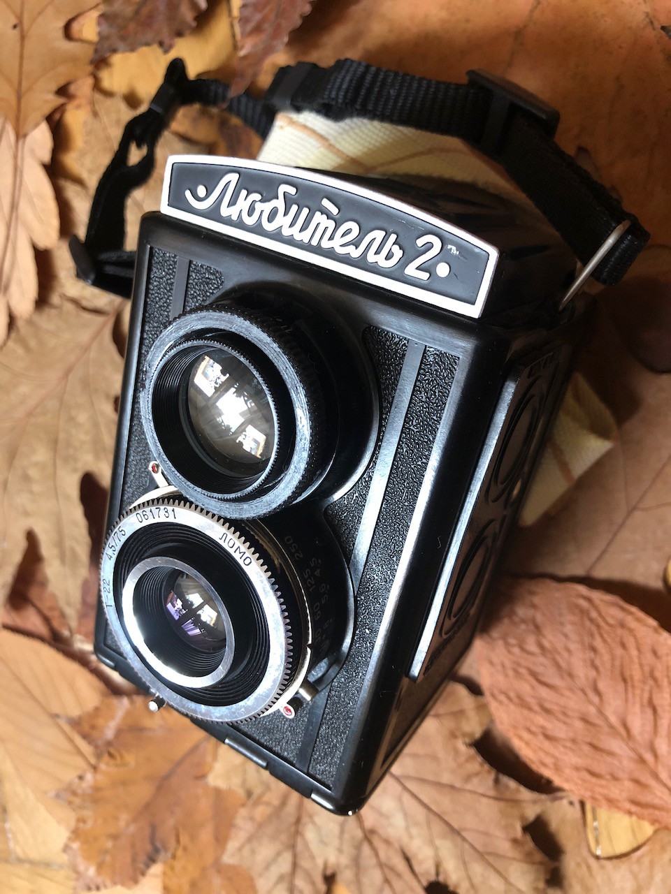
![A Lubitel-2 camera with a 3D printed replacement lens rim fitted A Lubitel-2 camera with a 3D printed replacement lens rim fitted]()
A Lubitel-2 camera with a 3D printed replacement lens rim fitted -
Why I started this project
03/08/2021 at 06:47 • 0 commentsWhile I was working on L2Camera — a project related to Lubitel cameras — I learned the following three things.
Firstly, these cameras are simple and therefore reliable, repairable, maintainable, and they are equipped with decent glass lenses.
Secondly, they are available in abundance - several million of these cameras are spread around the world, mostly in Eastern Europe. My experience shows that you can find a good used Lubitel camera for $10. Compared to the newly produced Lubitel 166+ model sold by the Lomography society for almost $400, ten dollars is nothing. I have had no hands-on experience with the 166+ model, but I believe it is nearly identical to its ancestors.
Thirdly, out of perhaps a dozen that I went through my hands, only one Lubitel camera was capable of producing good photos. Maintenance procedures like cleaning, oiling, and lens aligning didn't help. It took me rather a long time to figure out the reason and come up with a solution.
For those who want to have a fully functional Lubitel camera, this project describes the inherent problems with Lubitel cameras, and offers some practical solutions.
I will describe the technical issues in more detail, and then move on to share my solutions.


