-
1Purchase and strip the Supermicro Power Distribution Board (PDB)
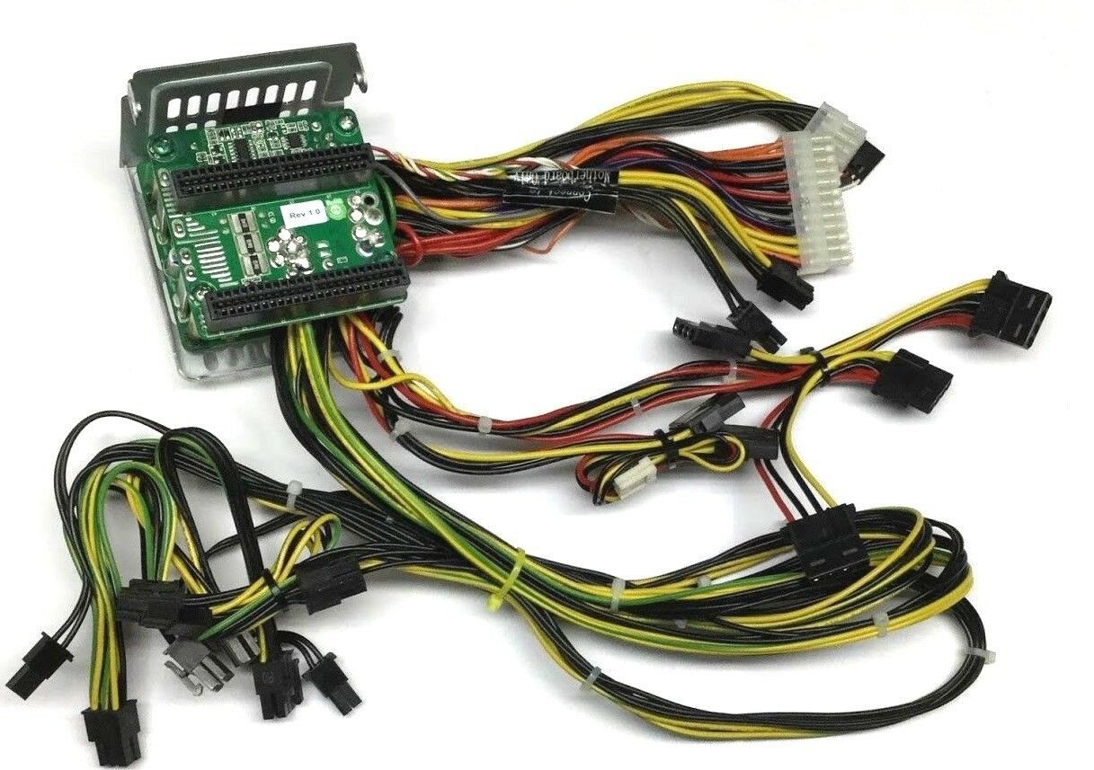
Go out to eBay and find this PDB: Supermicro PDB-PT825-36824 SC825. It features three GPU power cables. Each GPU cable has a one 8-pin and one 6+2 pin connector.
![]()
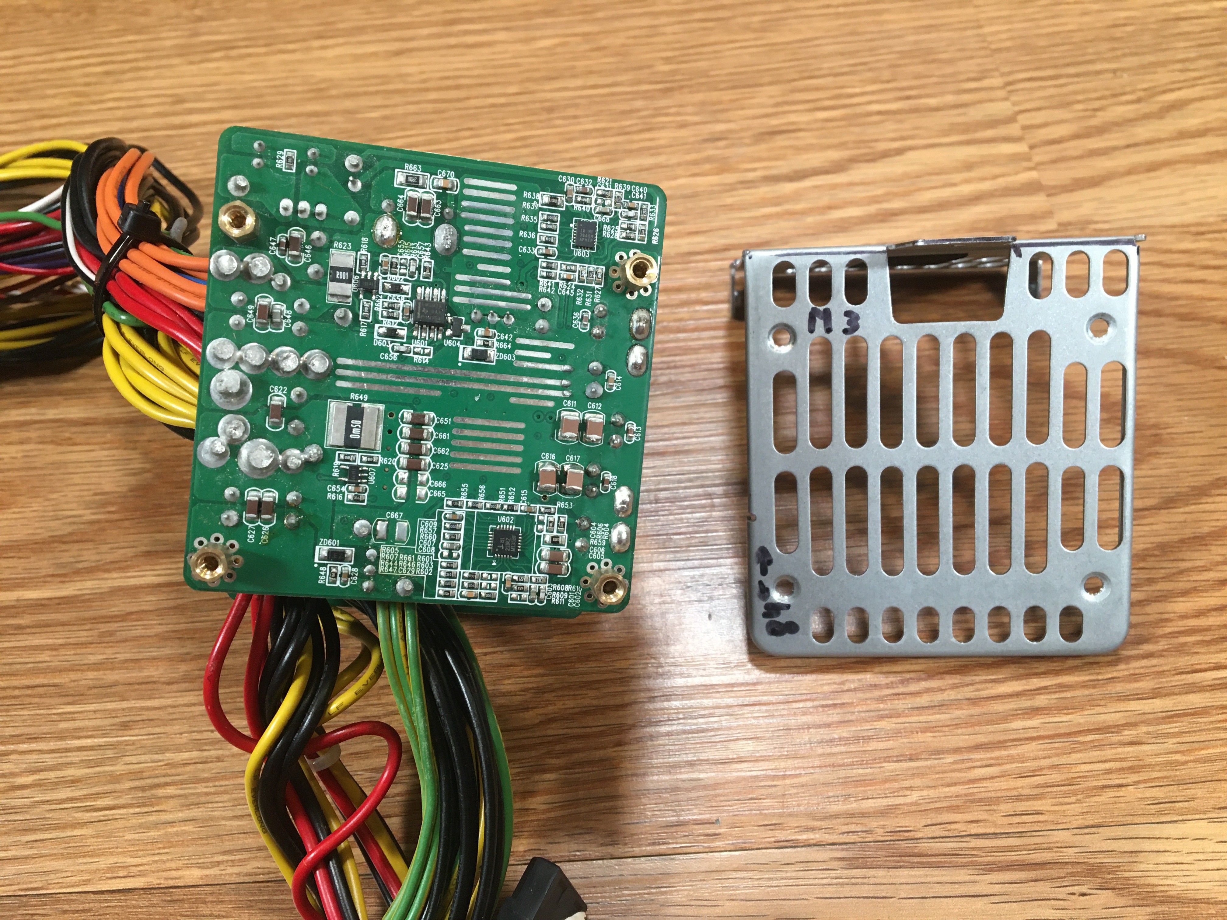
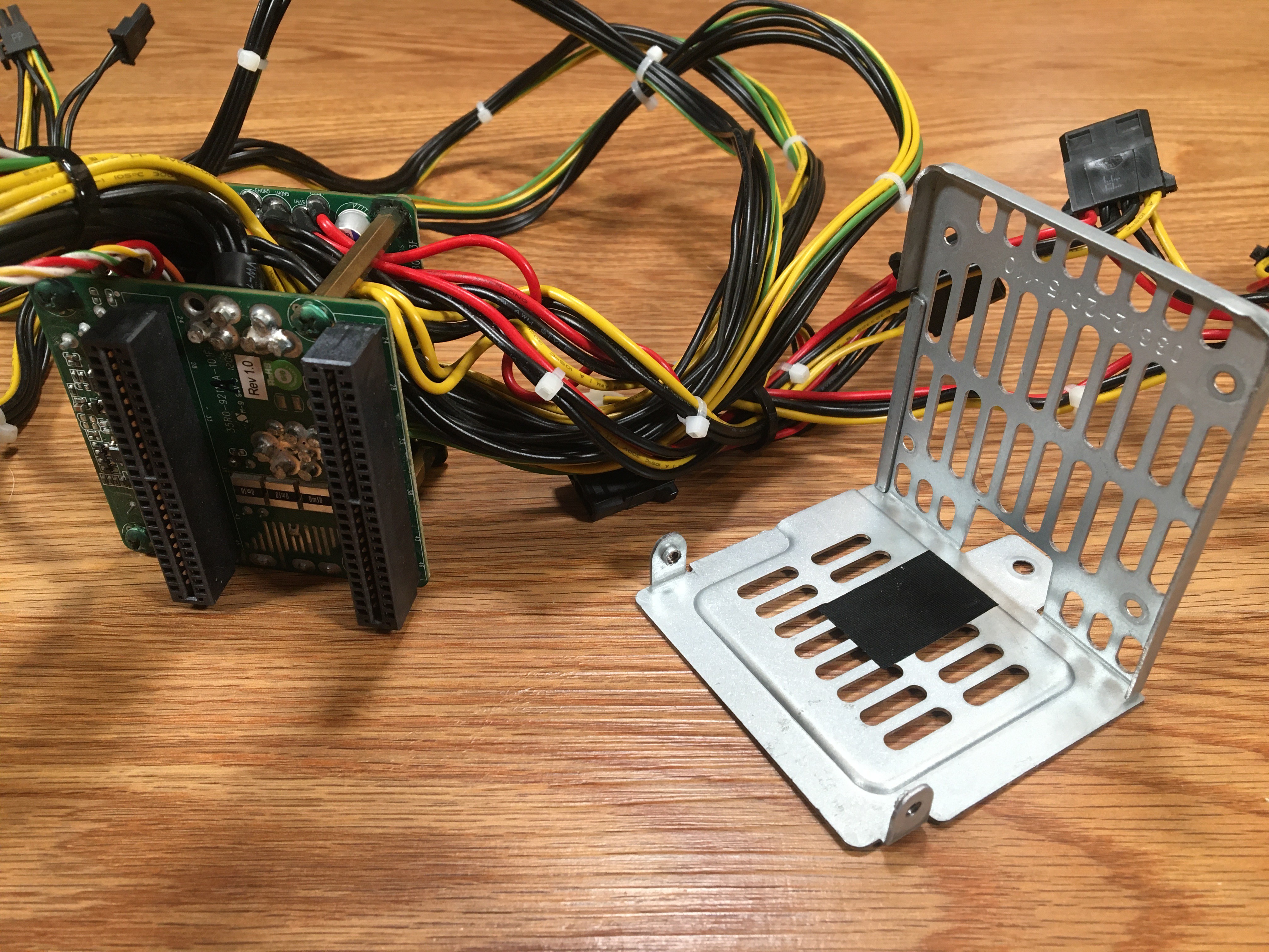
After this PDB arrives, strip off the metal plate. You won't need it.
-
2Purchase two Supermicro power supplies
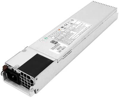
The Supermicro PDB-PT825-36824 is a "23-pin" model and will accept both the 23-pin supplies and the 19-pin supplies. This is not an exhaustive list, but just the various models that I had sitting at home that I know fit into the PDB-PT825-36824.
23-Pin Model Numbers
- PWS-1K28P-SQ | Quiet, 1000W at 120V, 80 Plus Platinum
- PWS-920P-SQ | Quiet, 920W, 80 Plus Platinum
- PWS-1K41P-1R | Loud, 1100W at 120V, 80 Plus Gold
19-Pin Model Numbers
- PWS-1K21P-1R | Loud, 1000W at 120V, 80 Plus Gold
If you choose to find a model that is not listed above, you should start by looking at the Supermicro Power Supply Matrix. The only supplies that will physically fit have these dimensions:
- Length (mm) = 336
- Width (mm) = 76
- Height (mm) = 40
Unfortunately, the matrix doesn't tell you which supply is 19-pin and which is 23-pin. However, if you do a Google search like this:
"PWS-1K28P-SQ" site:supermicro.com
Then you will get as your top hit this link: https://store.supermicro.com/1280w-1u-pws-1k28p-sq.html
Scroll down to the 'Detailed Specification' tab, then look for "Output Type Gold Finger (23 Pair Connector)".
I am using two PWS-1K28P-SQ supplies:
![]()
-
3Purchase an ATX power cable extension kit
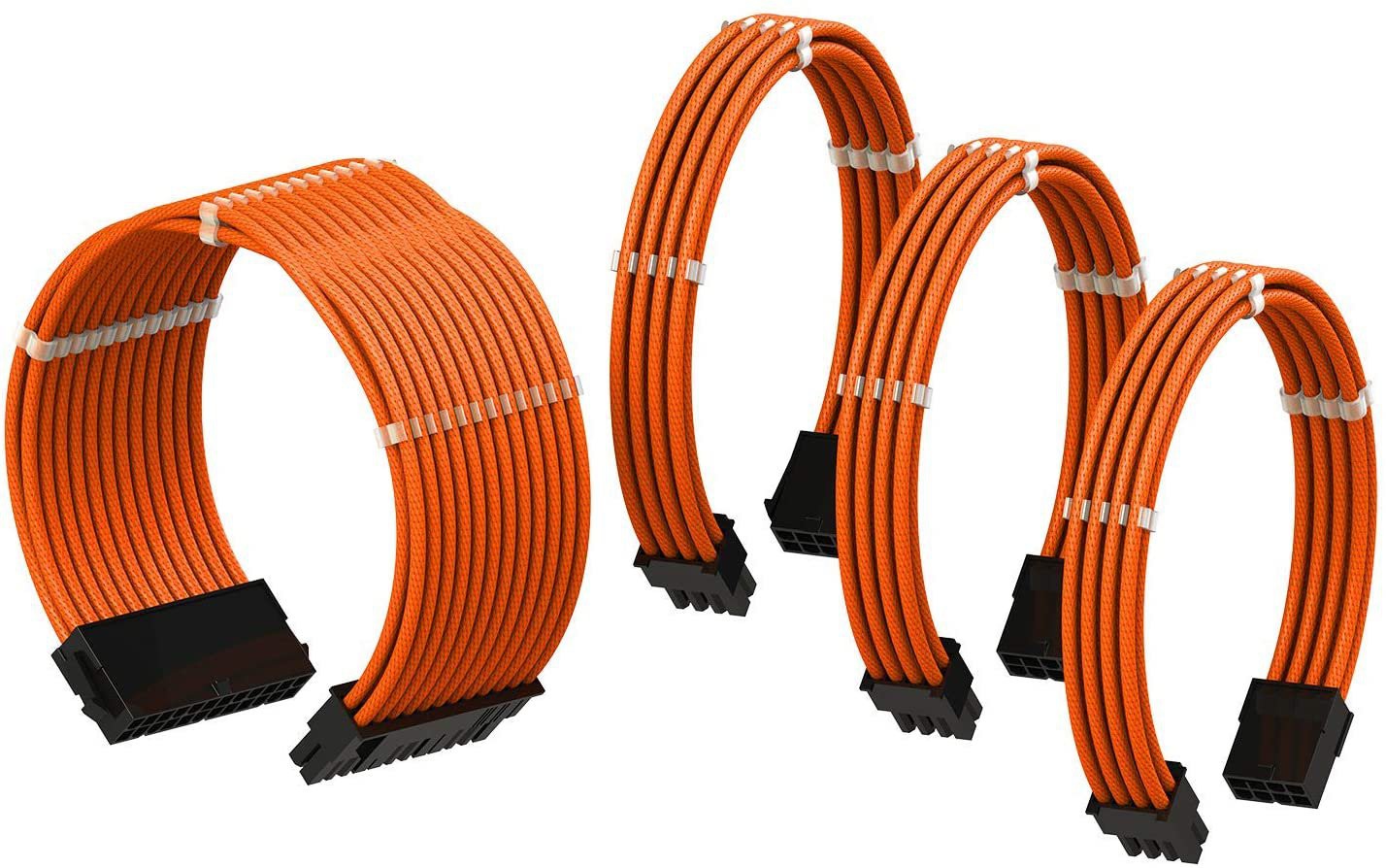
If you look at Step #1, you will notice how the 24-pin and dual EPS12V cables are extremely short. If your motherboard has its 24-pin connector at the top of the board, you will need a 50 cm extension. If your motherboard has its 24-pin connector on the side, a 30 cm cable will work.
I purchased a 50 cm extension kit because my ASUS Pro WS x570-ACE motherboard has a single EPS12v connector on top.
My cable extension kit: Amazon - LINKUP
![]()
-
4Buy a 40mm fan
The standard 2U Supermicro server case has rather good airflow, which keeps everything chill. Because we have stripped all that away, there is no telling if the PDB will receive enough airflow to stay cool. To address this potential issue, I chose to include a 40mm fan, blowing across between the PDB layers. When you order a fan, make sure it has a 3 or 4-pin rectangular connector, so it plays well with standard ATX motherboard fan headers. I highly recommend you use a top quality fan because if this fan goes bad, you have to do a lot of work to replace it.
You really can't go wrong with this: Noctua NF-A4x10 FLX, Premium Quiet Fan, 3-Pin (40x10mm, Brown)
![]()
-
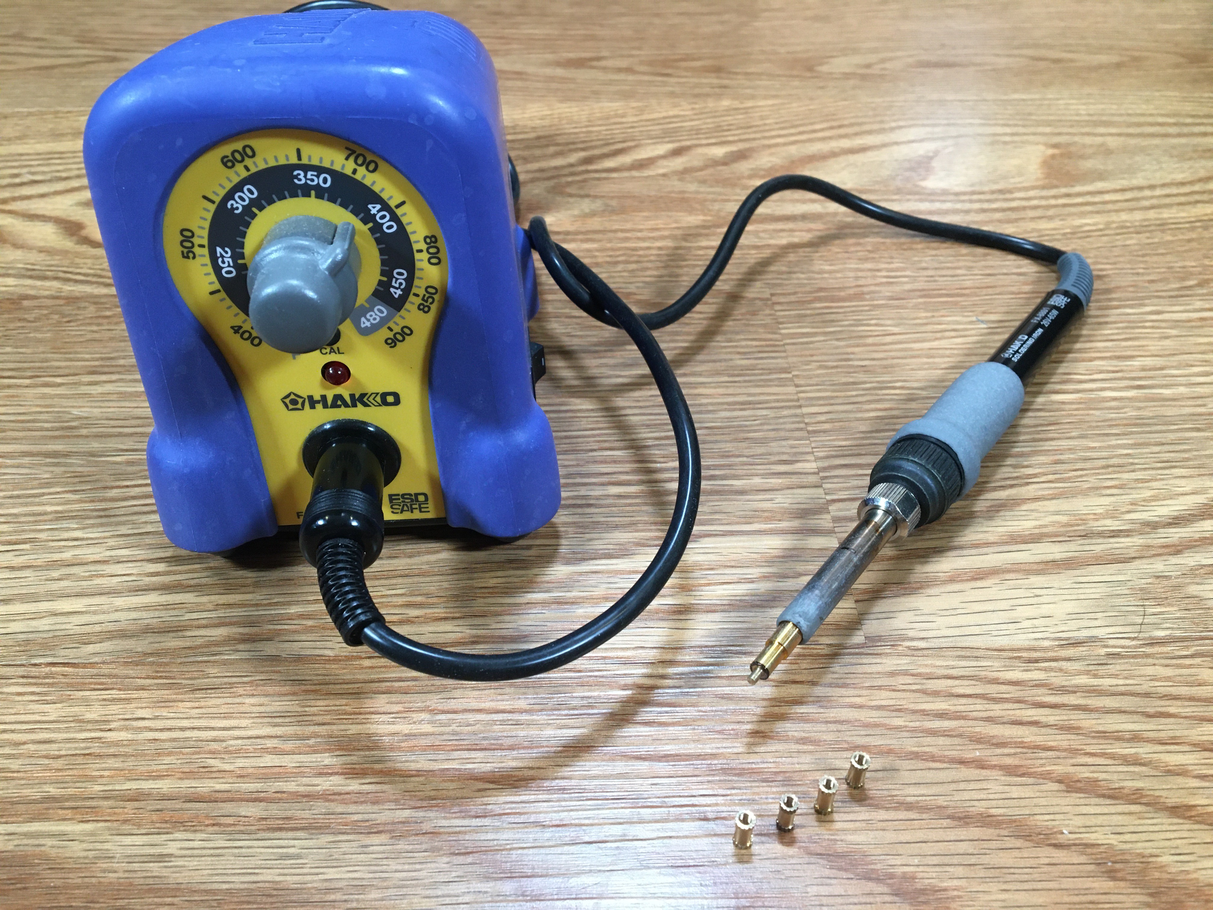
5Beg, borrow, or buy a soldering iron
The soldering iron is used to heat the brass knurled inserts into the printed model. My iron is a Hakko FX-888. Total power is 70W, and works great for heating the brass inserts when set to 730 F / 390 C.
-
6Buy a heat-set insert installation tip
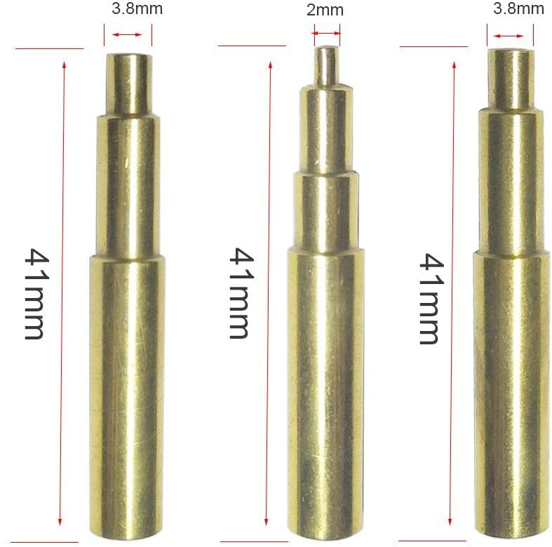
A standard soldering iron tip isn't made to press a brass insert down into a 3D model. Therefore, I recommend a set of these heat-set inserts:
Heat-Set Insert Installation tip for Hakko FX-888D #4-40, M2, M2.5, M3, M4, and M5 Inserts
![]()
-
7Buy brass insert nuts
These bad boys have so many different names that a single eBay/Amazon search won't find all the sales. Here is a list of adjectives that you should use when searching.
- Knurled
- Insert Nuts
- Blind
- Blind Hole
- Single Pass Through
- Brass
- Injection Molding
- Threaded
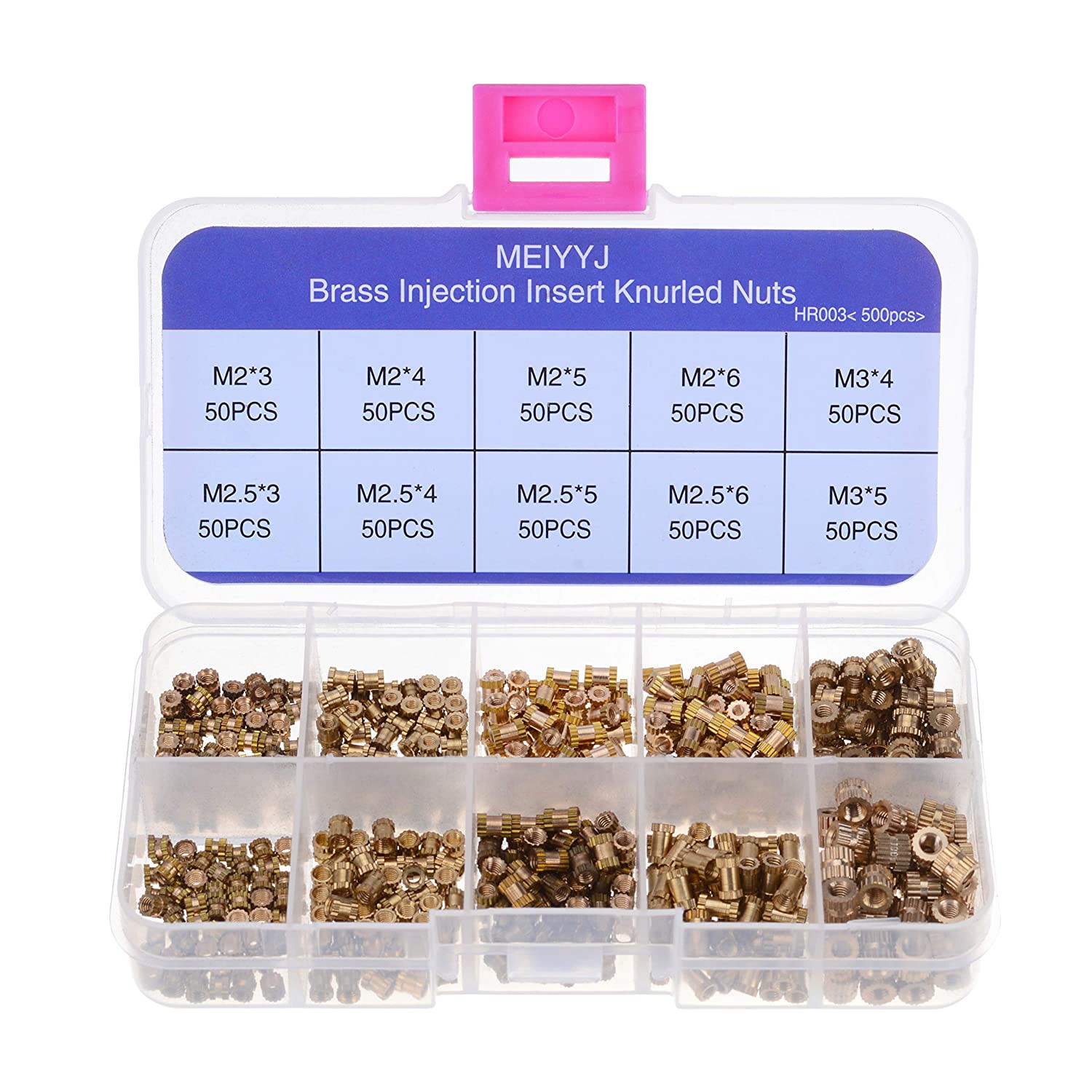
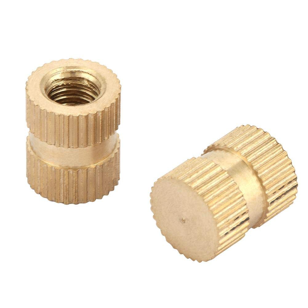
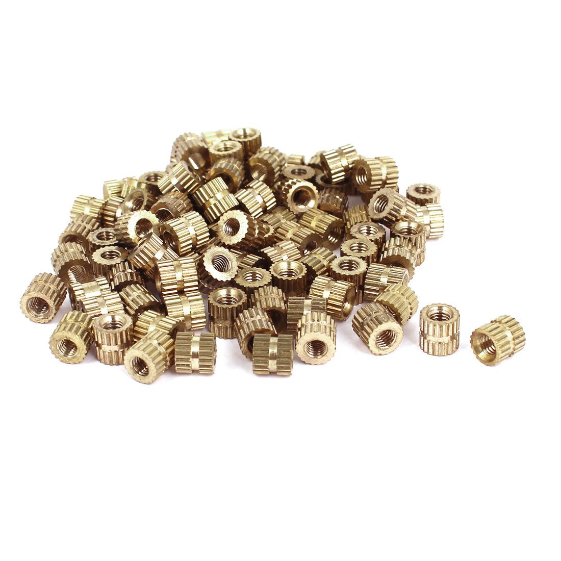
Here are some photos of what you are looking for:
![]()
![]()
![]()
I highly recommend that you look for the inserts that are labeled "blind". These nuts are closed at one end; see the middle photo above. I believe the blind nuts are superior to the open-ended nuts because when you press a hot brass nut down into the filament, it melts and scrapes the walls. This melted filament has the potential to build up at the bottom of the nut and ooze its way up into the threaded area. Effectively, this can reduce the total length of internal threads that a screw/bolt can grab on to. Blind nuts do not suffer from this problem. Unfortunately, M2.5 blind nuts can be difficult to find.
This is the
droidsize you are looking for: -
8Buy bolts, washers, and nuts
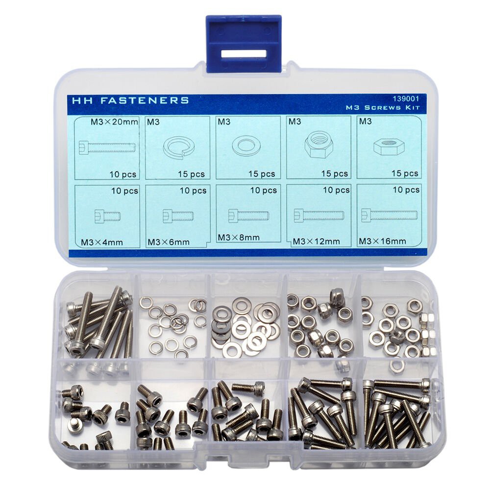
This is a long list, with some very small counts. You might be able to find some of the M2.5 and M3 bolts as a combination pack.
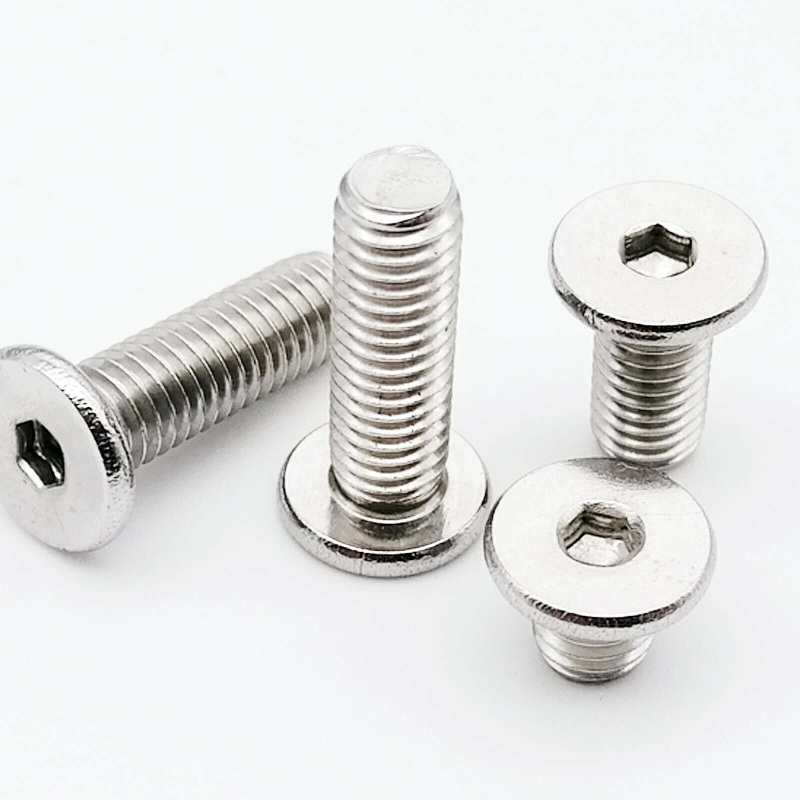
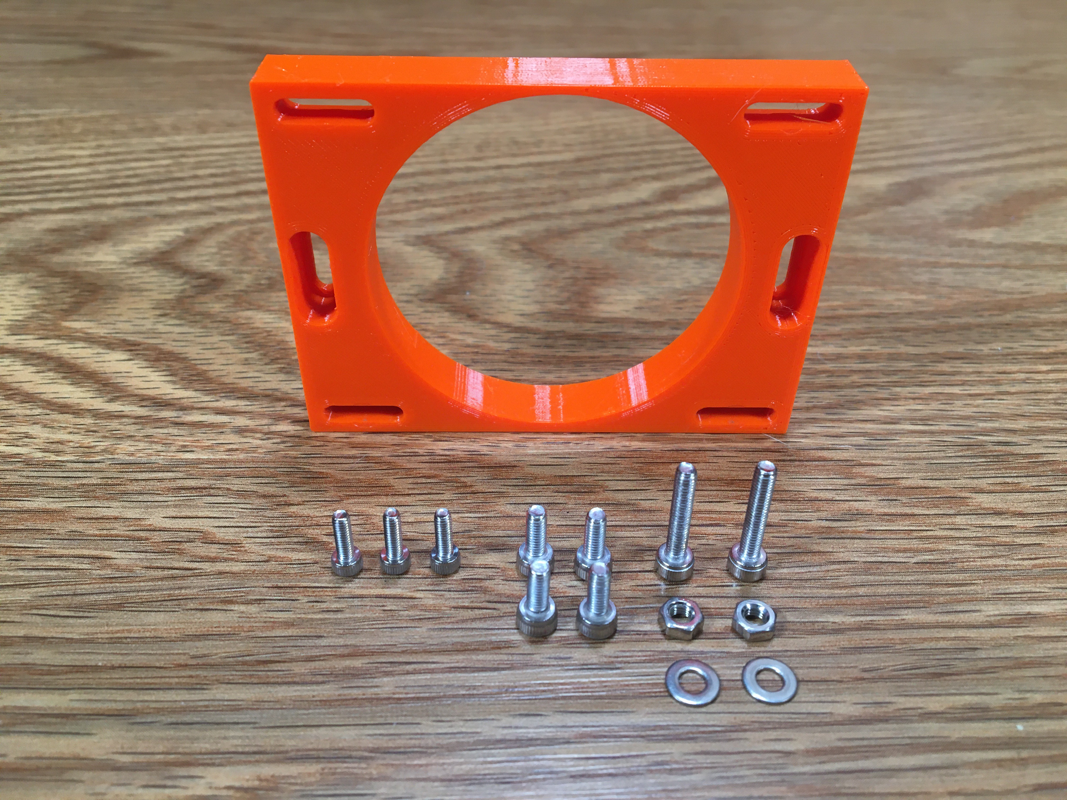
Diameter Length Type Count Purpose Link M2.5 6mm Hex Socket Cap Bolt Seven Joins the three ATX Adapter pieces together Link M3 8mm Hex Socket Cap Bolt Four Joins the PDB to the PDB mount Link M3 16mm Hex Socket Cap Bolt Two Joins the PDB mount pieces together Link M3 Hex Nut Two Joins the PDB mount pieces together Link M3 Hex Nut Two Joins the PDB mount pieces together Link M3 12mm Hex "Ultra Thin Low Flat Wafer Head" Bolt Three Joins the 40mm fan to the ATX Adapter Link M3 Hex Nut Three Joins the 40mm fan to the ATX Adapter Link M4 12mm Hex "Ultra Thin Low Flat Wafer Head" Bolt Eight Joins the ATX Adapter to the Define S2 chassis Link M4 Square Nut Eight Joins the ATX Adapter to the Define S2 chassis Link Hex Socket Cap Bolts, Nuts, and Washers:
![]()
Hex "Ultra Thin Low Flat Wafer Head" Bolts:
![]()
-
9Understand my terminology
This PSU adapter is so long that I had to break it into three individual parts:
- The "AC Cable Third"
- The "Middle Third"
- The "PDB Third"
Known for my creative naming skills, I am not. These names are how I refer to the 3D prints throughout this instruction set.
![]()
-
10Slice and print
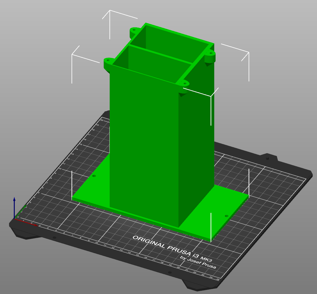
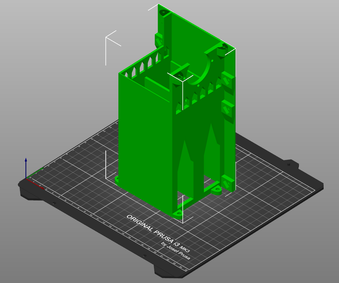
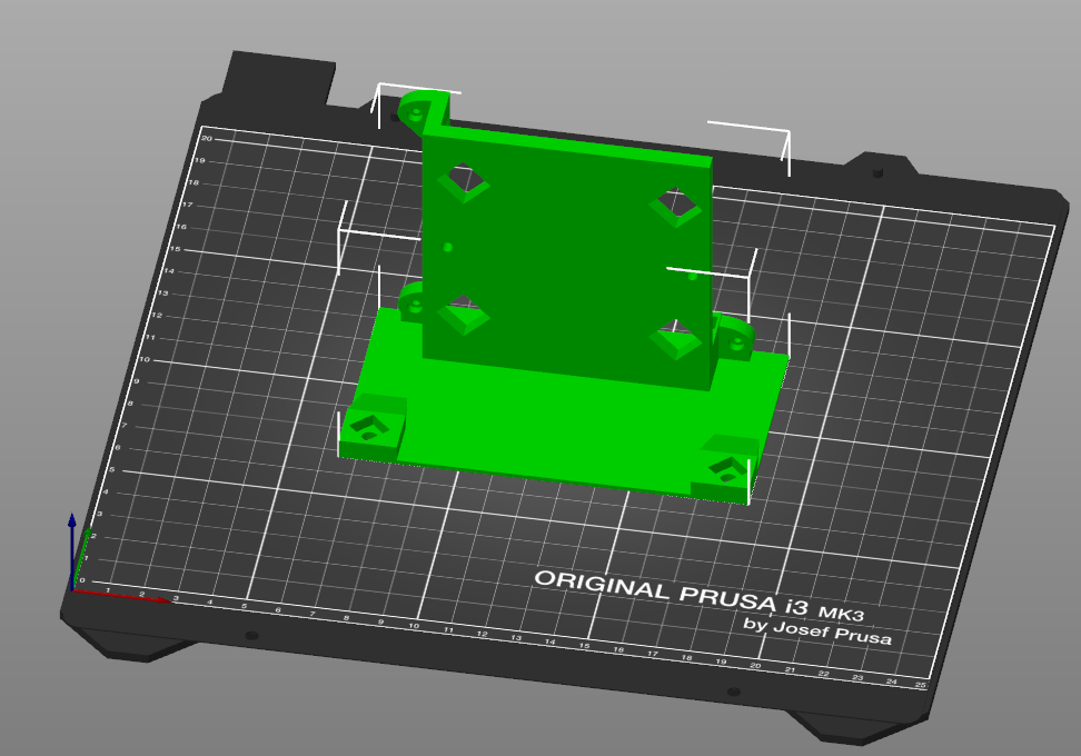
Open your slicing program. Orient the pieces as shown. Infill at 100% for a good solid print. Use a minimum of 5 perimeters. Zero supports. I also recommend you use a seam position of "Nearest".
![]()
![]()
![]()
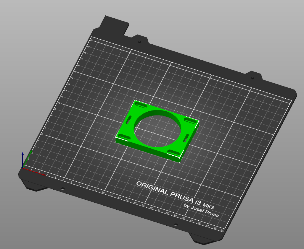
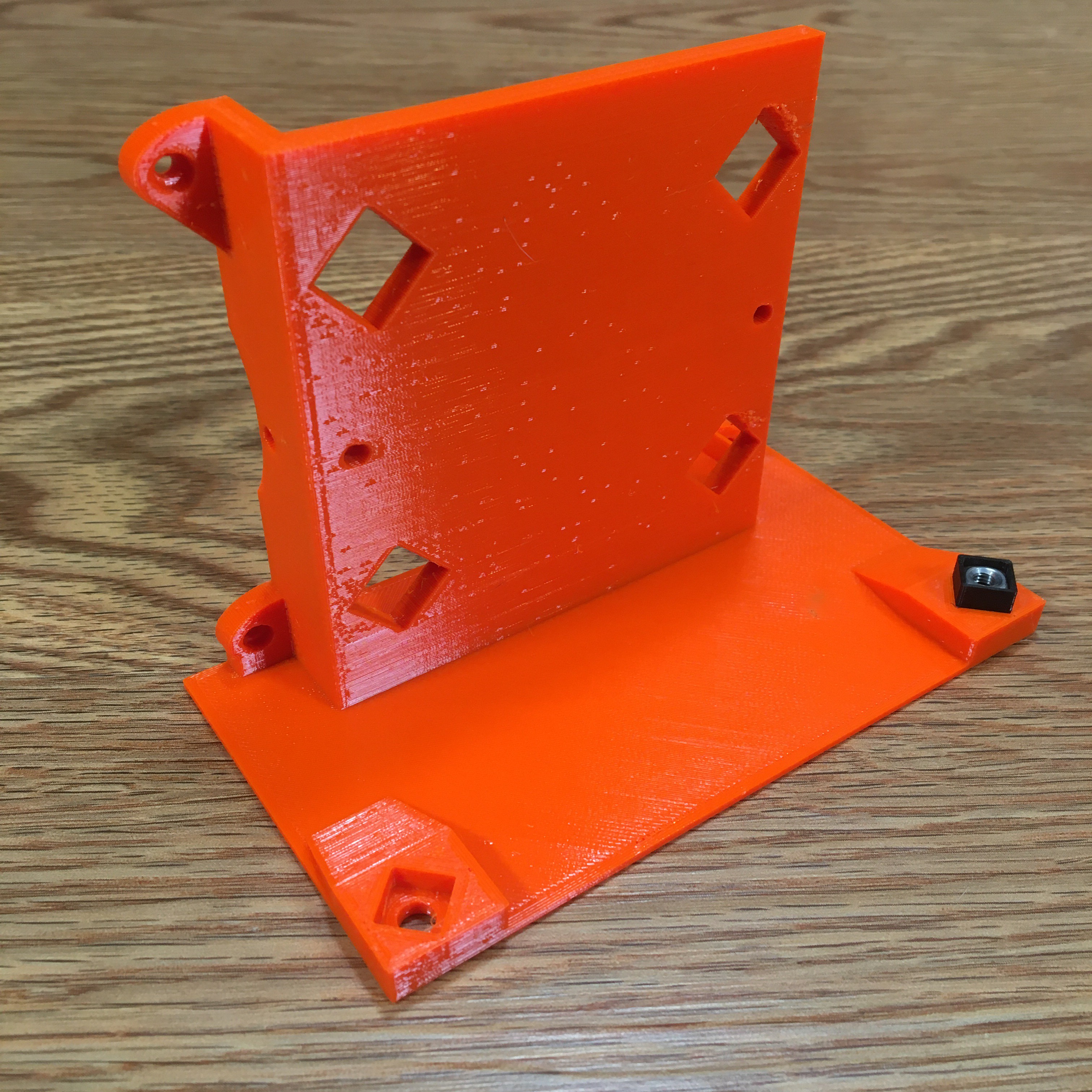
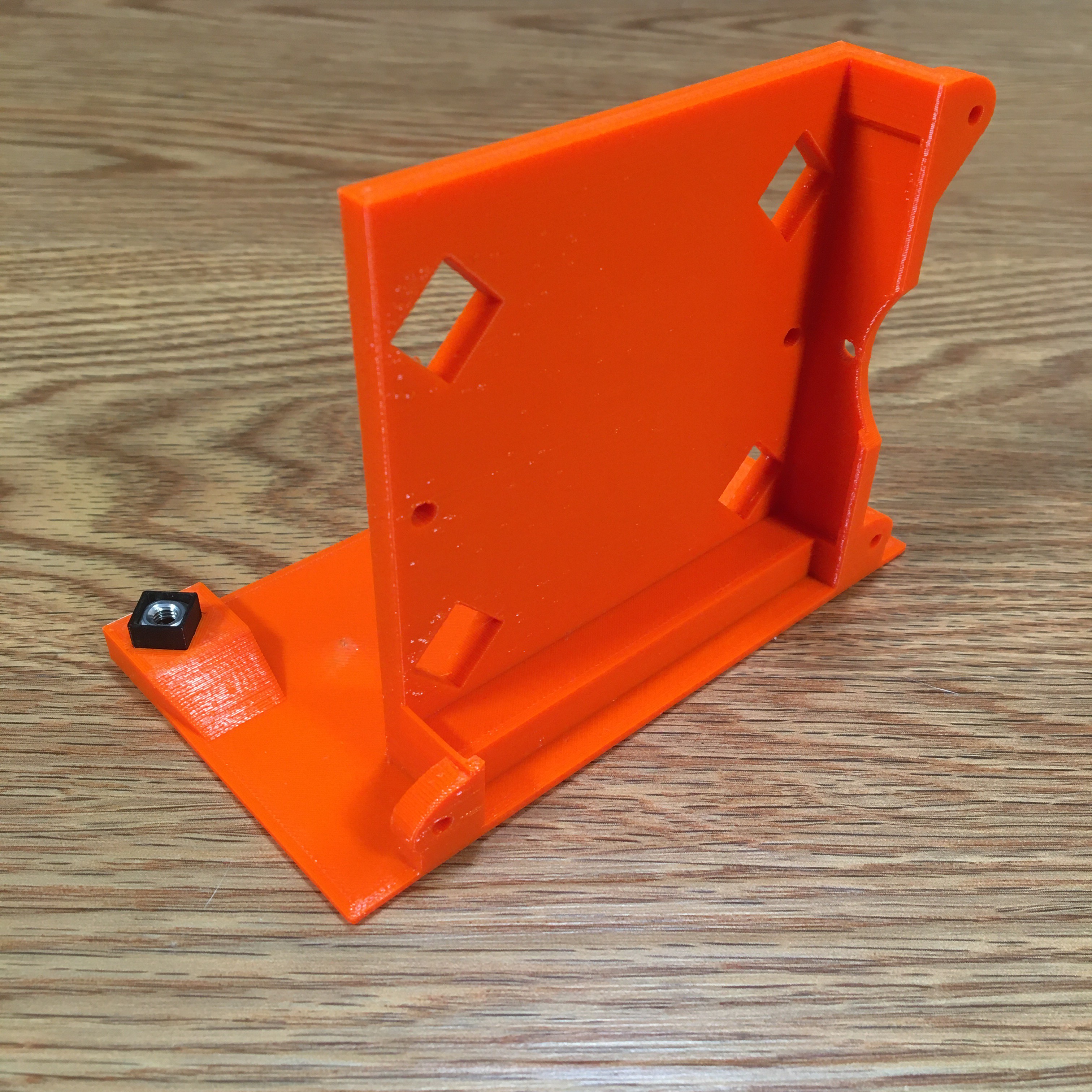
Ok, so I lied when I said nothing in this project needs supports. This next image is of the PDB Circuit Mount. When you lay it on this side, supports are only needed in the two small slits. Also, I highly suggest you stick with 5 perimeters and don't drop below 25% infill.
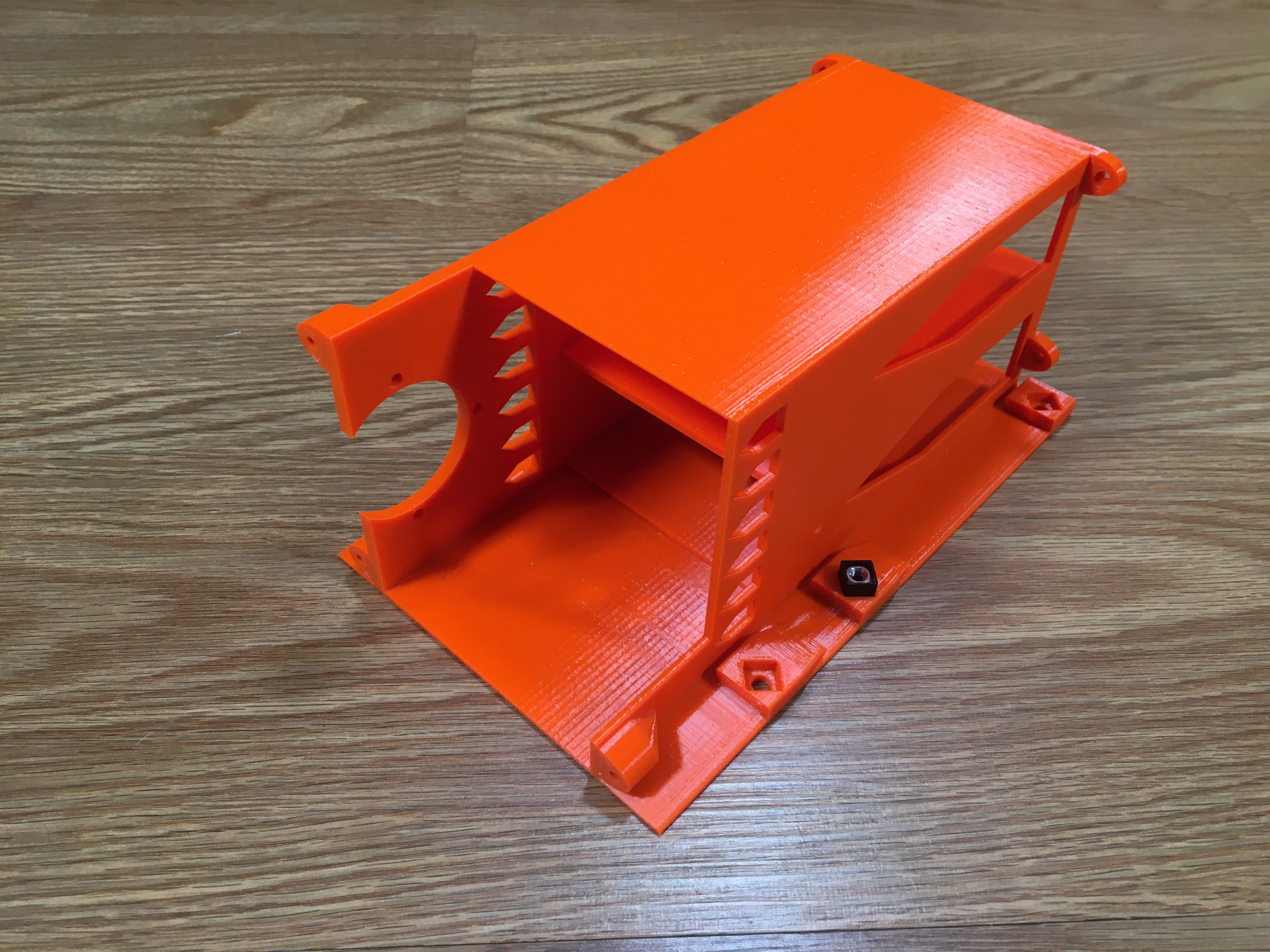
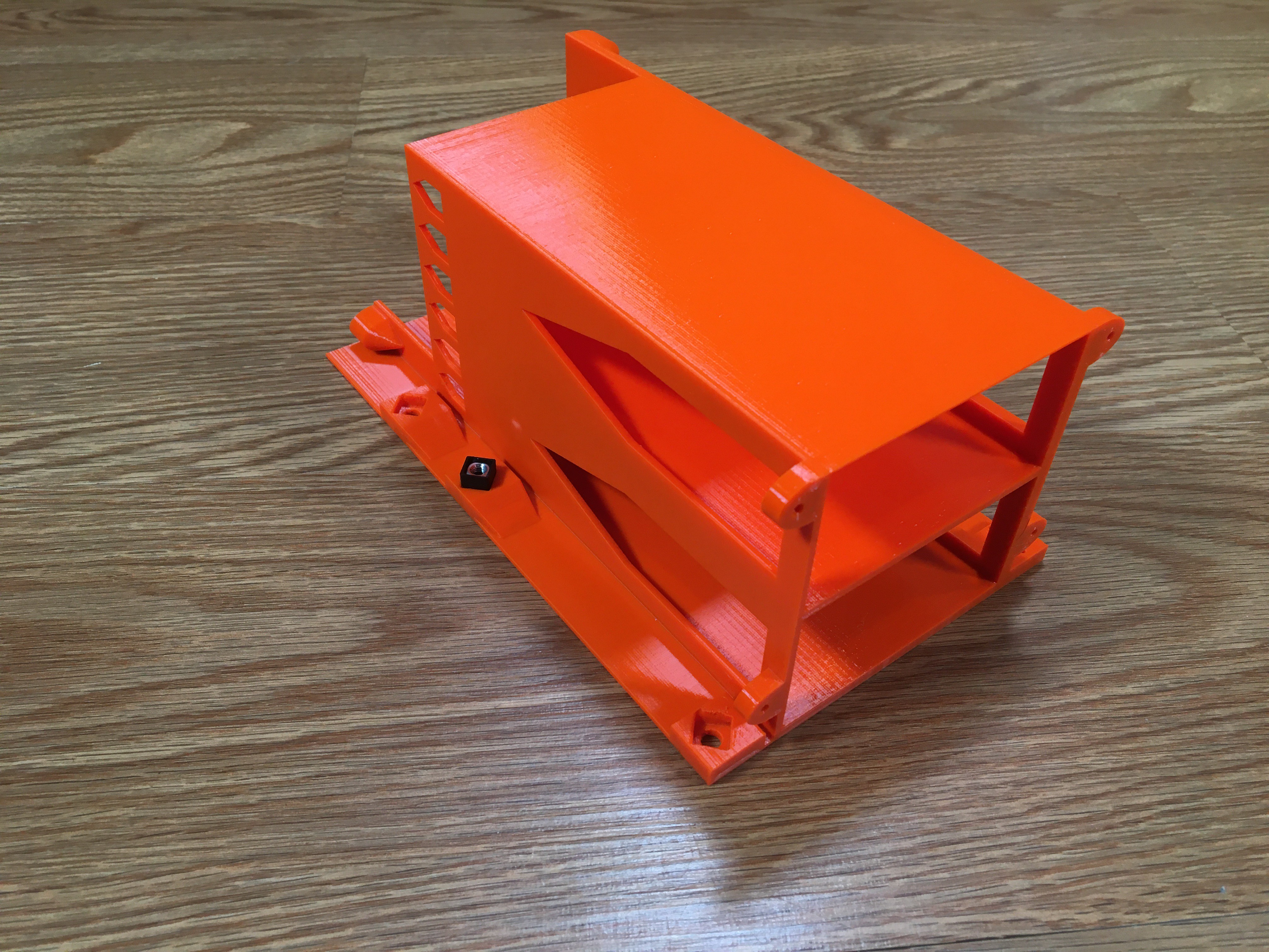
![]() When printed, they should look like this:
When printed, they should look like this:
Supermicro to ATX Power Supply Adapter
Mount a redundant Supermicro PSU in an ATX chassis
 Turranx


 When printed, they should look like this:
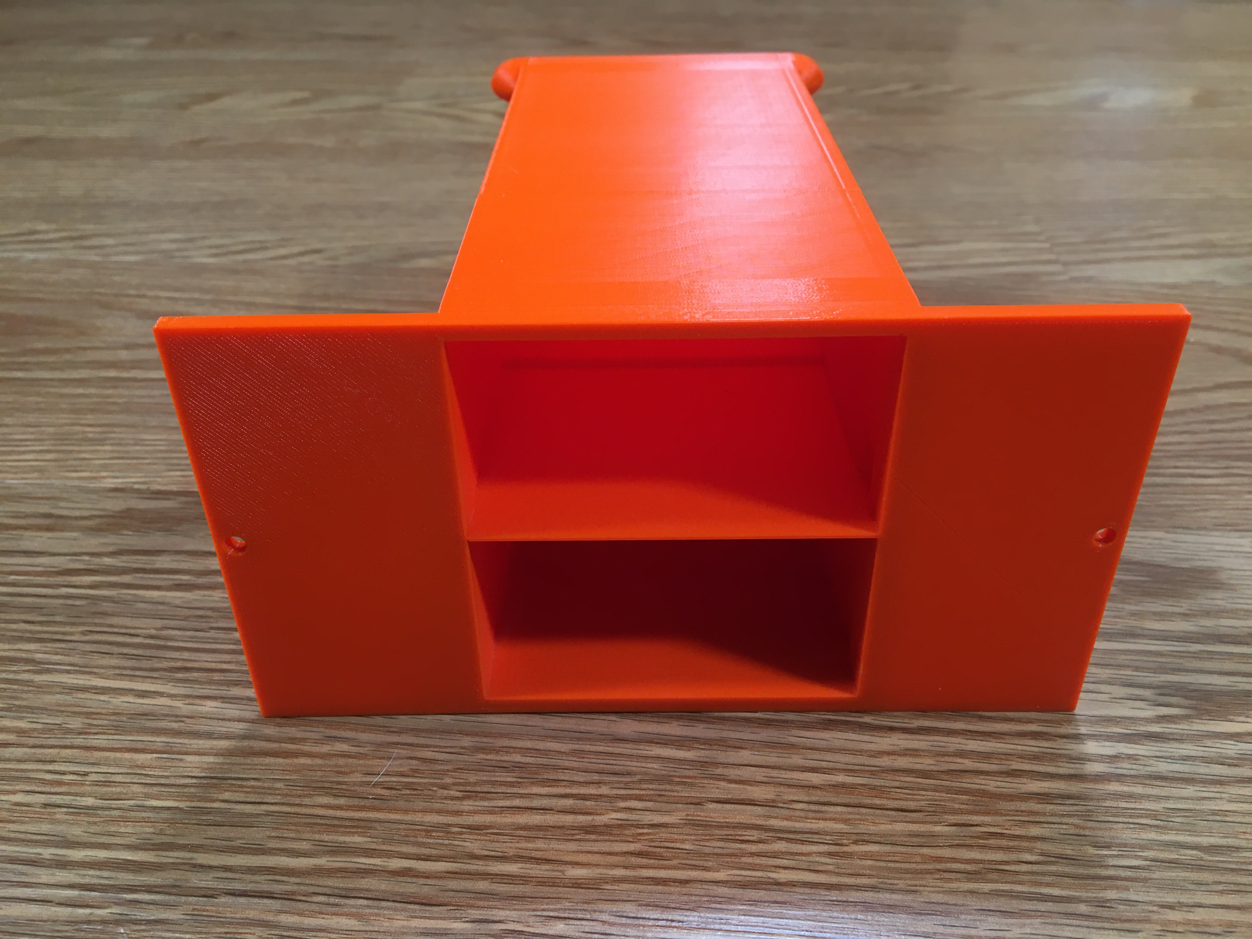
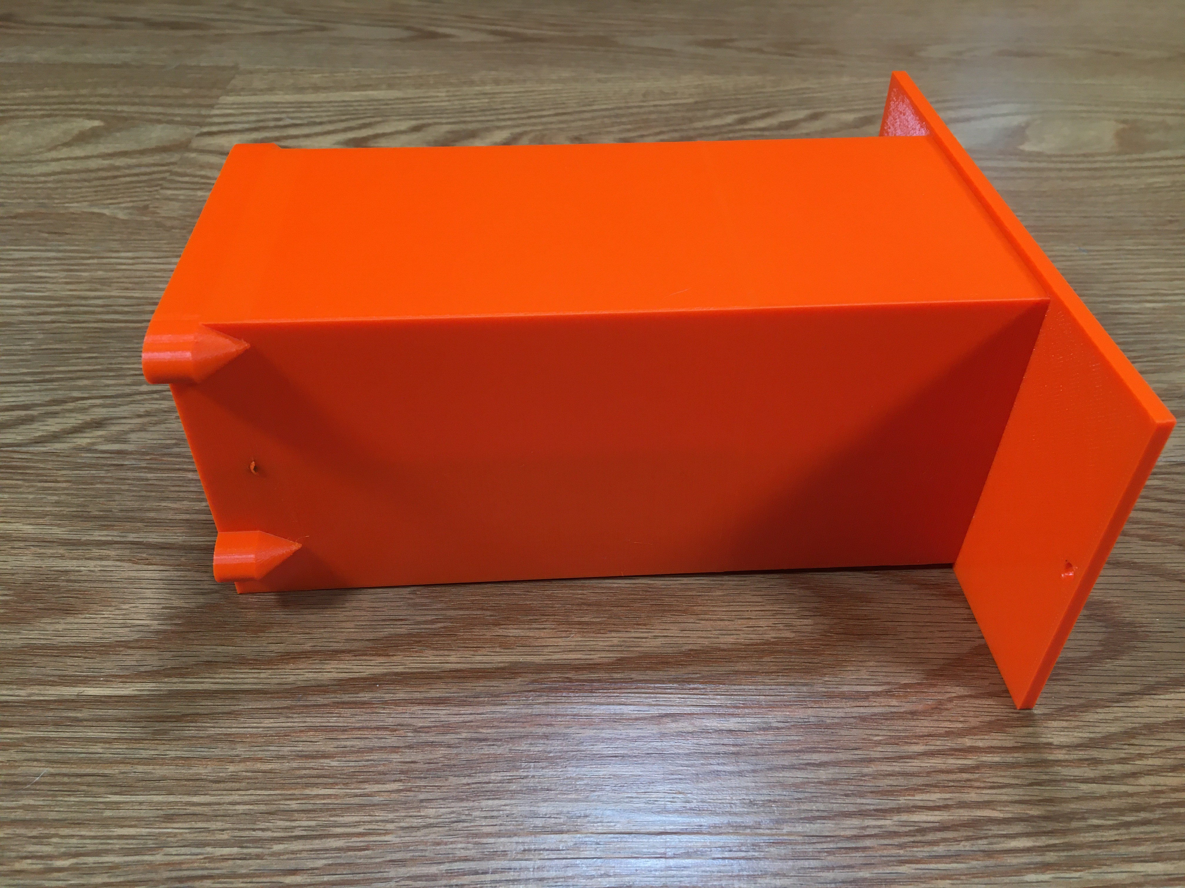
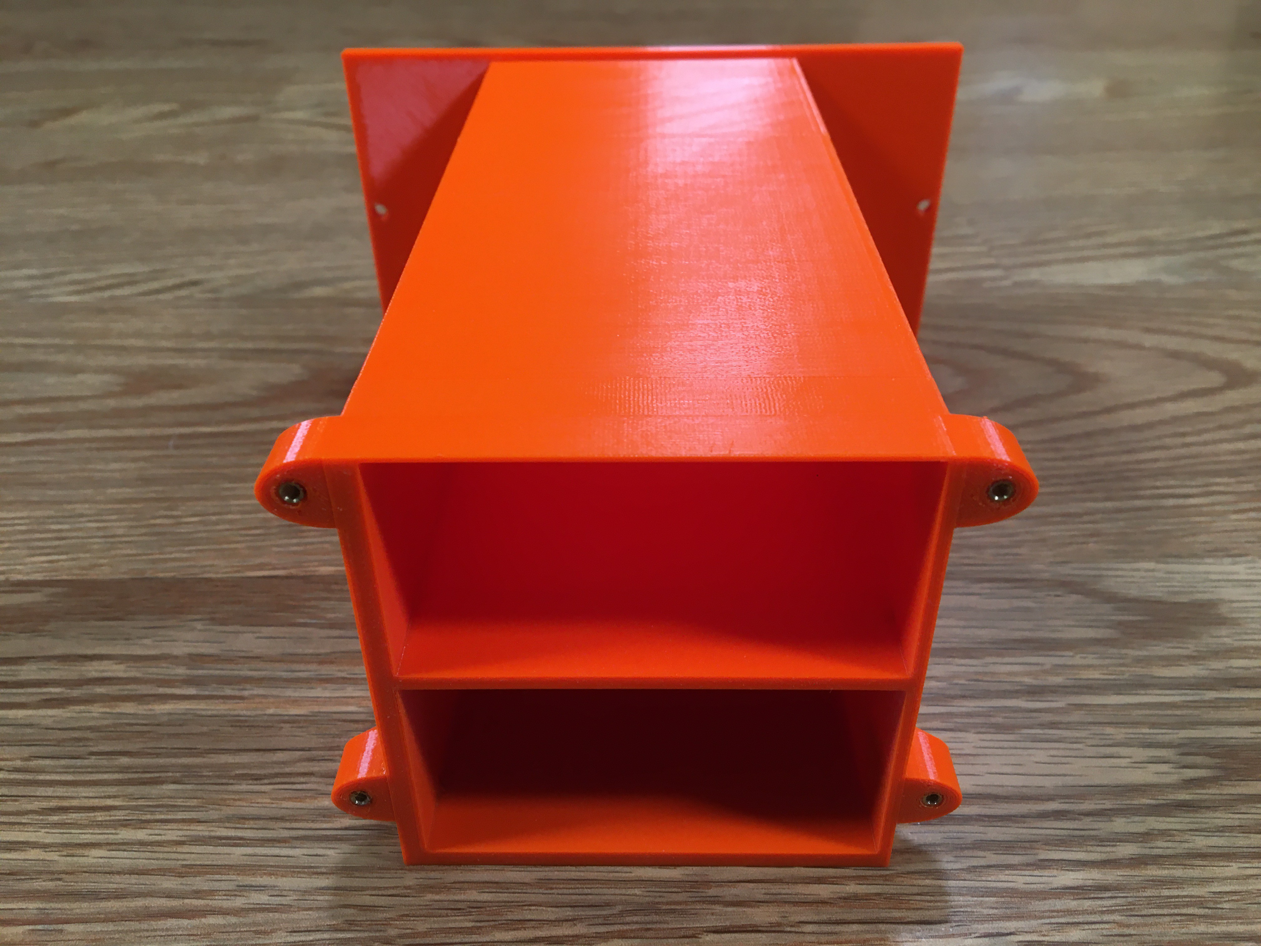
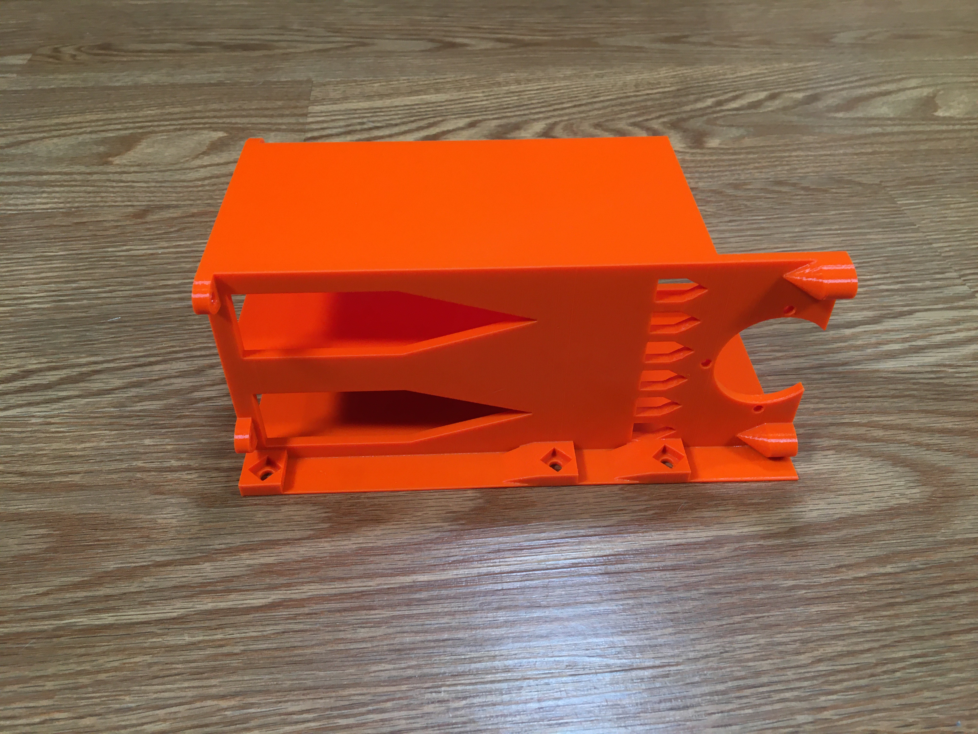
Discussions
Become a Hackaday.io Member
Create an account to leave a comment. Already have an account? Log In.