-
11Install the brass threaded inserts
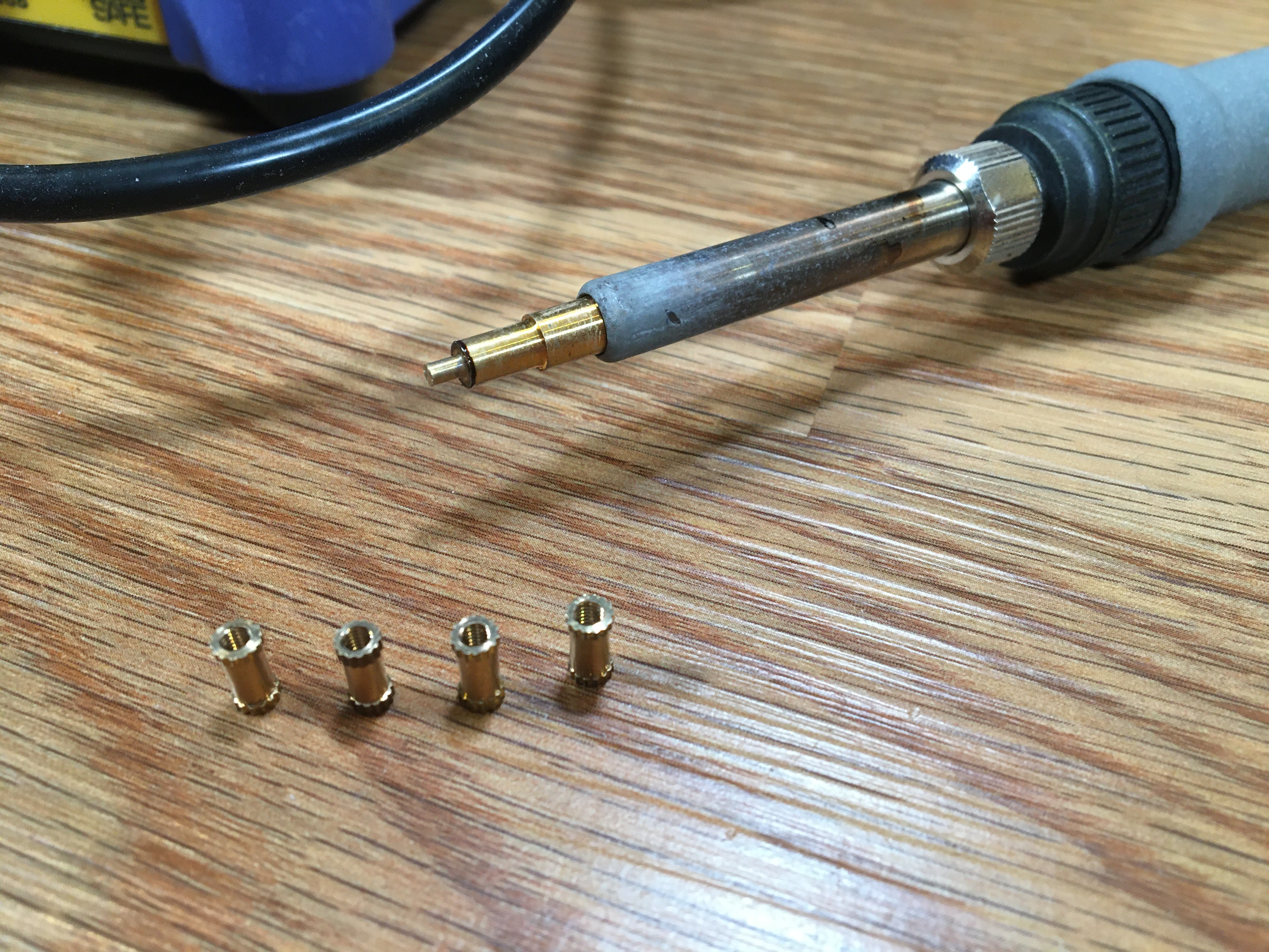
Reach for your soldering iron. Install the 'heat-set insert tip'. Set the temperature to nearly 400 C. Gather your seven brass threaded inserts.
The brass inserts go where the blue arrows are.
![]()
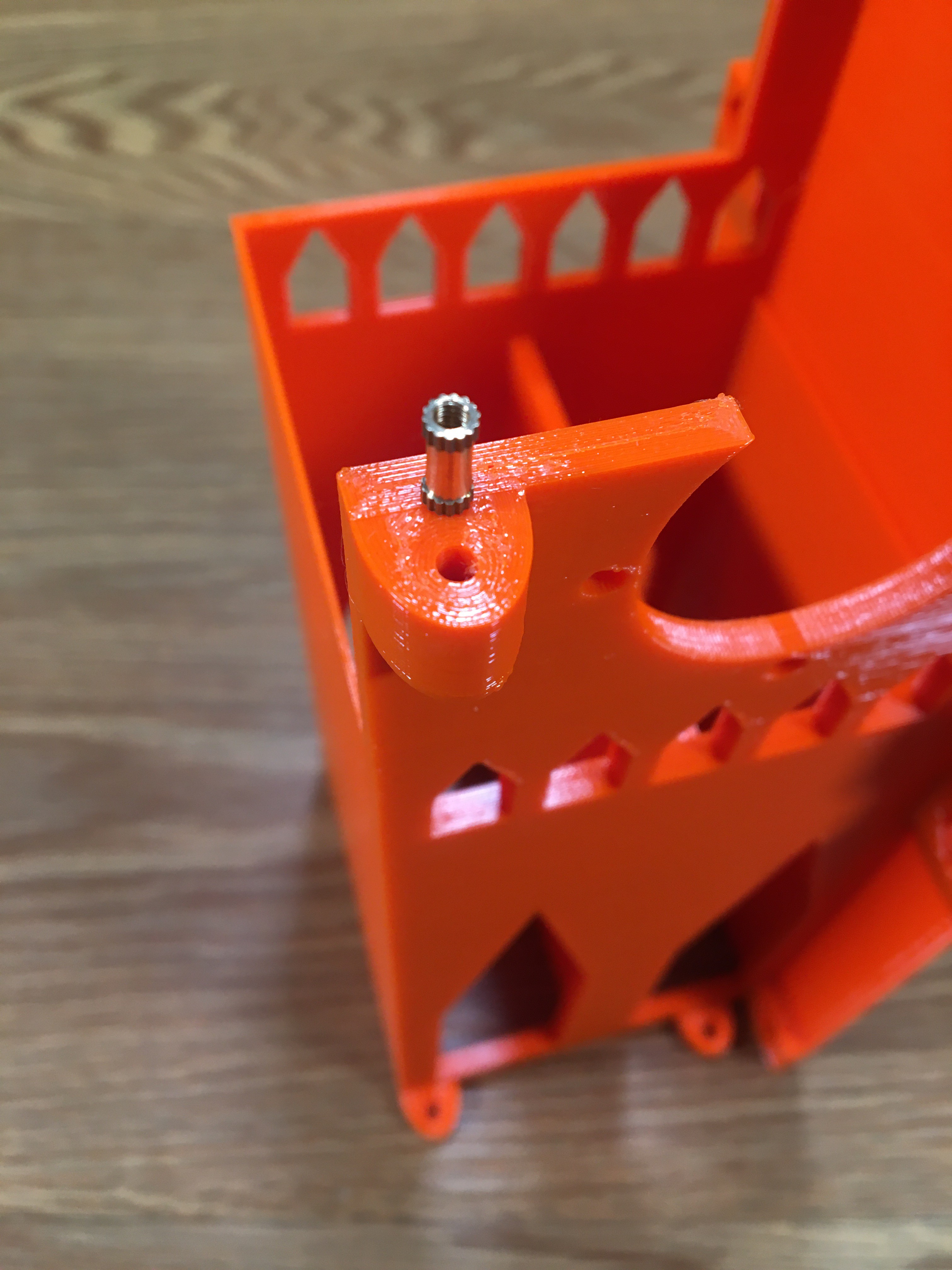
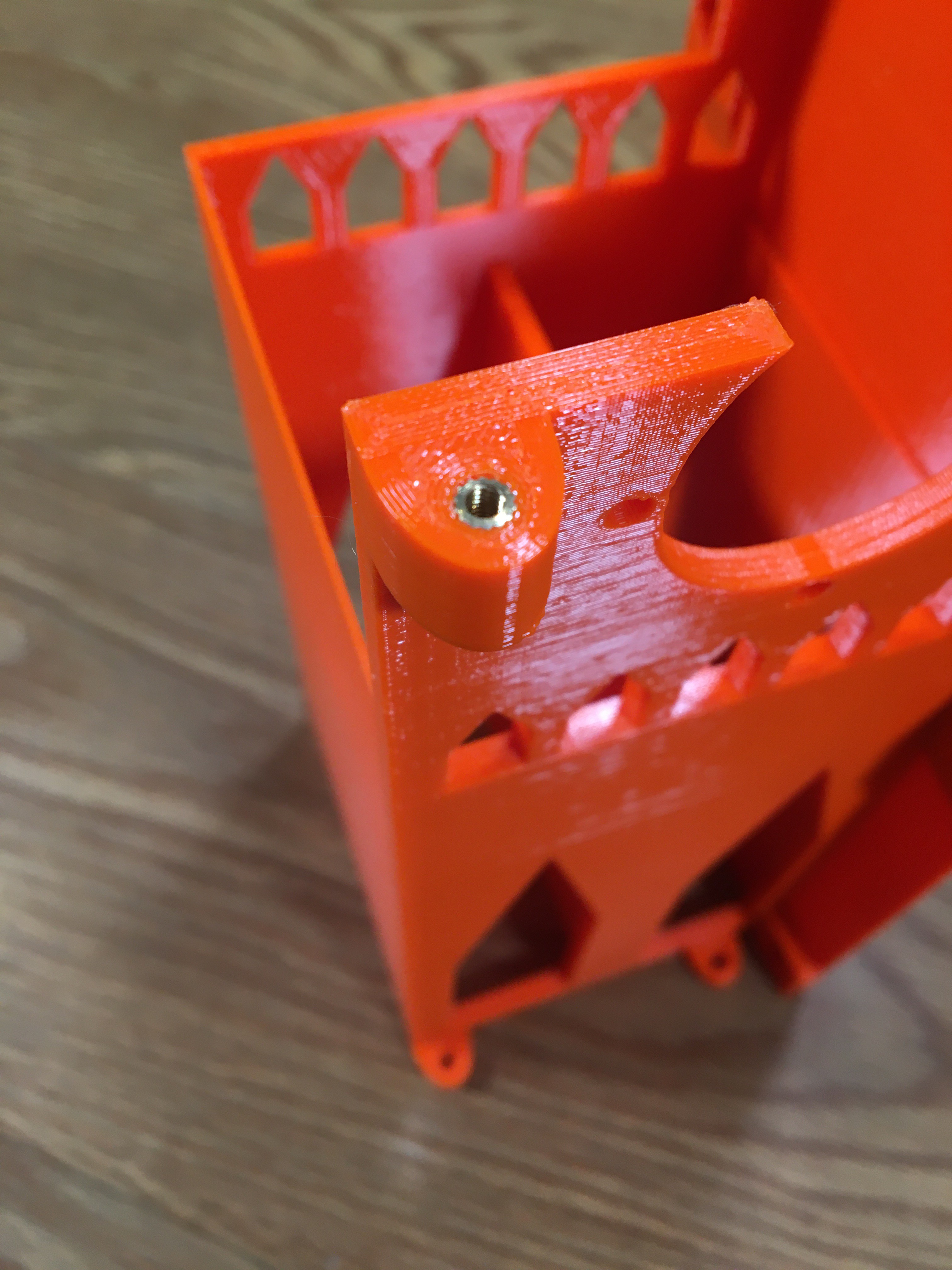
Put the brass insert over the hole. Use the perimeters of filament around the hole to guide you into centering the insert. Put the tip of the soldering iron into the hole of the insert. Press down very gently. After a few moments, the brass insert will start to melt the filament and descend into the hole.
Before:
After:
Rinse and repeat six more times.
-
12Print eight nut cages, install the nuts, install the cages
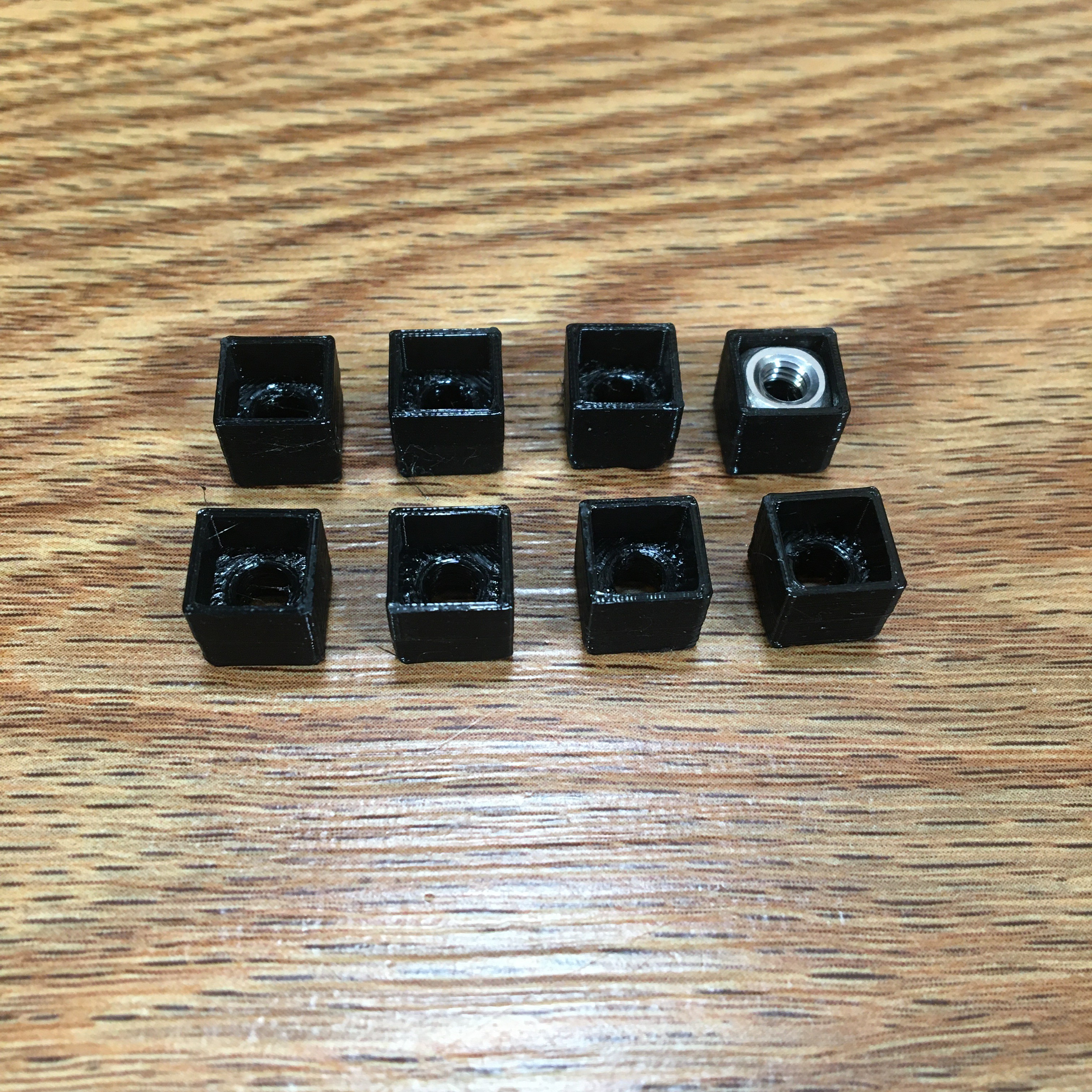
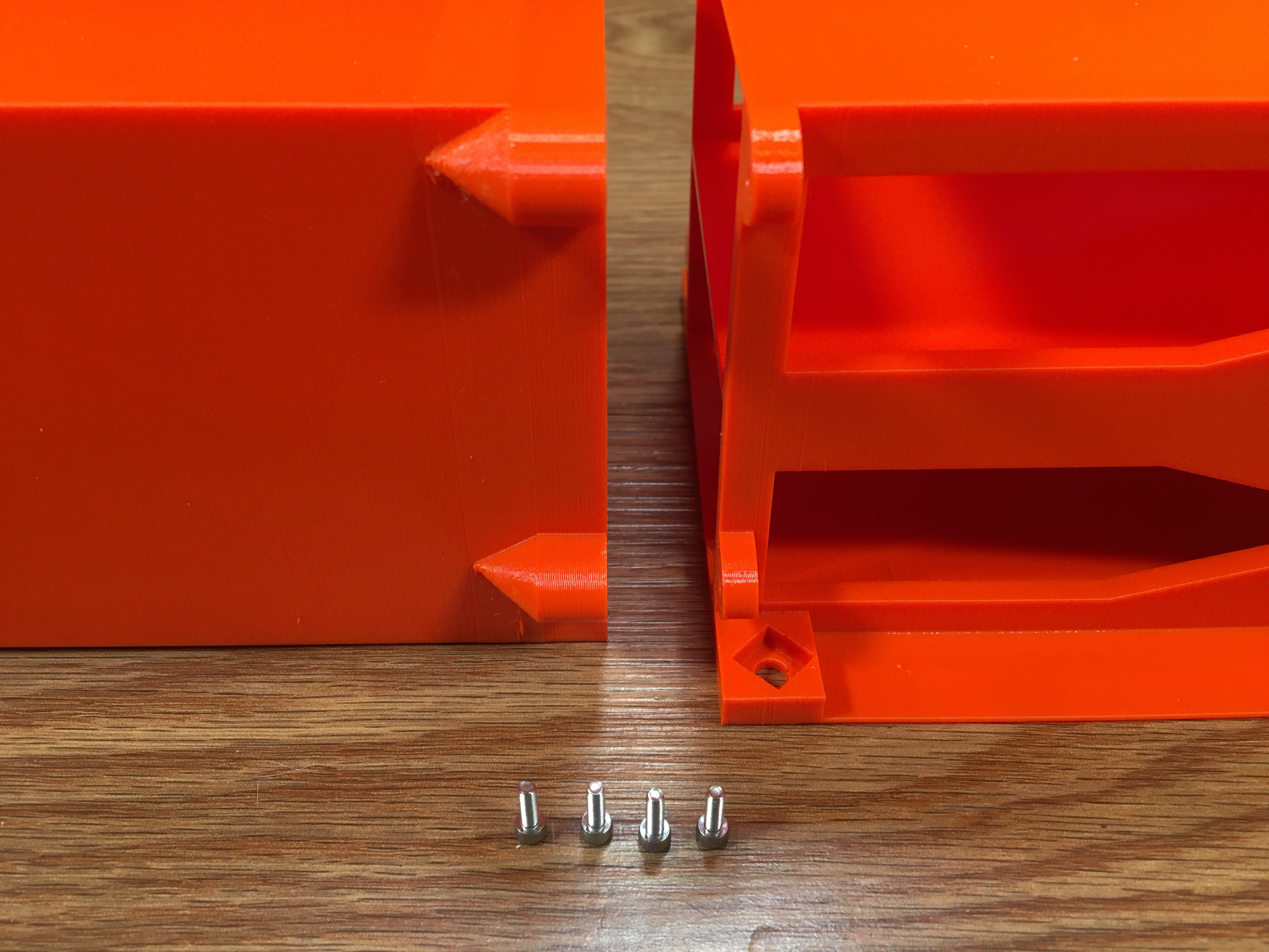
I know that hex/square nuts vary (ever so slightly) in size. Also, the print that comes off your model will also be slightly different than mine. Therefore, when I designed the Middle Third and PDB Third, I purposely made the holes where the nuts go to be over sized. I reasoned that I could print out the Thirds in one shot, then mess around for a couple hours creating nut cages (shown below) that would snugly hold the metal nuts and also snugly fit into the Thirds. I've included the STL file for the Nut Cage, but you will probably want to design your own.
To give you a hint, the walls of these cage nuts are only 2 perimeters thick with a 0.4 nozzle.
Once they are printed, install the eight M4 square nuts, then install all eight cage nuts into the Middle Third and PDB Third. -
13Connect the AC Cable Third to the Middle Third
Grab four M2.5x6mm bolts (screws?) and connect the AC Cable Third to the Middle Third. They don't need to be super tight.
-
14Assemble the PDB Third
Grab the following items:
- PDB Circuit Mount
- PDB Third
- M3x16mm bolts (two)
- M3 hex nuts (two)
- M3 washers (two)
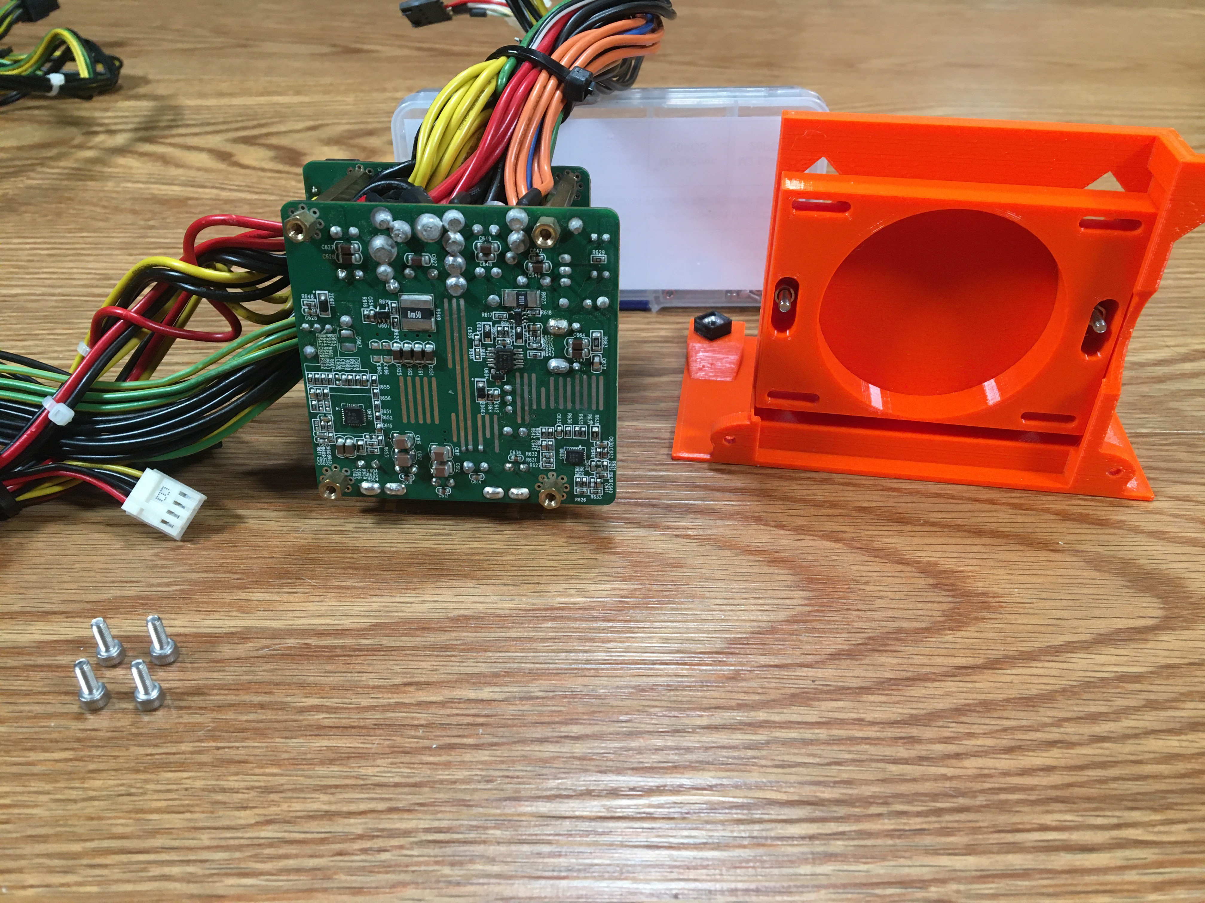
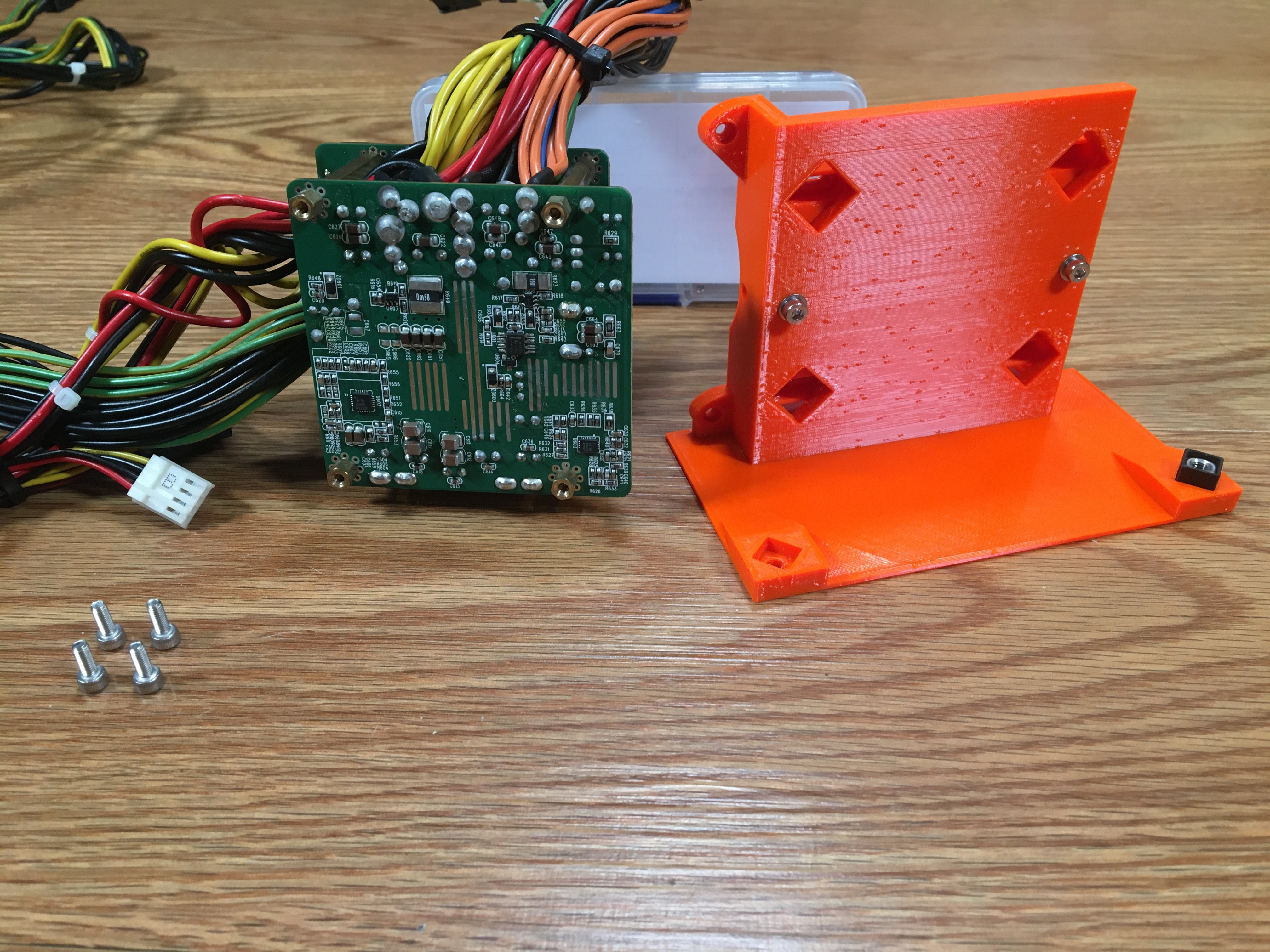
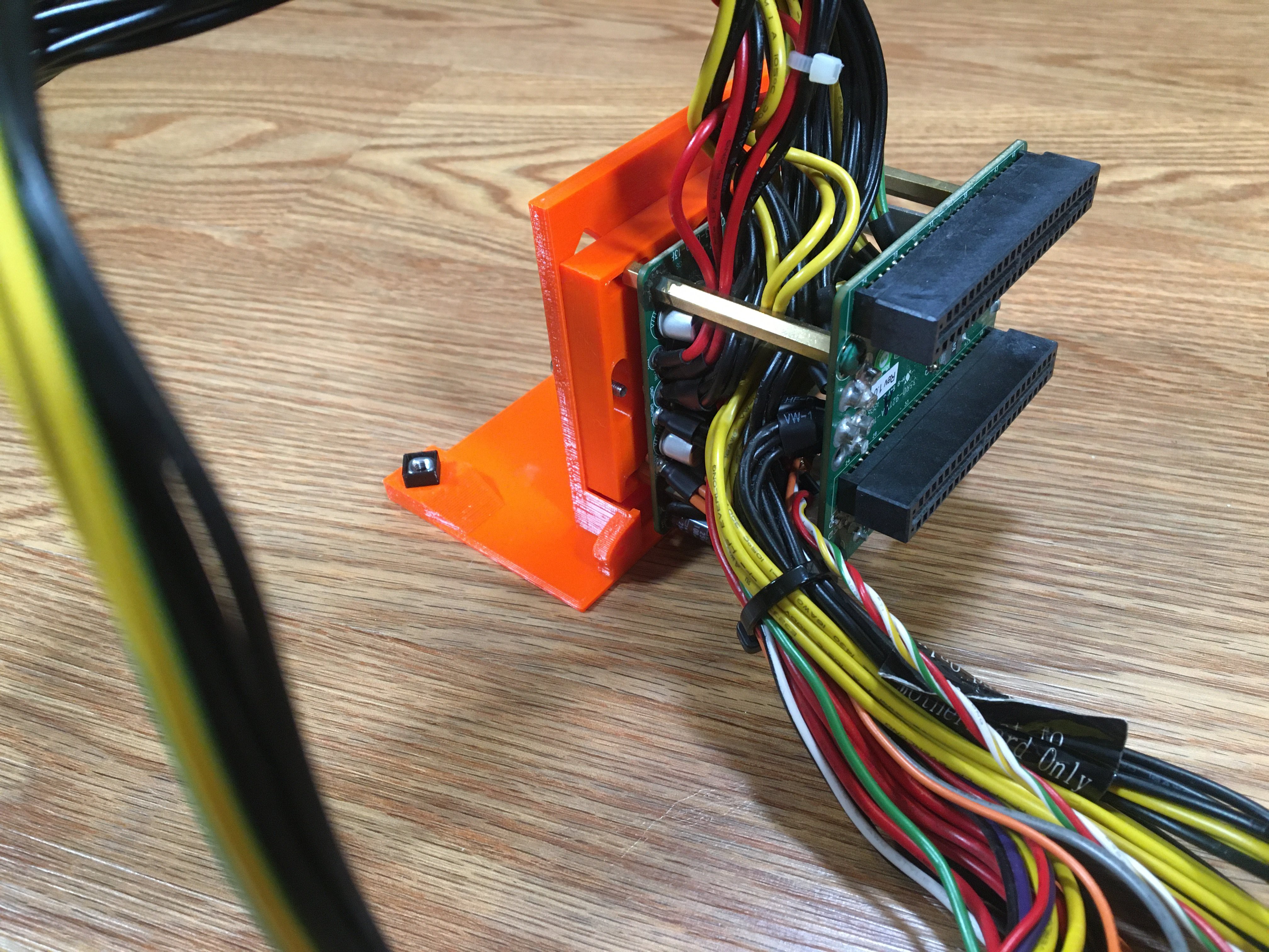
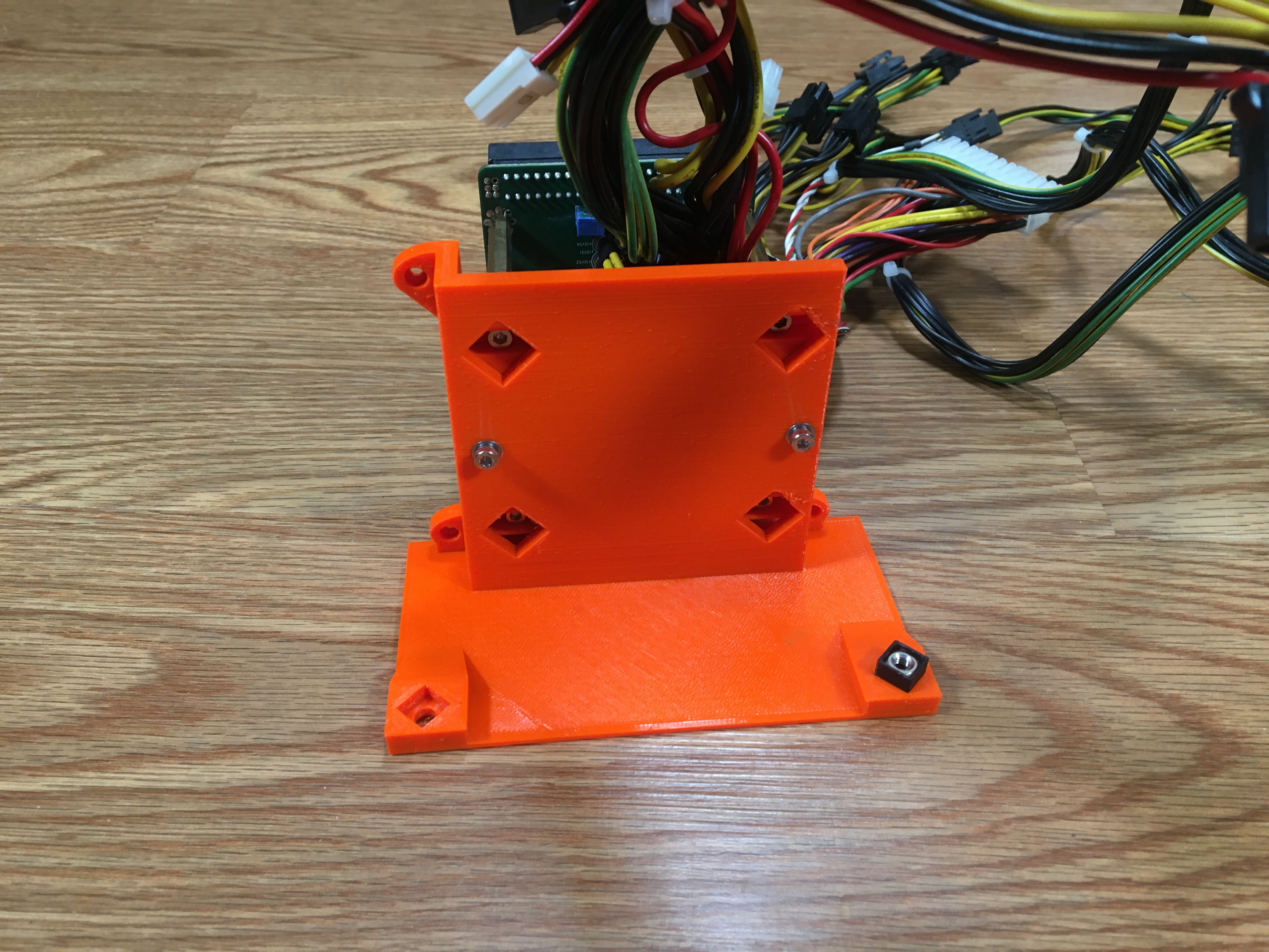
Mount the PDB Circuit Mount to the PDB Third. Note which slots look wide and which slots look narrow in this photo. The vertical slots are wide. The horizontal slots are narrow. This will help you with the orientation of the PDB Circuit Mount.
The vertical slots are just wide enough to keep an M3 hex nut from turning, but still allow it to slide up and down.
-
15Mount PDB on PDB Third
Grab four M3x8 bolts. Use these to secure the PDB to the PDB Third.
NOTE: All six bolts in the PDB Third should be loose enough to allow the PDB to slide up/down and left/right. We will tighten them later.
-
16Join all three Thirds
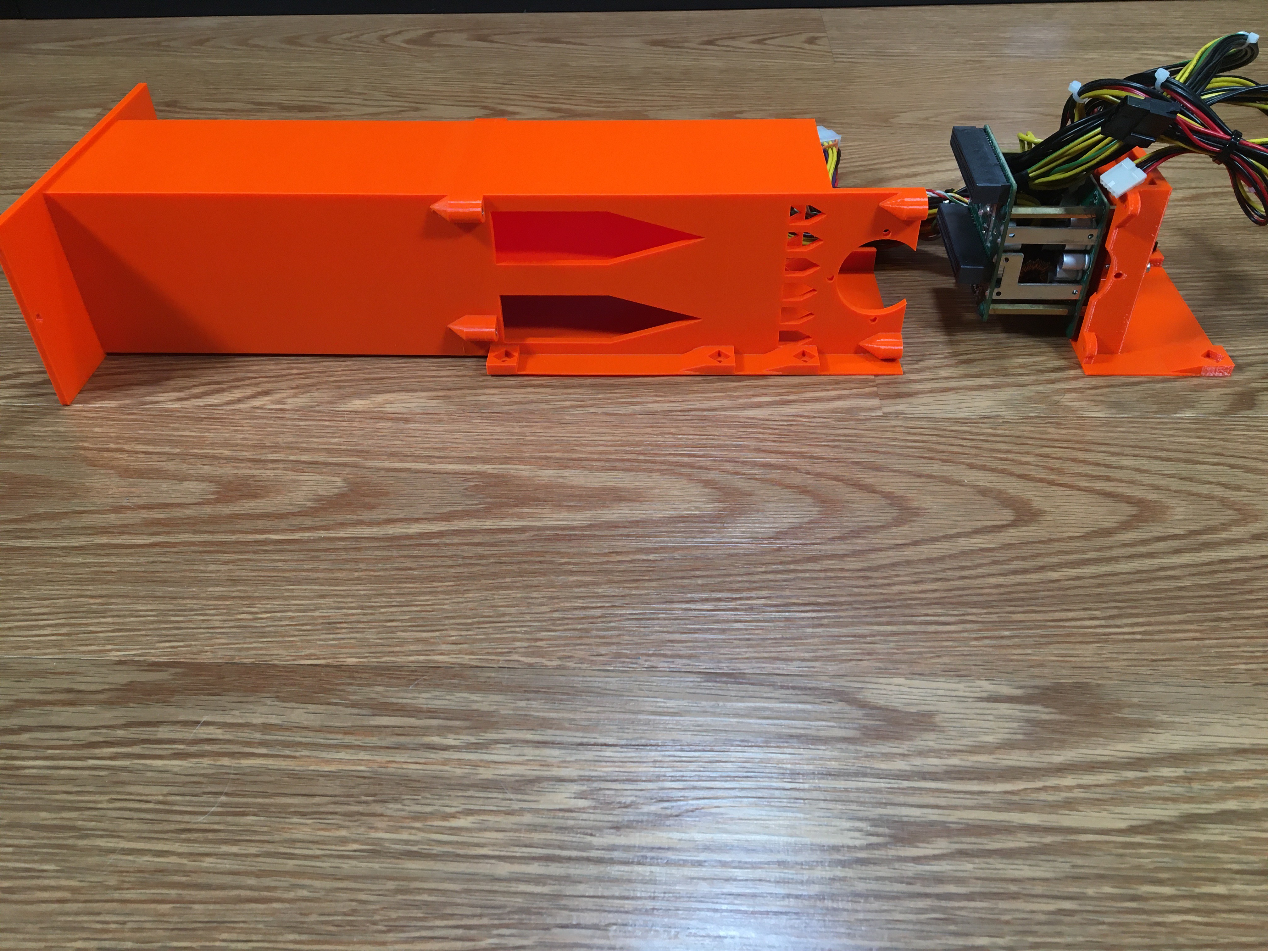
Grab three M2.5x6mm bolts. Use them to join the PDB Third to the other two Thirds.
-
17Align the PDB
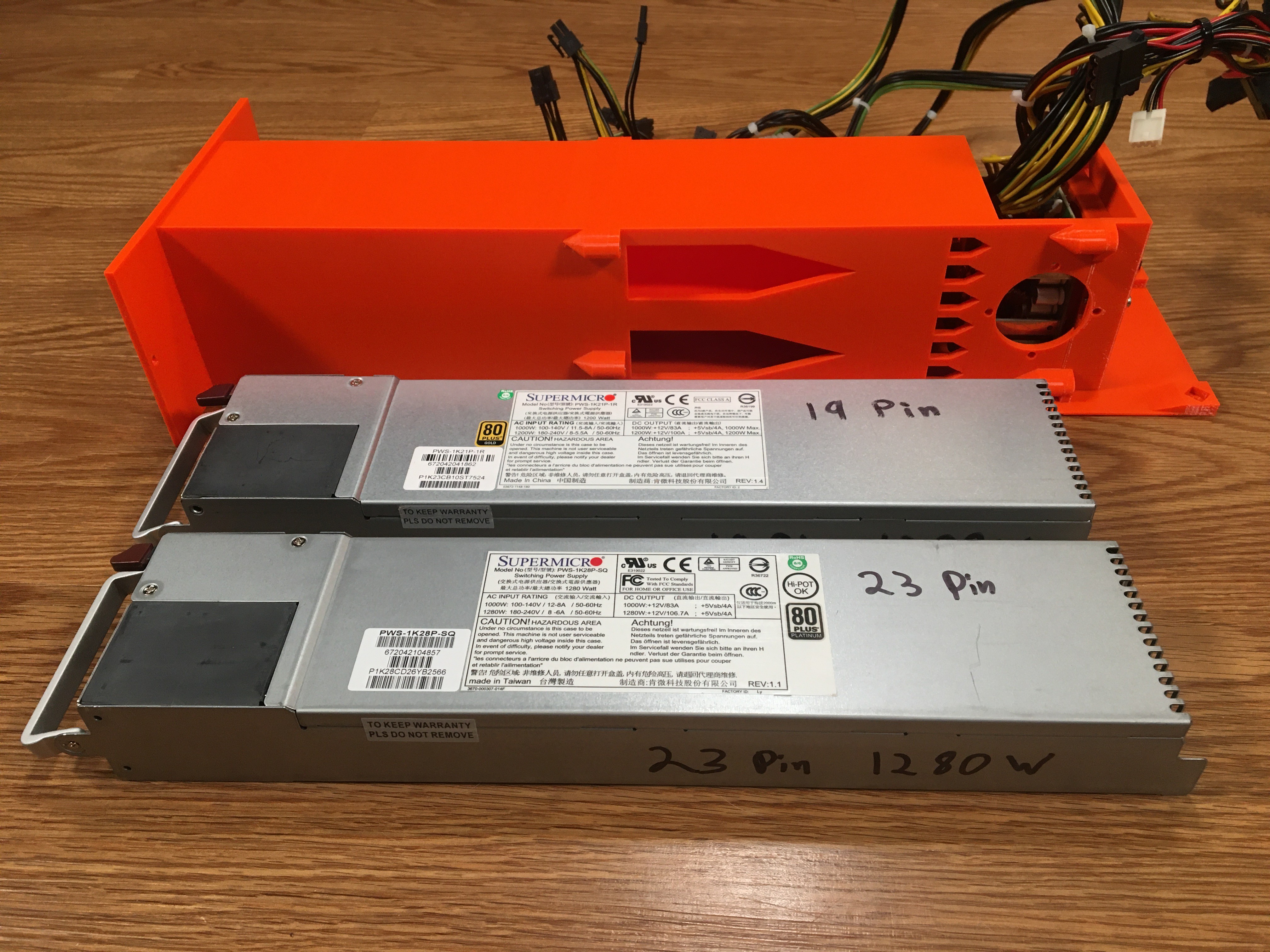
Grab the assembled product and your two Supermicro power supplies:
Slowly push one PSU into the assembled product and adjust the PDB up/down and left/right until the PSU tab slides into the PDB slot. Just before the PSU can't slide back any more, you will hear a click as the PSU release latch springs outward into a little hole inside the print.
Slowly push the second PSU into the assembled product. Again, you will hear the PSU release latch spring outward.
After both PSUs have been slotted into the PDB, tighten down the six bolts on the back side of the PDB mount.
-
18Partial disassembly
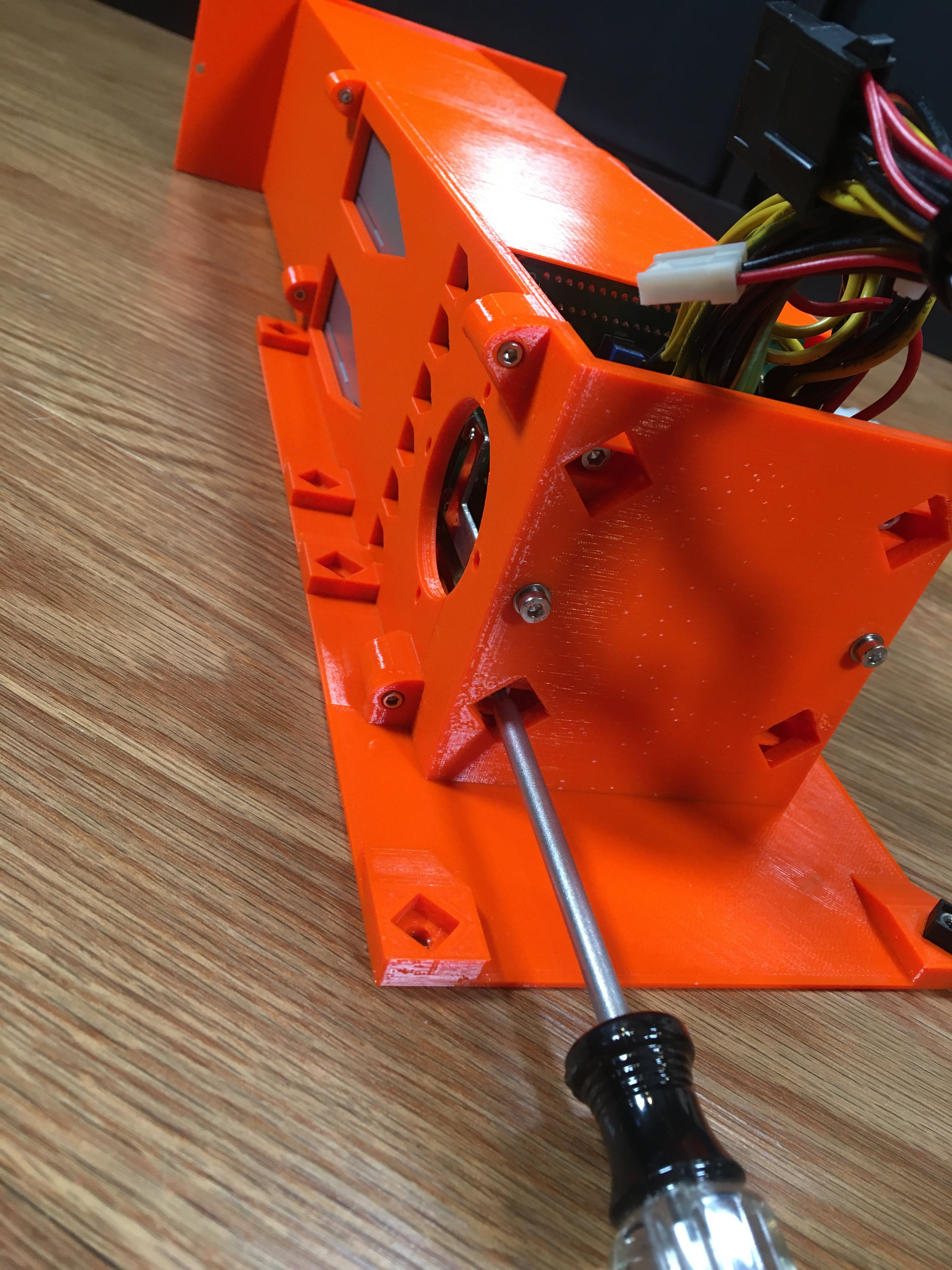
Remove the two PSUs. Unscrew the three M2.5x6mm bolts that connect the PDB Third.
-
19Install the 40mm fan
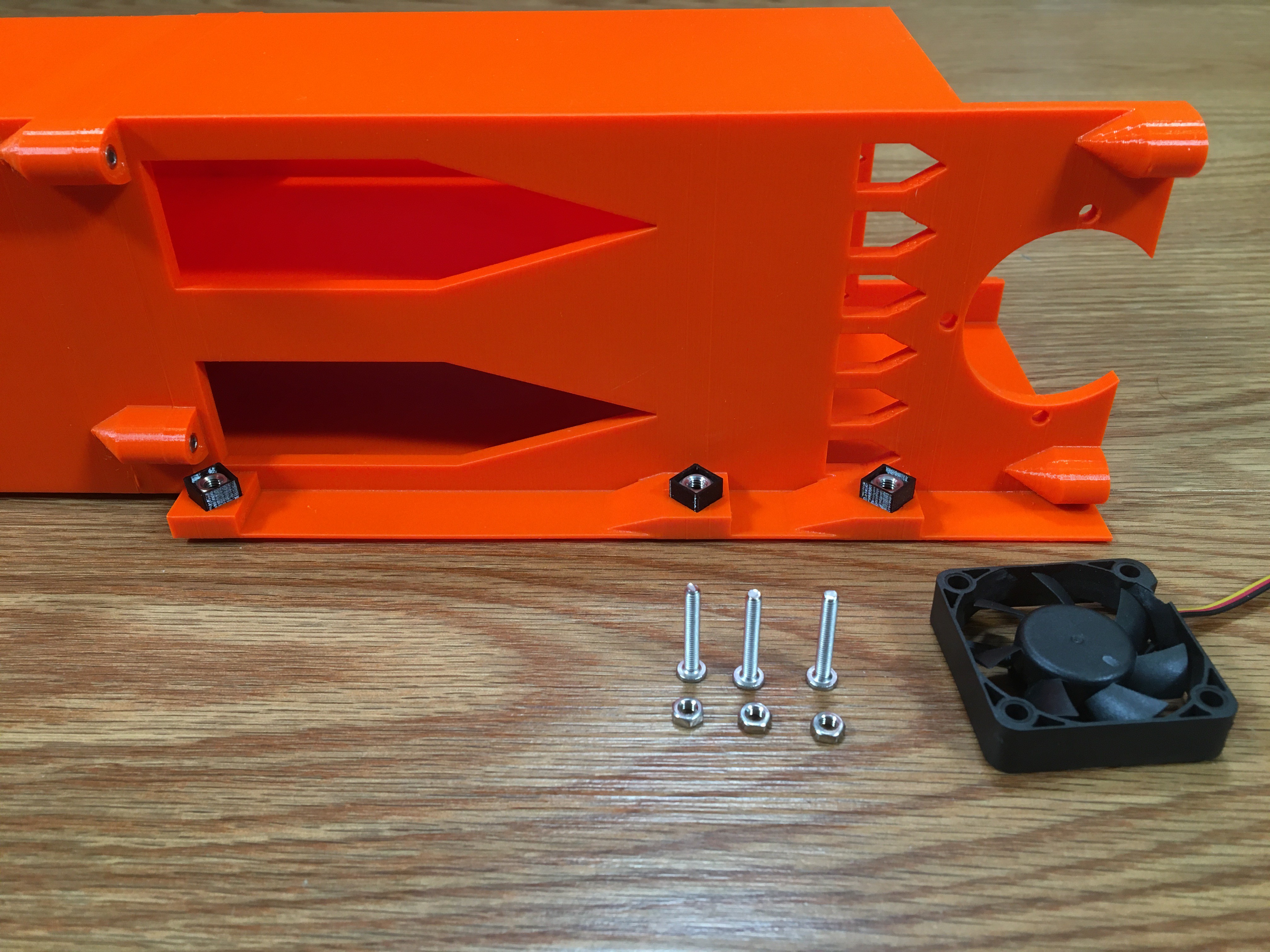
Grab three M3x12 Flathead bolts and three M3 hex nuts.
Before:
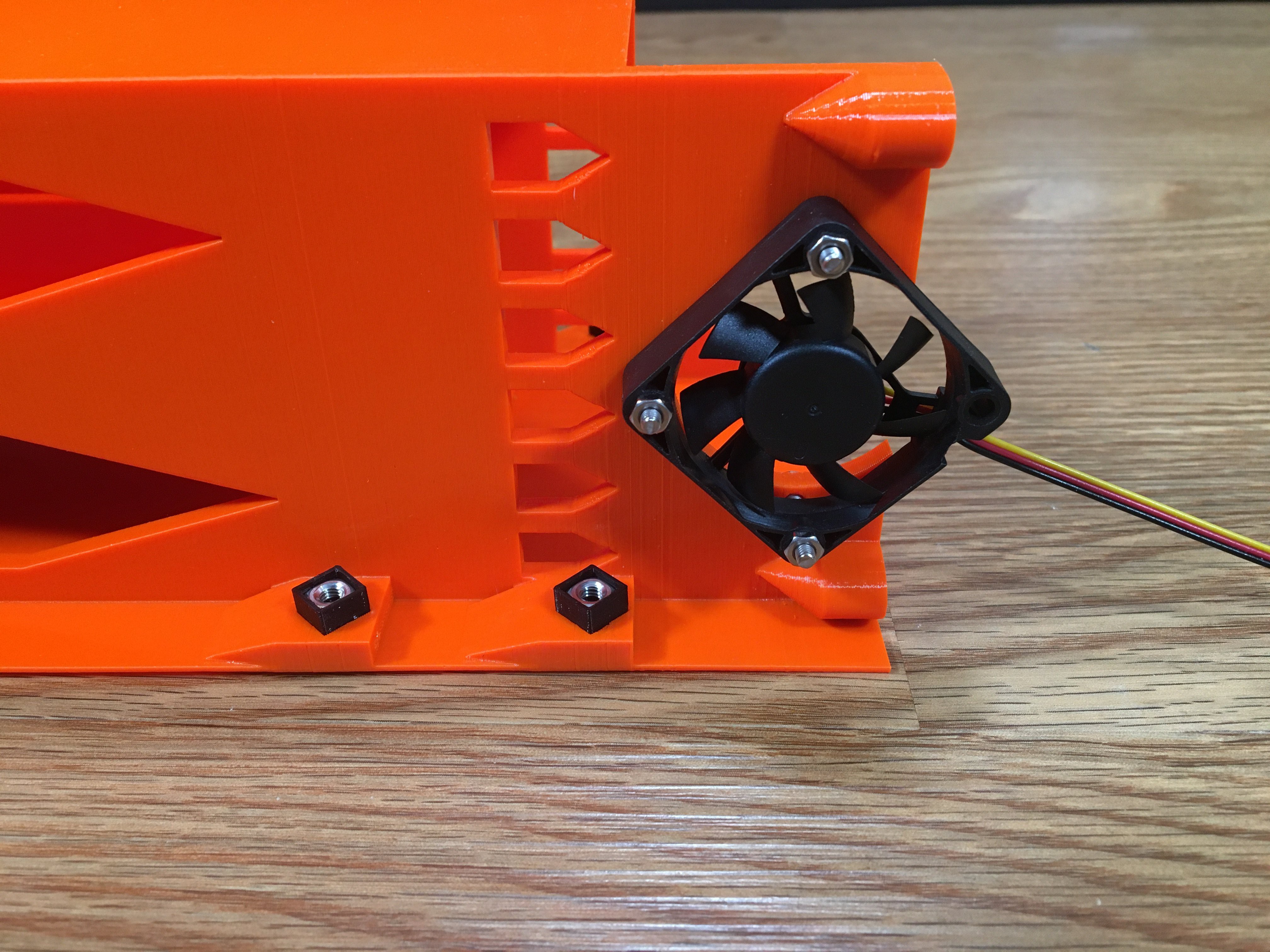
Install the fan so it blows into the print. Put the Flathead on the inside of the print and the hex nuts on the outside.
After:
-
20Remove the ATX PSU mounting plate
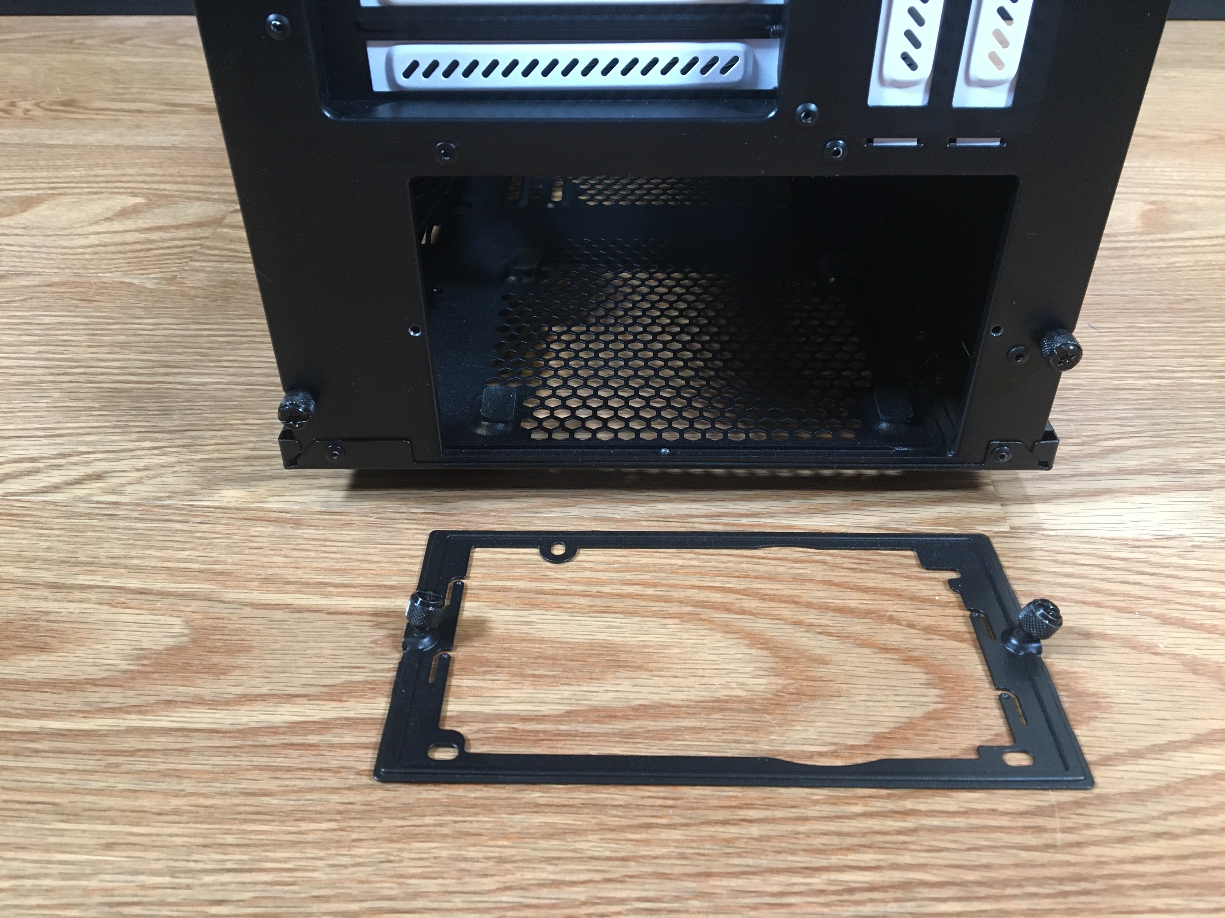
The Fractal Define S2 chassis has an ATX PSU mounting plate. Take it off and give it to someone you cherish. (Awww....)
Supermicro to ATX Power Supply Adapter
Mount a redundant Supermicro PSU in an ATX chassis
 Turranx

 To give you a hint, the walls of these cage nuts are only 2 perimeters thick with a 0.4 nozzle.
Discussions
Become a Hackaday.io Member
Create an account to leave a comment. Already have an account? Log In.