-
Turning a Sketch into Reality
04/06/2021 at 20:48 • 0 commentsI haven't posted anything in the last few days, but I haven't been (only) loafing over the Easter holiday.
I spent some time on Saturday putting together the framework of a PyQt5 project to do the data analysis.
I got back to it this evening, and implemented parts of the GUI.
![]()
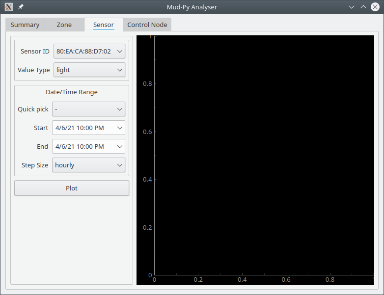
I started with the somewhat simpler single sensor plot.
It follows the sketch fairly well, expect that I added some additional features.
The "Sensor ID" and "Value Type" fields are filled from the Mud-Py database - I've already implemented that part. The API is somewhat limited right now, but it just needs a few more methods to get the data for the plot.
The "Date/Time Range" block is a custom control that I built. I'll need it on most of the other tabs, so I went ahead and made a control rather than putting all of the bits and pieces on each tab.
I like PyQt5, but getting those few items to look like they should while still automatically adjusting to the window size and the content was a pain.
At any rate, it is making progress.
25 April is coming up fast, though, so I'm going to have to get moving or else miss the cutoff date for the "Data Loggin'" contest.
As with all the software for this project, the analyser got its own GitHub repository.
-
Data Analysis - Start With a Sketch
04/01/2021 at 18:29 • 0 commentsWith my control nodes quietly collecting data, it is time to start doing some analysis.
The entire point of this project has been to visualize the distribution of the soil moisture in my yard.
I want a heat map, or topographic map of the yard showing the moisture, and I want it animated to show how the moisture changes with time.
I don't know of a standard program that can do what I need (Veusz could probably do it, but I'd have to export the data to csv or something.)
The simplest thing for me is to (again) use the Mud-Py Django project as a library, and write my own analysis software.
That sounds like a lot of work, but it isn't, not really. At least, not if you use the right tools.
The right tools for this are Python, NumPy, PyQtGraph, and PyQt5.
- Python gets me access to Django and the database.
- Numpy gets me easy access to complex math stuff.
- PyQtGraph gets me easy access to powerful, good looking charts.
- PyQt5 lets me join all the parts in an easy to build GUI.
I'm sure it is possible to do all of the needed things completely inside Django using Leaflet for the graphing, but that would require more contact with HTML and Javascript than I want to subject myself to.
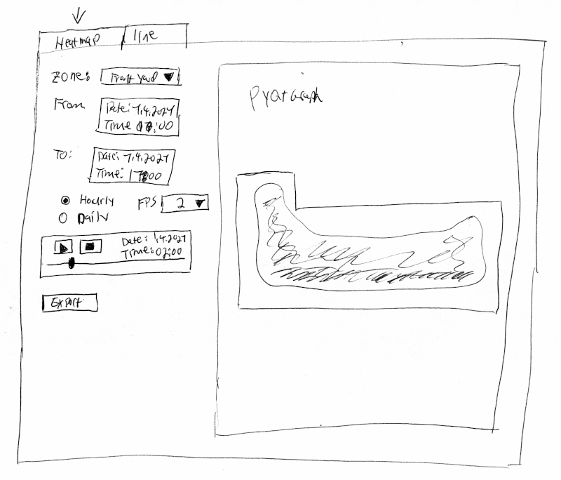
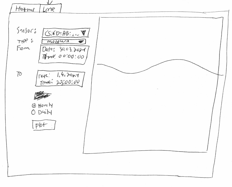
Before I start on GUI projects, I usually make a rough sketch. There are two this time around: One for the heatmap/topographic chart, and one for a line chart.
Heatmap:
Line chart:
I did say they were rough sketches.
The heatmap has a selection for the zone to plot and the time range. The idea is to pull the data by hours or days from the Mud-Py database. Each sensor is then averaged by the time step (day or hour) and used to plot a heatmap using the NumPy interpolate function to make a smooth surface out of the individual peaks.
The line plot will pull data for a single sensor for a specified time range and plot is as a simple line. It also has a selection for hourly or daily averaging.
That's what I'm going to implement as a start. There'll be more bells and whistles added as I go along, but that's the basic thrust. -
Up and Running
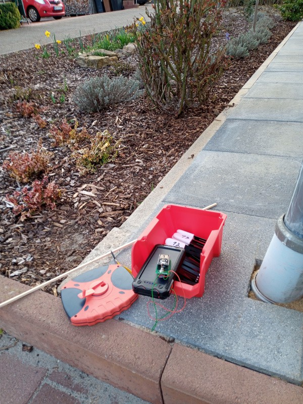
03/28/2021 at 19:24 • 0 commentsI got out in the yard Friday afternoon, late, and set out the sensors.
![]()
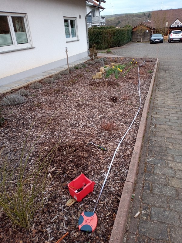
I used a long tape measure and a yard stick to put them in something resembling a regular grid.
![]()
Thereafter followed the better part of two days of cursing and pulling of hair.
The control nodes simply would not work properly.
Sometimes they'd read some sensors and quit. Sometimes they'd read some sensors, reboot, and start over again. Maddening.
The worst part was that they only misbehaved when actually out in the yard. The control nodes can't "see" my yard from the work room, so they'd just time out trying to connect to the sensors. The errors were happening after the connection was made. I couldn't debug the problem because I couldn't reproduce it when the nodes were connected to my computer for debugging.
I tried several things blindly - correcting things that could be mistakes then trying them out.
In the end it was something I didn't do that was the problem, and something I accidentally did while troubleshooting that kept me from finding it.
You have to call "delete" on the Arduino Bluetooth client (BLEClient from the BLEDevice library) after you call "disconnect" on the BLEClient.
It wasn't that hard to figure that out, but while doing other things I managed to accidentally paste a line of code in the wrong place. I wanted to return a nullptr at a particular spot when the Bluetooth service connect failed, and put it in the wrong spot - it always returned a nullptr, even when it worked properly.
I spent much of today trying to figure out how a delete and a try/catch could cause all connection attempts to fail. It can't, of course. I didn't find the mistake until I tried a nearly line by line eyeball comparison of the version on GitHub and the version I was working on.
At any rate, I got it running (the updated software is in the control node repository.)
The first complete run showed that the front yard needed two control nodes rather than just one. The sensors furthest from the control node took forever to connect.
The control node software reports back how many connect attempts it took to reach each sensor. The sensors furthest from the control node hit the maximum (4 tries) and timed out.
I have two nodes out there now. They've gathered data for all 16 sensors on each run every time they've gone through.
While I was trying to fix the problems, I changed the software so that the control nodes can only read a maximum of 30 sensors. From all of the errors, I found that it could easily take an hour to read 30 sensors if every one of them timed out. Since I want to read from the sensors every hour, there's not much point in trying to read more than you can handle (worst case) in an hour. When it all works properly, a node can read 15 sensors in just a few minutes.
The nodes now read all the sensorIDs from the server and put them in an array before reading the sensors. That reduces WiFi traffic while the Bluetooth stuff is going on. It also reduces fragmentation of the memory somewhat.
From a quick look at the raw data, I found a couple of interesting things:
- I'm going to have to buy batteries for the sensors much sooner than expected. Half of the "brand new" batteries in the sensors are reading less than 50% capacity right out of the gate. About 1/3 of the sensors show 100%.
- There's a noticeable temperature gradient across the yard. Something like 3 degrees celsius between warmest and coolest.
- The nutrient content is much more even than I expected - around 200 microsiemens per centimeter conductivity, with a single sensor showing over 300.
- The soil moisture (which is what this project is all about) varies considerably. It ranges from 18% to 51% from different sensors.
Now that I've got good data coming in, I'll get started on the analysis section this week.
--------
I may order some more parts and make a fourth control node. I wanted one in the front yard, one beside the house for the potted roses, and one in the back yard for the wild flowers and the other flowers along the back border. I had to put two in the front yard, leaving me one control node short for the back yard.
-
Quick Update
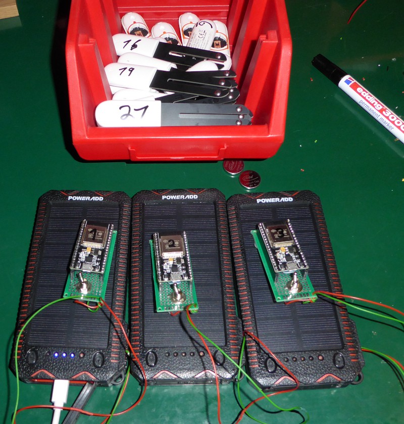
03/25/2021 at 22:18 • 0 commentsI now have all the parts together.
- 21 sensors - I just finished gathering the Bluetooth IDs and marking them so I can tell them apart. I also found one sensor where the LED doesn't work.
- 3 solar powered control nodes.
- 1 Raspberry Pi running the Mud-Py data collection software.
Here's the hardware ready to go out in the yard:![]()
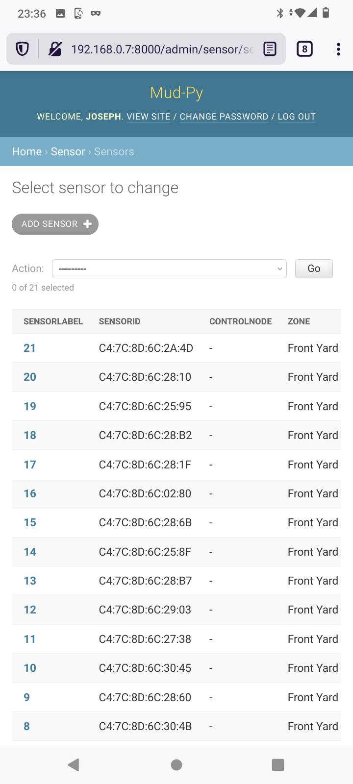
Here's the sensor management page with all the sensors:
![]()
All that's left is to position the sensors in the yard and park the control nodes in their jars - and then write the software to analyze the collected sensor data, of course.
I spent a little time this evening expanding the Mud-Py software to make it capable of a couple of things I KNOW are going to happen.- I'm going to probably have to change the position of some of the sensors - I probably won't get them set right in the yard or I might get them out of place in the map.
- I'll probably have to replace a sensor or two along the way. There'll be 15 of them in the front yard in amongst the flowers, and it is a sure bet that I'll step on one sooner or later.
To handle that kind of stuff, I've made it so that each sensor data entry has a location and the zone the sensor belonged to at the time the measurement was made. Done that way, I can select sensor data by zone and date/time and get a correct set of data no matter if the sensors were moved around.
I am still utterly fascinated by the way Django works with mobile devices.
Here's the sensor list as shown on my phone:
![]()
I didn't have to do a thing to the software at all to get it looking good on the phone. Django just does it right.
-
Mud-Py on a Pi
03/23/2021 at 22:33 • 0 commentsIt has taken me two evenings in a row, but I got the Mud-Py Django site running on my Raspberry Pi.
It was trickier than I expected. I ended up following several tutorials in order to get the Mud-Py site to run under NGINX and to start when the Pi boots.
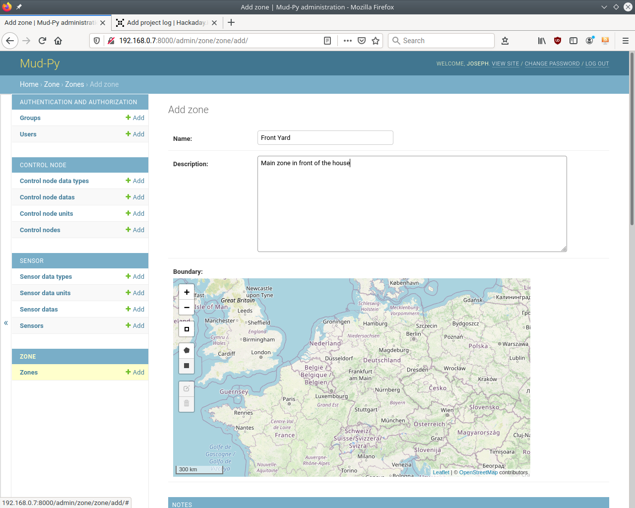
Here's the Mud-Py Zone editor served by the Pi:Yeah, it looks just like the Zone editor served on my computer - but that's what it is supposed to do.
I went ahead and setup the Mud-Py MQTT Bridge as a service on the Py and pointed one of the ESP32 nodes at it.
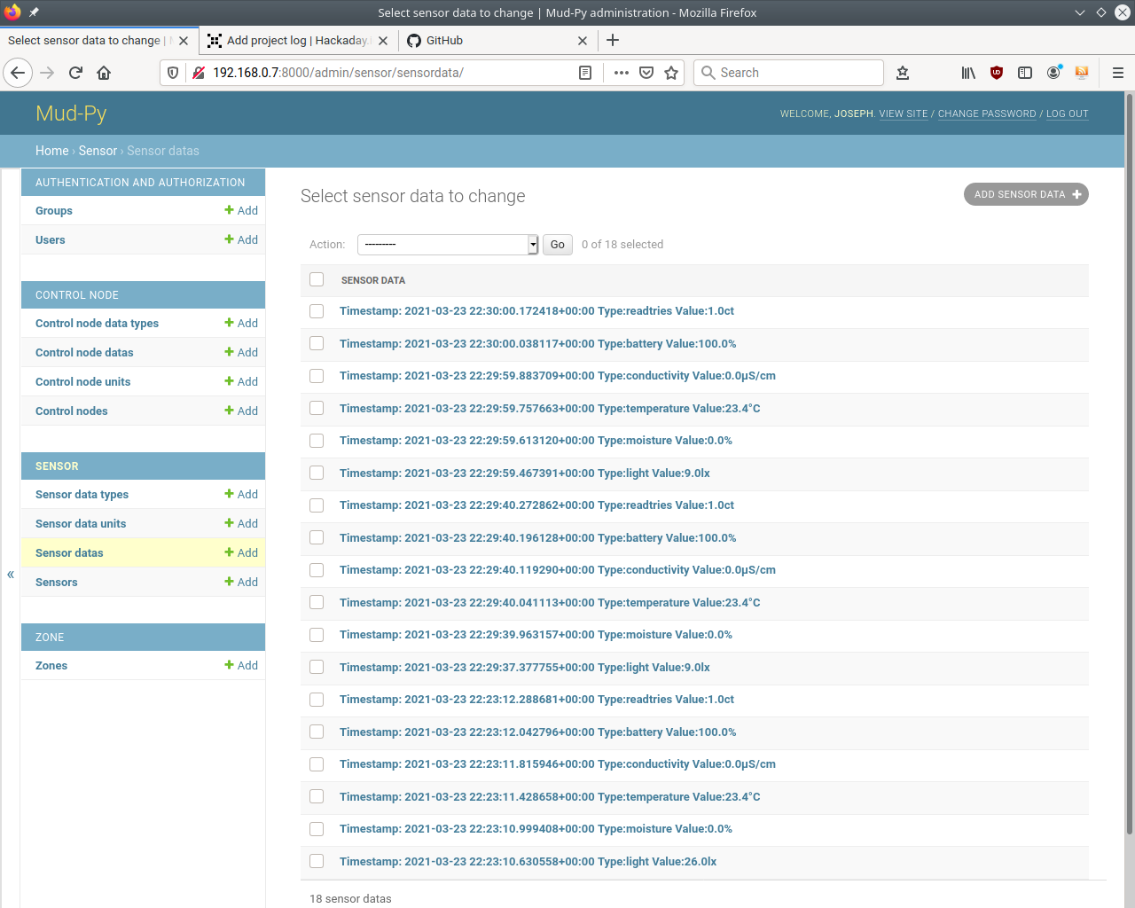
The control node connects, no problem, and reads data from the sensor:Almost there. I've got a few small things to clean up in the software (a configuration file for the bridge) and then get all the sensors and nodes out in the yard.
Documenting how you get all the pieces to play together is going to be FUN (not.) That'll almost be a project by itself. The setup and a list of all the associated libraries will go in a wiki in the Mud-Py GitHub repository. -
More Show and Tell
03/20/2021 at 17:52 • 5 commentsI managed to get a functional version of the ESP32 control node software working this week. I spent several rather intense evenings, flipping back and forth between ESP32 documentation, Arduino documentation, MQTT PubSubClient library documentation, C documentation, and StackOverflow.
The control node works as planned - sort of. I ended up changing plans a bit.The idea has always been for the node to register with the MQTT server and report in. The bridge then sends it a list of all the Bluetooth sensor IDs it should scan. The node then reads them and reports the sensor values back to the bridge. The bridge stores the data in the Mud-Py database. Once the node has done all the sensors, it tells the bridge "done" and the bridge tells it to take a nap for X seconds then check in again.
The outline stayed, but the details changed.
My original concept had the node dropping the WiFi connection while scanning the sensors. I've noticed interference between Bluetooth and WiFi before, and wanted to avoid that.
That would have required the node to store the list of Bluetooth IDs to scan, and also to store the results. That turned out to be more complicated than I thought - memory management is no fun in the Arduino environment.
I ended up leaving WiFi active the whole time, and just doing things "live" - send the sensor IDs one by one as MQTT messages and let the node read and respond to each command as it comes in.
That made a lot of things much simpler, and is the reason I have a functional control node software ready to run.
You can't see bits and bytes, though, so I'm going to show the progress on the hardware side.
I finally got around to buying some hot melt glue to finish up the control node adapter boards and the modifications to the power banks.
Insulated control node adapters:
![]()
I put hot melt glue over the back of the adapter boards. Most of the bare spots back there are connected directly to the battery - I wanted them insulated to avoid accidentally testing the PTC fuses I put in the power banks.
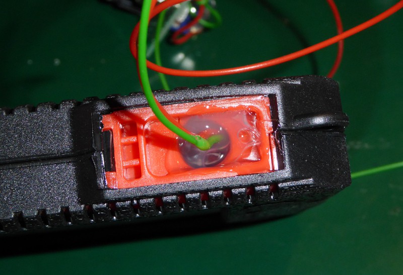
I put some more hot glue in the hole in the power banks where the wires come out. That's more to provide a little strain relief and keep bugs from crawling in and making homes in the power banks.![]()
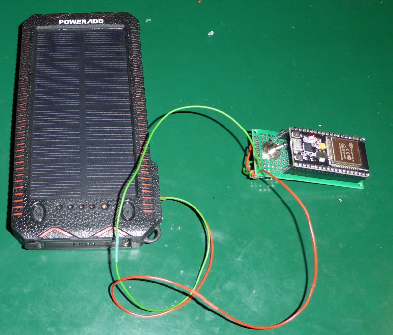
Here's the first completed power bank and a control node doing the first ever battery powered update:
![]()
I also did some preparation for putting the nodes out in the yard.
My original plan was to go full out redneck and just stick the nodes on a post and plop a big, empty soda bottle over the whole shebang to keep off the water.
My wife was not amused by the idea of a soda bottle on a stick in our front yard, so I changed plans.
Lots of people around here put glass decorations (colored globes and what have you) in their yards.
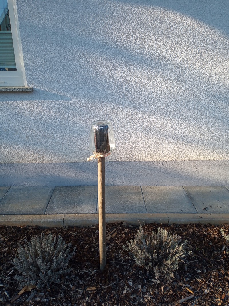
I bought some (cheap) decorative glass jars that will fit over the post and the electronics. The jars look like a (somewhat plain) version of the glass thingies that
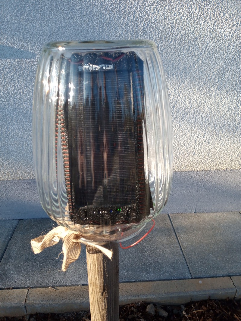
folks use for decorations.Here's the approved "jar on a post" design:
![]()
![]()
The solar cell is charging in there - the green "charge" LED is visible. There's also a blue "progress" LED lit, but it is hard to see.
I think I have all of the pieces together now.
The software is functional. It doesn't have all the features yet, but I can add those in while collecting data.
The hardware is ready. I've got a pile of sensors, and all the stuff it takes to put the nodes outside.
I've got a big pile of sensors stacked up here in my work room.
All that's left is updating the Raspberry Pi with the finished software, and putting all the hardware out in the cold.
I'll do that piece at a time over the next few days.
I have to mark the sensors so that I know which is where, and that'll take a while.
-
Back to Boring
03/17/2021 at 20:21 • 0 commentsI've started on the ESP32 control node software. I'm writing an all new program rather than using the existing MiFlora MQTT bridge as I originally planned.
The changes I'd have needed to make were so massive and invasive that you couldn't have called it the same program any more - I decided I didn't want to try to untangle licensing requirements on something mangled beyond recognition.I have a basic structure set up, with the ESP32 capable of connecting to WLAN and reporting its battery status via MQTT.
I was surprised at how quickly the ESP32 connects to WLAN and then the MQTT server. From reset to the MQTT message arriving at the server takes less than two seconds.I have things set up to use the ESP32 watchdog to reset the ESP32 if something goes wrong. I have it set to trigger if it isn't reset every 60 seconds.
If something gets stuck (WLAN or MQTT server connection right now,) then the ESP32 will go into deep sleep and reboot after 5 minutes.
I've started work on decoding the data from the sensors, but haven't gotten that to a state that I want to commit it to the repository.I don't normally work with C++ or whatever mix of C and C++ the Arduino IDE uses, and I had forgotten how hairy it can be to do things like return an array from a function. That's caused me the stop and rethink the structure I had in mind for the message decoding.
I'm going to sleep on it, and see if I have a better idea tomorrow evening.
I think I'm just going to make a static decoder that just accepts the raw data and has a bunch of methods or properties with the decoded values in them. Maybe two decoders - one for the sensor data, and one for the sensor battery data. The flora sensors have two queries you can make - sensor data and version/battery. A decoder for each query seems like the best bet right now.
-
Show and Tell - Solar Power Adapters
03/14/2021 at 22:34 • 0 commentsI long ago decided that the control nodes would need to be powered from a fairly large battery, that they needed to be solar charged, and that building a solar charging system for a large lithium ion battery was not part of this project.
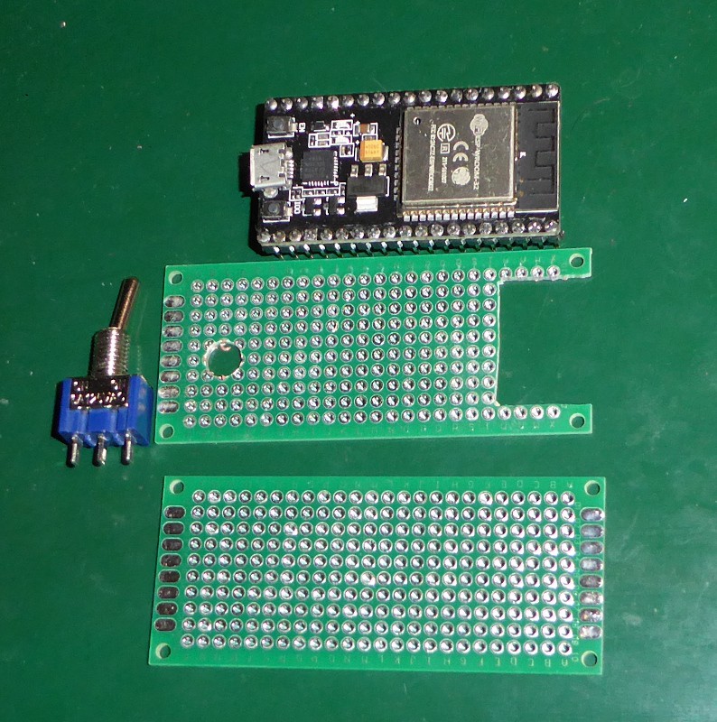
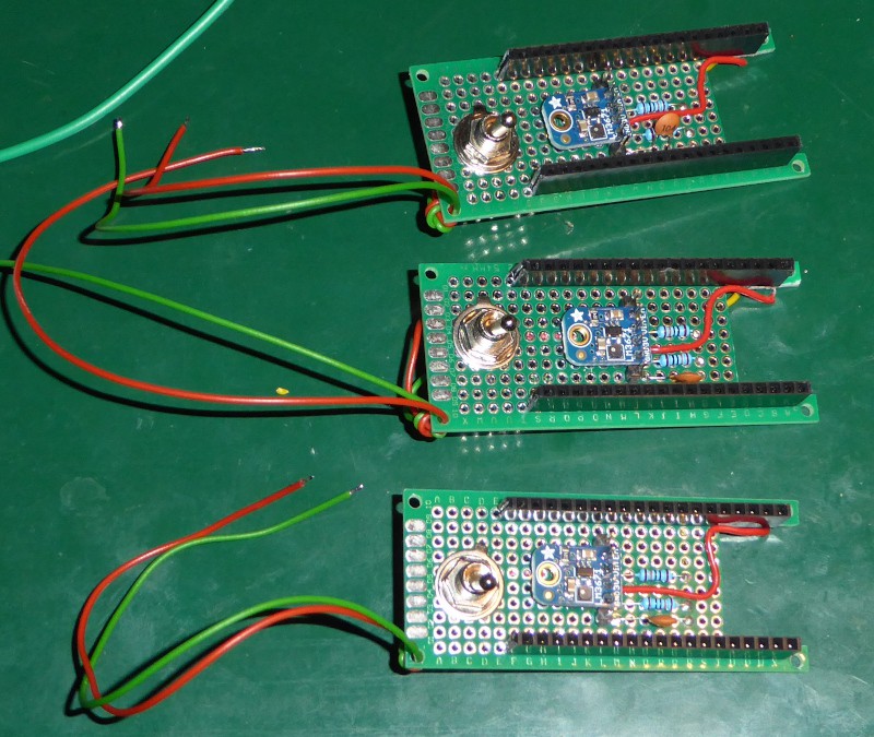
I spent most of my free time this weekend making a set of adapters to hold the ESP32 modules.
Each adapter has an LM3671 buck regulator module, a voltage divider so the ESP32 can monitor the battery voltage, and a switch so I can turn off the power and remove the ESP32 from the adapter.
There's nothing special about them - some perf board, a couple of resistors and a capacitor, a regulator module, and a switch.
One thing I did do, though, was to build them so that I cannot connect the module to a USB cable while it is plugged into the adapter - I'm pretty sure that powering them from the LM3671 and USB at the same time would cause a mess, so I blocked it to keep me from getting stupid ideas.
Most of the last log posts have been rather text heavy. This one will be mostly pictures.
Beginning
The cutout on the right end is to reduce the amount of metal near the ESP32 antenna.
Finished adapters:
With the adapter finished, I attacked the solar charging power banks.
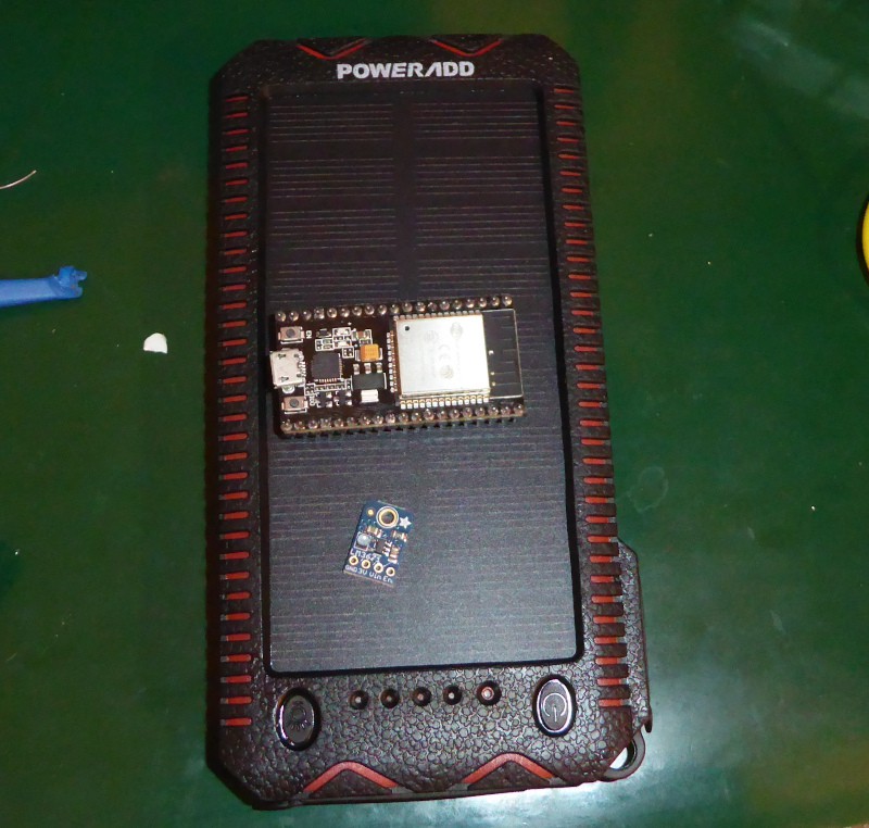
Power bank:
![]()
You may recognize that image if you've been following the logs and my blog.
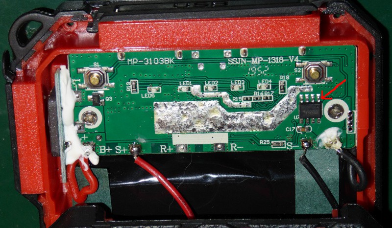
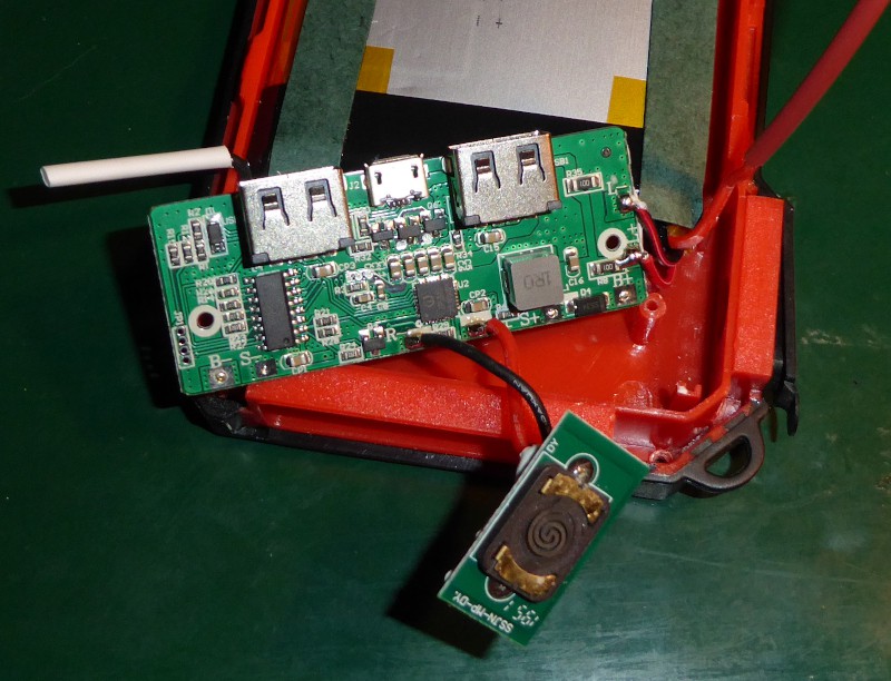
Once you take it apart, you find this:
![]()
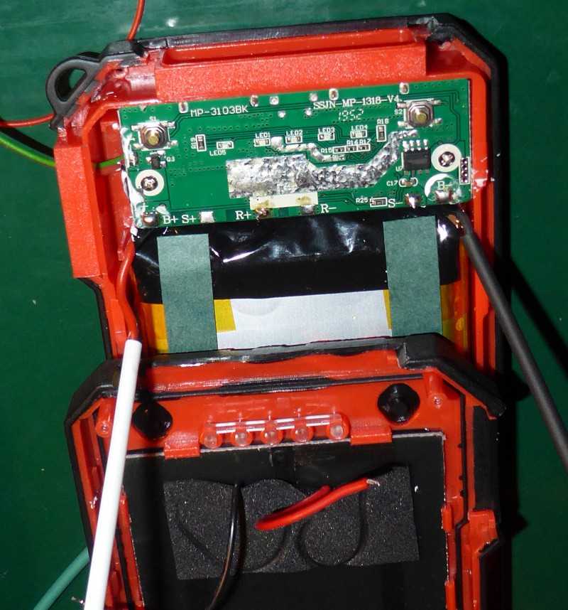
The red arrow points to the XB8886A battery protection IC. If you are modifying a power bank, you need to find the battery protection IC, and make sure that you connect to the correct side of it. You want it to be able to disconnect your additional circuitry as well as the existing circuitry. The XB8886A disconnects the ground. Pins 1,2,3,4 are the "safe" grounds. You connect your load to the battery positive terminal (B+) and to the those pins and the lithium ion cell will be protected from your circuit - that's short circuit and low voltage.
Working on a power bank is like working on the electrical system of car. You always disconnect the ground wire first.
That's the unmarked, thick black wire on the right side. With it disconnected, you can't accidentally short the battery and blow things up.
The battery ground is also the last wire you reconnect.
Since this battery bank is solar powered, the next wire to disconnect is the solar cell negative terminal. That's the black wire marked "S-".
With the grounds disconnected, it is safe to work on the positive wires - there's no place they can cause a short if you bump something.
"R+" is the lighter coil power connection. I removed the lighter coil (the white blob on the left side,) then used the "R+" pad to connect my PTC and the run a wire to the outside for the ESP32.
My PTCs are rated to supply 900 milliamperes continuous, and trip at around 1.5A. That's more than an ESP will need, but still low enough to be safe.
![]()
That's everything disconnected. I'm something of a chicken, so I stuck pieces of heat shrink tubing over the battery wires to prevent accidents.
This is the lighter coil:
![]()
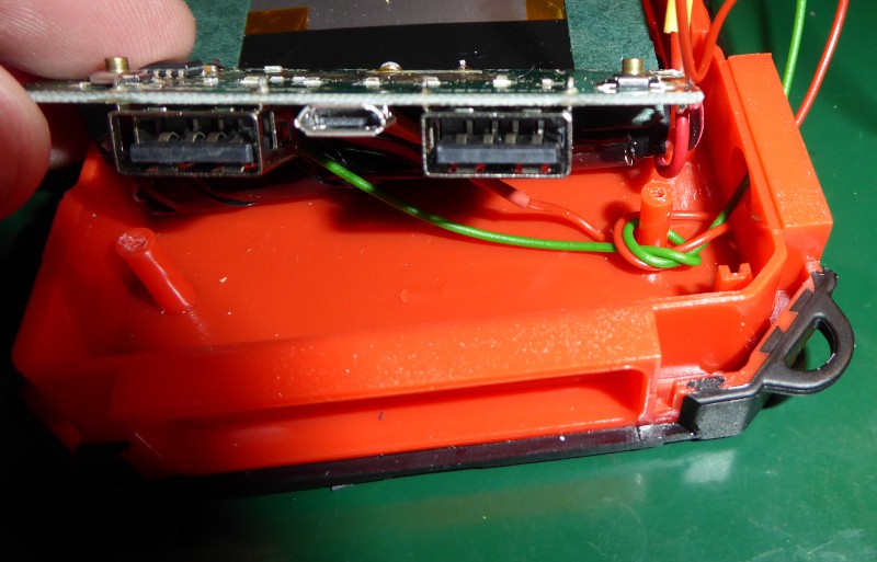
I removed it. My control nodes don't smoke cigarettes, so they don't need lighters - but I do need the hole in the housing to put my wires through.
Here's the PCB with my wires added:
![]()
I've tied the new red and green wires around the screw post to keep them from pulling out, and hot glued the wires in place (not in this picture.) You can't see it, but the red wire connects to a PTC that is soldered to the "R+" pad. The green wire goes to the "S-" pad - that's the solar cell negative terminal. It's on the correct side of the protection circuit and isn't switched.
Modifications complete, ready to be reassembled:
![]()
Again, you do this like you do a car battery: positive terminal first, then ground.
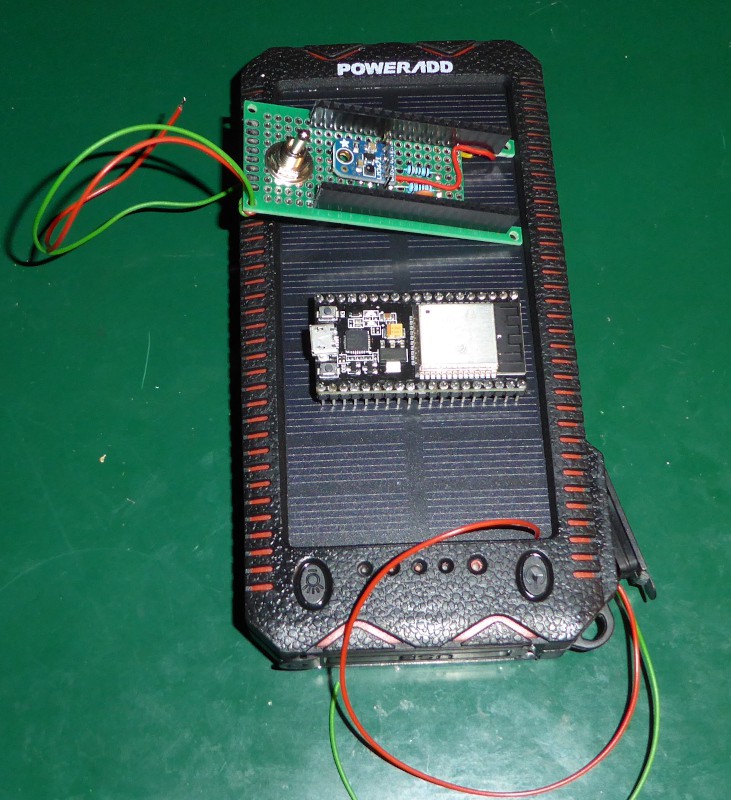
Here's a completed power bank with an ESP32 and an adapter:
![]()
I haven't connected them together. The adapter needs some strategically placed daubs of hot melt glue as insulation on several points, and the lighter port on the power bank needs to be filled as well. I'd have gone ahead and done it, but I've run out of hot melt glue.
I'll start work on the ESP32 software this week, and (with a little luck) be ready to put things out in the yard next weekend.
-
Test run
03/11/2021 at 20:26 • 0 commentsI fired up Mud-Py, the Mud-Py MQTT bridge, and the MQTT server this evening, and turned on an ESP32S programmed with the flora MQTT client software.
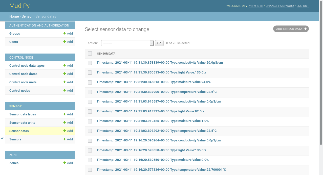
Flora talks to the Xiaomi sensors, and reports the values to the MQTT server. From there, the bridge dumps it into the database, creating sensor objects and other things as needed.Here's the "Sensor data" page with some of the collected values:
![]()
The list isn't very useful as a working tool, but it does show that the bridge is correctly reading the data and putting it in the database. That's adequate for the beginning. It can collect data while I work on the analysis parts of the software.
I'm going to write my own ESP32S software for the control nodes. The flora software works, but it doesn't do the things I need it to do.
I'm going to assemble the power banks for the ESP32S modules this weekend, then start in on the ESP32 software.
-
Building a bridge
03/10/2021 at 22:11 • 0 commentsIt's taken me a few days to get around to writing a new log post, but I haven't been loafing.
I spent some time this past weekend tweaking the Mud-Py models, and wrote up some notes on setting up Mud-Py for development.
I spent more time yesterday twiddling with the hardware - I think I have all the pieces needed to build the nodes, now. That'll get its own write up, when I actually build the darned things.
This evening, I sat down and wrote the MQTT-Mud-Py bridge.
That's about 200 hundred lines of code in two files.
- mud_py_mqtt_client.py - the bridge itself. It connects to the MQTT server, and subscribes to the various messages the nodes can send. It then handles those messages, updating the Mud-Py database and sending responses as needed.
- mud_py_API.py - a collection of functions for putting data into the Mud-Py database. It handles the somewhat squirrely looking task of accessing the Mud-Py Django classes, and adds some functions for automatically creating certain base data as well as automatically creating new nodes and sensors as needed.
I'm not done yet, but most of it is there.
The idea is for each node to connect to the MQTT server, then send an announcement (topic = "node/<nodeID>/battery" value=<battery voltage>.)
The bridge then creates the node if it isn't there, then it inserts the battery voltage in the node data table.
It then puts together a list of sensors that the node should query, and sends it to the node (topic = "node/<nodeID>/sensors", value = <list of sensor IDs>.)
The node then queries all the sensors, and sends sensor messages (topic = "sensor/<sensorID>/<sensor type>", value= <numerical value>) through the MQTT server.
The bridge picks up the sensor messages, and updates the sensor data table, creating base data (sensor types, value types, and value units) as needed.
Once the node has sent all of its sensor data, it sends a "I'm done" message (topic = "node/<nodeID>/done", value = <not used>.) In response to the "I'm done," the bridge sends a "sleep" message (topic = "node/<nodeID>/sleep" value = <time to sleep in seconds>) back.
The "sleep" time is calculated for the node to wake up at the start of the next hour. The nodes don't have a real time clock. They'll just set a wakeup time based on the number of seconds, then go into a deep sleep mode.
When the node wakes up, it goes through the same procedure.
While writing this up, I realized that I forgot to implement the sensor list response. I got so involved in the "automatically creating base data" part that I forgot to generate that response.
I guess that gives me something to do tomorrow, since I plan to leave the nodes to the weekend. I have some cutting and drilling to do to build the nodes, and I'd rather do that on a Saturday afternoon.
To test the bridge, I wrote two little scripts to send simulated node and sensor messages. They are in the "Simulations" folder.
I also whipped up a really simple MQTT snooper. It subscribes to all messages, and prints them out so that I can see what's going on.
No pictures this time around - there's not much interesting to see when a command line program shuffles data.
I went back in and implemented the sensors list response. It aggravated me that I forgot it. It took a little over half an hour.
Soil moisture monitoring in a flower garden
When do your flowers have enough water, and how do you know?
 Joseph Eoff
 Line chart:
 I did say they were rough sketches.

 Yeah, it looks just like the Zone editor served on my computer - but that's what it is supposed to do.
 Almost there. I've got a few small things to clean up in the software (a configuration file for the bridge) and then get all the sensors and nodes out in the yard.
