Close
0%
0%

Mothra: Acoustics Laboratory on a Stick

STM32WB55 host with microphones and accelerometers and lots of memory for vibration and sound analysis

Similar projects worth following
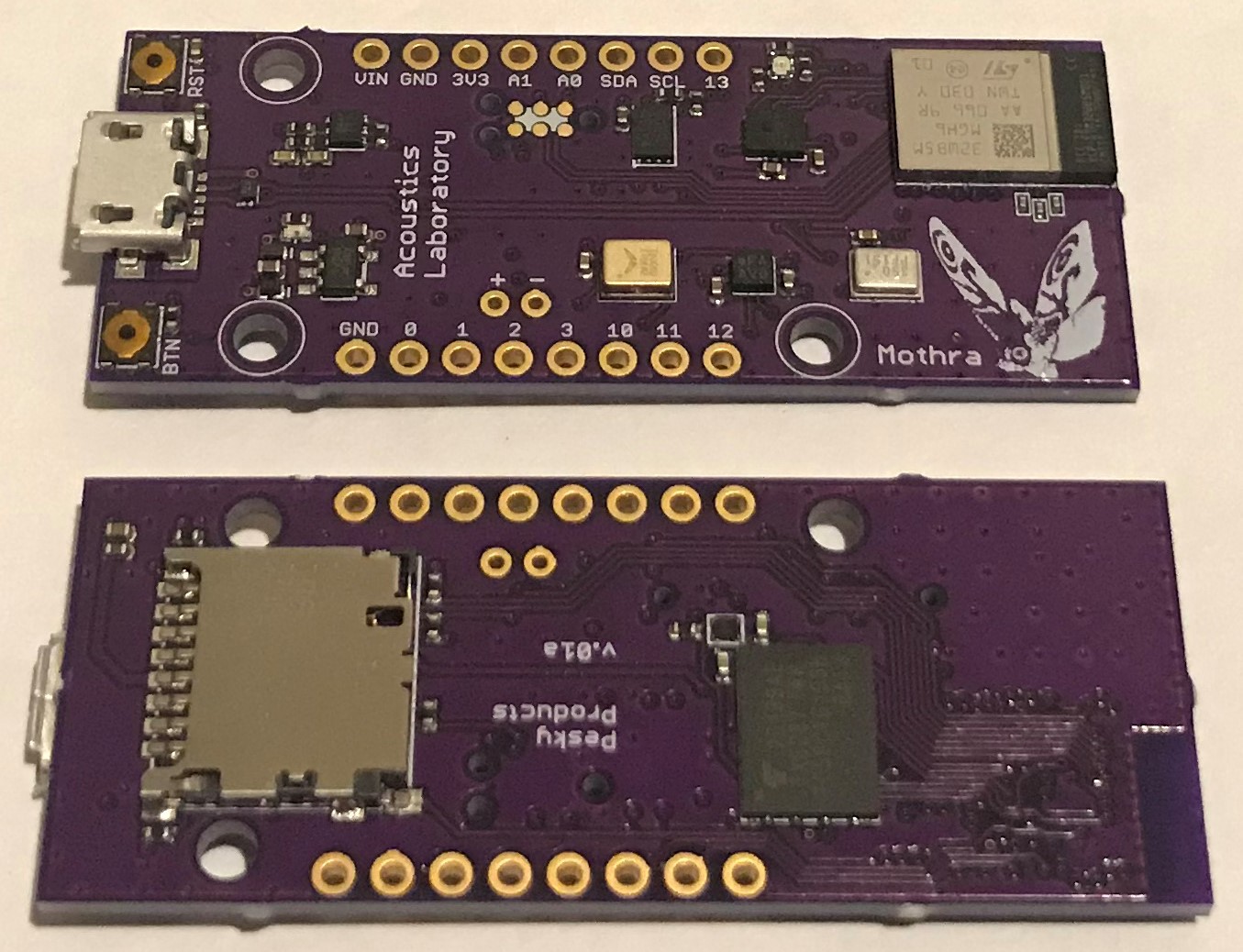
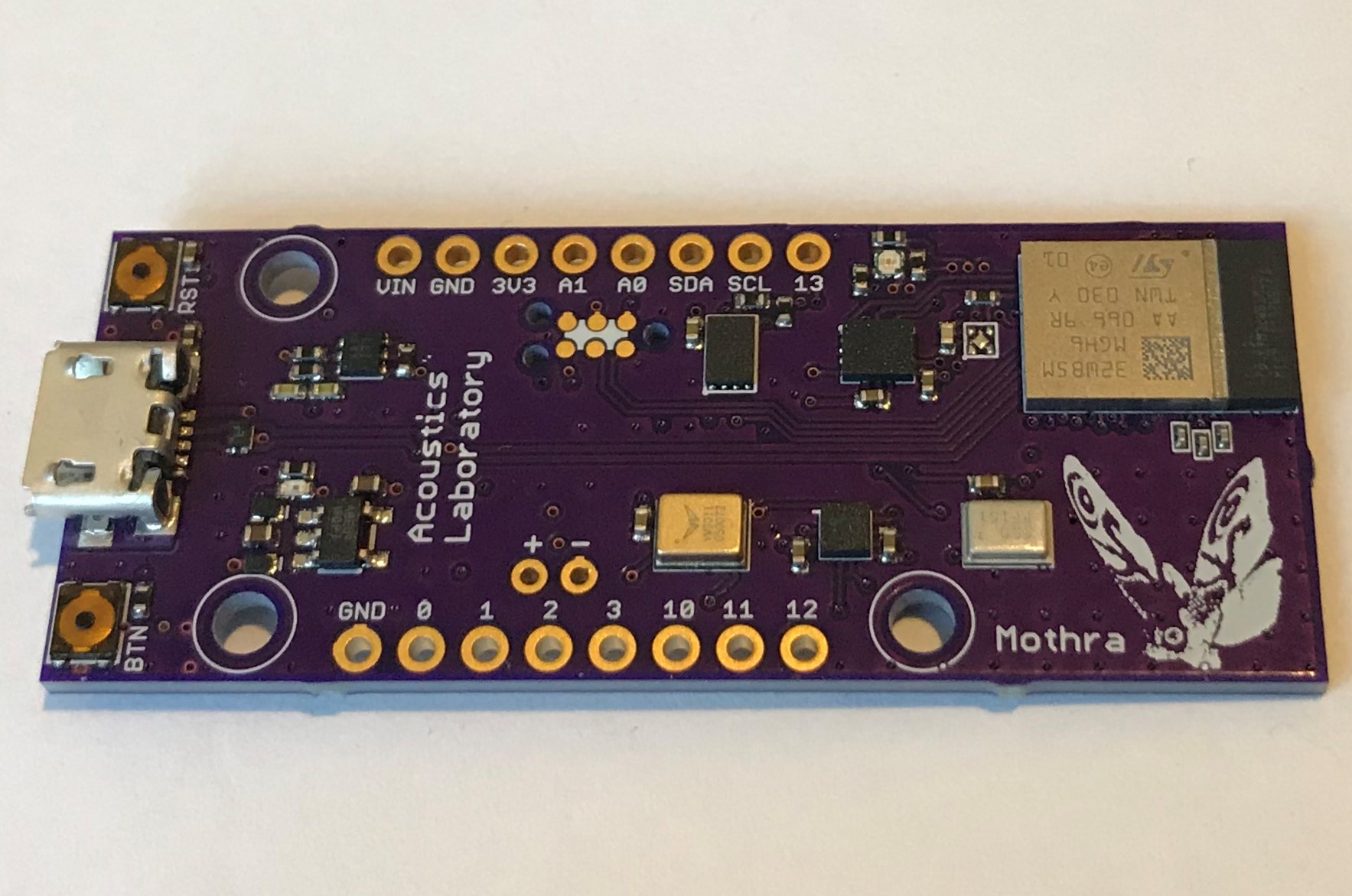
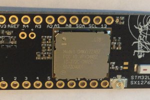
The new STM32WB5MMG module comes with 1 MByte flash and 256 kByte of SRAM as well as embedded BLE with 75 meter range. It also has 68 GPIOs; plenty to connect an SD card, QSPI NAND flash as well as a high-band-width SPI accelerometer and ultrasound PDM microphone. Still more: ultra-low-power wake-on-motion accel and wake-on-sound microphone. We have combined these ingredients onto a small pcb for vibration and audio analysis experiments. Acoustics laboratory on a stick.

There are a lot of moving parts to this project so I will describe the ingredients one at a time and then put them together at the end.

 1)  We have been working to exploit ST's new line of BLE-enabled STM32WB MCUs. We have developed a power- and memory-efficient Arduino core for several hardware designs including the Firefly development board and the Katydid wearable sensor board.

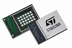
The STM32WB is a dual core MCU with a 32 MHz  Cortex M0+ managing the BLE stack and a 64 MHz Cortex M4F for application programs. The STM32WB55 variant sports 1 MByte of flash memory and 256 kByte of SRAM and now is available as a 7.3 mm x 11 mm module for easier integration into embedded designs. The module also has 68 GPIOs available, making it perfect for designs that have a lot of serial peripherals. 

2)  We have been testing ST's new IIS3DWB ultra-wide-bandwidth, low-noise 3-axis digital vibration sensor  (accelerometer). The SPI sensor has a bandwidth of 6.3 kHz at +/- 3dB, a data rate of 26.7 kHz, a noise figure as good as the LSM6DSM (75 ug/SQRT(Hz)) and uses just 1.1 mA running full blast. We have been testing this sensor using the Dragonfly development board which has a STM32L476 MCU with Cortex M4F running at 80 Mhz, so a close analog to the STM32WB55. We have been getting very good results so far in terms of data rate and FFT speed and accuracy. You can read more about our tests to date here.

3) TDK (Invensense) has a line of PDM microphones that extend into the ultrasonic range. The ICS41350 measures sound from ~100 Hz up to 40 kHz. The ICS41352 from 100 Hz up to 85 kHz. The STM32WB55 has some hardware PDM filtering capability but for efficient analysis there is quite a bit of arcane and complex software filtering required to extract the best signal quality especially in the ultrasound ranges. We are selling breakout boards for these mics at Tindie and it is straightforward to record high-fidelity audio at 16 kHz and play it back via, say, Audacity using the Firefly development board. The challenge here is to extend this ease-of-use and fidelity to the ultrasound range.  

4)  Mothra is designed to be an ultra-low-power device. We have taken pains to choose components and strategies to keep power usage under strict control. For example, we are using a GPIO to power the ICS41350 to cut its otherwise ~12 uA sleep current to zero. We have an LDO controlling power to the NAND flash saving ~30 uA in sleep mode. This is a general feature of our designs and critical to any real application of the technology. In most cases, we expect derivatives of the Mothra device will be battery powered and remotely fielded with battery lifetime a key consideration. With this low power focus in mind, we have included Wake-on-Motion and Wake-on-Sound sensors on the board.

The BMA400 is a small, 12-bit, 3-axis accelerometer with an ultra-low-power mode using 800 nA running at 25 Hz and able to wake an MCU host via interrupt when motion is detected. In this mode, the interrupt engine is limited to simple threshold crossing on one, two, or all three axes with some configurable hysteresis. However, in normal mode, with access to more sophisticated built-in interrupt detection like step detect, tap and double-tap detect, orientation change detect, etc the BMA400 can still run at 12.5 or 25 Hz and use just 3 - 4  uA. The BMA400 can be used to detect vibrations and wake the system for fuller analysis and then detect a "no motion" condition allowing the system to go back to sleep.

The VM3011 is a new PDM microphone that embeds a wake-on-sound capability configurable by the user via I2C. The VM3011 remains in a low-power mode that uses ~10.5 uA and when the ambient noise background exceeds a user-defined threshold the microphone wakes in less than 200 us, sends an interrupt to the MCU host, and allows the system to wake to record and/or analyze the sound.

... Read more »

  • Second assembly and testing

    Kris Winer03/22/2021 at 04:20 0 comments

    03/21/2021

    Got the revised pcbs back from OSH Park and put a couple together today.

    Happy to say no shorts or design errors....yet.

    Thomas Roell provided a preliminary Arduino core for testing the boards. I was able to blink the three RGB leds, read MCU temperature, and read battery voltage. I found all three I2C sensors on the internal I2C bus and was able to get the BMA400 to wake on motion and sleep on no motion. I verified I could record the sound of my voice using the ICS41350 PDM microphone. I verified BLE Tx using the Nordic UART service.

    The RSSI of the module was around -50 dB when close to the smartphone. This is a little bit worse than what I have measured using the Firefly with the discrete STM32WB55 and its pcb antenna, which was somewhat surprising.

    We have some more software development before we can test the IIS3DWB. And for some reason I wasn't able to get the SD card to work yet. Still, for one day's worth of assembly and testing the design seems to be working about as well as can be expected.

    I ran a simple blink sketch with the MCU put into STOP mode for five seconds at the end of the main loop and used an ST power meter to check power consumption. The Mothra device is using ~210 uA in STOP mode, where it really should be using ~20 uA. So somewhat of a mystery here as to what is causing the extra 10x power usage in low power mode.  

    Early days, still a bit of work to do before we can start using the device as intended...

  • First Assembly

    Kris Winer03/12/2021 at 22:36 0 comments

    03/08/2021 

    It's always fun to get the first boards from OSH park and spend some time assembling them. This is when you find out what dumb mistakes were made in haste. And of course, after putting two of the Mothra.v01 pcbs together, I discovered that I had swapped VDD and GND when connecting the power-control LDO to the NAND flash. 

    I had to remove the LDO to avoid the resultant short. This means that every component on the first version except the NAND flash should work as designed or at least be testable.

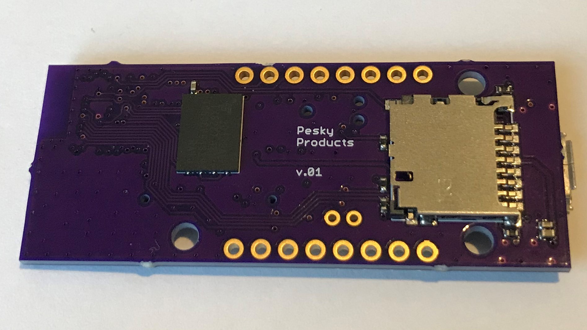
    You can see the trace fanout on the bottom layer for the QSPI IIS3DWB and SPI SD Card et al. The design rules "require" that all traces route out of the bottom of the module such that the area to the right (in the above image of the board bottom, the area bottom left) of the module remain free of components and signals and be covered with ground plane and vias. This makes the trace traffic mighty congested even on a four-layer pcb; the second and third layers look about the same as the bottom one.

    The STM32WB5MMG module embeds a STM32WB55VG 100-pin WLCSP and there are 85 total pins in the small 7.3 mm x 11 mm module.

    I was worried that the 0.435 pitch pins on the periphery might be hard to solder. However, I found it was surprisingly easy using my usual 26 gauge syringe with low-temperature solder paste and a combo quartz heater plate and hot air gun.

    This was my first experience using 0201 passive components. Three sensitive pins require 3.3 nF filter capacitors near the module, which are recommended to be 0201 (or smaller!)  Somewhat to my surprise, these were as easy to use as  the 0402 passives I regularly use.  I am tempted to start using this package size more often, especially in very small designs.

    I remember when I ordered some 0201 caps by mistake years ago (I still have them) and thought "there is no way I could ever make use of these!". What seemed impossible then will become a matter of course soon enough...

    The fix to the botched circuit was easy to affect and we should have Mothra.v01a pcbs available soon. In the meantime, we are testing what we can using the wounded boards.

View all 2 project logs

Enjoy this project?

Share

Discussions

Thomas Roell wrote 04/03/2021 at 21:05 point

Ok, finally the arduino core is up there and running:

https://github.com/GrumpyOldPizza/ArduinoCore-stm32wb

NAND flash is not working ... of course. Something always goes south. Have not gotten the SDCARD detect pin to work properly either, so this is disabled for now (i.e. it always tries to read the card). 

A couple of things ... because I am ticked off that SD_DETECT does not work ... so as therapy a few lines ...

This board is kind of a tad out there.  It has 10 usable GPIOs. On there LPUART, which can in theory go up to 921600 baud. Full RTS/CTS support. For inquisitive minds, yes there is XON/XOFF as well. There is a master/slave I2C port, and a SPI port. So nothing special ... except that, yes the SDCARD is on it's own SPI. And yup all the internal sensors are on their own I2C bus, so that they are shielded from any screwups on the header pins.

The interesting part starts now with IIS3DWB. Everybody who looked at the STM32WB datasheet knows that this part has only 2 SPI ports, which are already spoken for. So what Mothra does is to put IIS3DWB onto USART1 and abuses it as SPI port. 8MHz CLK, full async DMA supported. That means a bandwidth of about 800kB/sec. IIS3DWB needs about 190kB/sec. So that was a tad involved to do. Net result is that it's possible to read IIS3DWB while being able to read/write to the SDCARD at full speed.

  Are you sure? yes | no

Kris Winer wrote 04/04/2021 at 01:22 point

Just by way of confirmation, I tested IIS3DWB function on three of the Mothra boards and happily all are working. Typical FIFO read time of 512 data samples is 4.7 msec = 770 kB/sec; theoretical speed is 512 samples x 7 bytes/sample x 8 bits/byte)/8 MHz = 3.6 msec.

Time for 512 channel x 25 Hz bin width  (6300 Hz flat bandwidth)  FFT is just under 1 msec at 64 MHz CPU clock speed. 

The 26.7 kHz IIS3DWB data sample rate means 512 samples are ready for FIFO read every 19 msec, leaving lots of head room for higher FFT resolution. For example, we know from previous work (see Github) that 2048 FFT bins would take ~5.0 msec (5 x 1 msec, Nlog2(N)). We could probably safely work at even 4096 bins (~1.5 Hz resolution) requiring ~11 msec, although this might be pushing it.

  Are you sure? yes | no

[deleted]

[this comment has been deleted]

Kris Winer wrote 03/16/2021 at 02:43 point

Will do. We intend to regularly update via logs as we learn how to use this beast.

  Are you sure? yes | no

Kris Winer wrote 03/14/2021 at 04:37 point

Not sure what "it" is but surely there is room for more than one Acoustics Laboratories on a Stick! Are details of your project available?  

  Are you sure? yes | no

AVR wrote 03/14/2021 at 22:41 point

it being a baord based around this new STM32 2G module, I released a footprint library 3 weeks ago and designed a feather baord based on it, protoing soon.

  Are you sure? yes | no

AVR wrote 03/14/2021 at 04:31 point

hmmm you beat me to it, mine is heading to the fab, I am focusing on porting Apple Homekit, CircuitPython, and getting some RTOS that supports Thread on to it. Gonna be mass produced too.

  Are you sure? yes | no

Thomas Roell wrote 04/03/2021 at 21:07 point

loadKiCAD, just for fun, check out this here:

https://github.com/GrumpyOldPizza/ArduinoCore-stm32wb/blob/master/system/STM32WBxx/Source/armv7m_rtos.c

... some RTOS ...

  Are you sure? yes | no

Similar Projects

Does this project spark your interest?

Become a member to follow this project and never miss any updates