Close
0%
0%

Wall SCARA

Fold-up wall-mounted 3D printer using a SCARA robot arm

Similar projects worth following
This printer is designed to be compact, affordable, and able to print very tall things if you want it to (up to 1070mm on mine). Based around a 2x4 board, two cheap SBR12 rails, and a T8x2 leadscrew. One rail sticks up to act as the shoulder axis, guaranteeing perpendicularity to the Z axis. The bed is 300x200mm, which is almost entirely reachable by the 270mm arm. You can use a wider bed to cover more of the SCARA envelope.

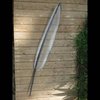
The bed is angled at 25 degrees to provide room for the elbow to not run into the wall. It folds down on a hinge when not in use, protruding a mere 11cm from the wall. The arm can either be stretched out flat along the wall, or folded up in which case it protrudes about 15cm.

Most of the parts are designed to be printed with a 1mm nozzle to reduce print time. Around 700g total filament used.

I'll get all the files and instructions posted eventually, but may need some redesign to increase reduction ratio/resolution.

Arm segment lengths: Both 135mm
Shoulder range: -40 to +125 degrees
Elbow range: 0 to 159 degrees
Angle 0 points toward positive X. Positive angles turn counterclockwise. If shoulder angle and elbow angle are 90, then the shoulder axis, elbow axis, and nozzle all lie on the Y axis (centerline of the bed).

Arm uses GT2 timing belts and pulleys. Shoulder reduction is 7.5:1, elbow is 5.625:1.
Shoulder: Single stage, pulleys 16:120, belt 280mm, center distance 63.10mm
Elbow motor to second stage: Pulleys 16:60, belt 200mm, center distance 60.37mm
Second stage to elbow: Pulleys 40:60, belt 400mm, center distance without idler 149.86mm, with 65T idler 135mm

The bed is rotated 25 degrees around the vertical axis to allow the printer to be very low-profile while having room for the elbow to not run into the wall. Can be a bit confusing since there are essentially two coordinate systems being used in the physical design; one relative to the wall and one relative to the bed. Though from the software side, the bed coordinate system is all that matters.

Bed dimensions are nominally 300x200mm, though the arm can't quite reach the two outer corners. The unreachable areas are approximately triangular, 50mmx25mm on a 300x200mm bed, or 50x50mm on a 350x200mm bed. The bed width can be up to 450mm, though anything over 300mm has an unusable area at the bottom left corner because the end of the arm runs into the wall. Also noteworthy is that the printer can be self-replicating if you use a 300x215mm bed. The extra length isn't that useful most of the time since it can only be reached near the middle, but BedTop.stl can't be printed without it.

The near edge of the bed should typically be 50mm from the shoulder axis center (the minimum reachable radius for the arm)

The printer is designed for Creality style hotend and extruder and 4010 fan. It has an integrated mount for Petsfang Bullseye part cooling duct (https://www.thingiverse.com/thing:2759439), which takes a 4010 centrifugal blower. If you want to use a different hotend, the end of the arm can be modified as necessary to mount it. If possible, keep the nozzle in the same place. Otherwise the effective arm length and/or max elbow angle will be changed.

The arm uses sensorless homing, and Z axis uses an optical endstop.

I took some measurements to see how much everything deflects with weight on the bed.
Leadscrew deflection: Rail carriage drops 0.1mm per kg of mass placed on the bed.
Bed deflection: Center of bed drops 0.3mm per kg of mass evenly distributed on the bed. Subtracting carriage deflection, this is 0.2mm due to combined bed support spring compression and tilting of the bed (rotating around the hinge). This works out to a maximum of .115 degrees of tilt per kg.

WallSCARA-preview.blend

This contains most of the printed parts. I'll upload a complete version later, along with BOM and instructions.

blend - 7.92 MB - 03/18/2021 at 12:51

Download

  • Not dead

    dekutree6404/21/2021 at 08:04 0 comments

    For what it's worth, I have still been working on this intermittently, but still not finished.

    I bought some 0.9 degree steppers, which improved the ripples even further.

    Calibration gave me a hard time, but I've got it all worked out now so you just take 3 measurements with calipers (shoulder to elbow distance, elbow to nozzle distance, and shoulder to nozzle distance while in home position) and type them into the firmware configuration.

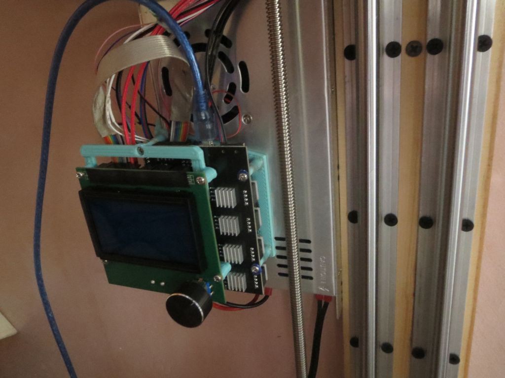
    I added an LCD controller. I had originally planned to run tethered to the computer because I was too cheap to buy one, but it really is nice to have, and can still run tethered too.

    I learned a nice new technique from Dan Royer's youtube channel, called crush ribs. Basically instead of trying to make round holes that perfectly match the diameter of bearings, you make them oversize but with a few protrusions that actually make contact with the bearing. It allows things to flex a bit to compensate for the low precision of 3D printing, and works much better than the horizontal ridges used in the Blender model I posted before (which do help, but still often require a lot of fiddling to get a good fit).

    But there's one insurmountable design problem, which is that the elbow belt tension flexes the arm enough that the shoulder and elbow axes are significantly out of parallel. The reason I made the arm fairly thick in the Z direction was precisely to prevent this problem, but it seems plastic is just too flexible. I got my printer working by trial-and-error shifting the bearing hole positions by a small amount until the axes are reasonably parallel under tension, but it's not a good solution. Even after a lot of effort it's not as precise as I'd like. I've thought of several options to deal with it, but I don't especially like any of them:

    1. Add an adjustable counterbalance tension device toward the bottom of the arm (e.g. a threaded rod or a length of heavy fishing line or thin steel cable), so after tensioning the belt, you can adjust a screw until the axes are parallel.

    2. Make one of the shoulder or elbow bearings movable so you can trial-and-error it more easily than what I did.

    3. Build in a tilt to the axes, and use the belt tension itself to fine-tune them parallel.

    4. Major redesign so the elbow pulley is down in the middle of the arm instead of cantilevered on top, so the tension is supported on both sides.

    5. Use a different elbow gearing mechanism that doesn't put tension on the arm in the first place.

    1-3 don't address the problem of belt tension varying with force from the motor, but at least with my current acceleration rates it doesn't seem to be a problem anyway. I don't have any ideas on how to accomplish 4, so I think I'll give 5 a try first, using a round NEMA14 motor mounted on the elbow joint with either a compound planetary or harmonic reducer integrated into the elbow.

  • Goodbye pancake

    dekutree6403/18/2021 at 11:43 0 comments

    Aha, so the elbow pancake stepper was the cause of my print quality issues. Apparently it doesn't hold microstep positions as well as the larger ones, causing major ringing artifacts as the arm is able to vibrate between the two full step positions. I tried increasing the current, but it didn't seem to have any effect.

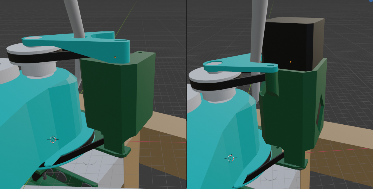
    I redesigned the motor tower to hold a second 34mm up on top, which is not quite as elegant as the old design, but actually a bit nicer functionally because it provides a place to trap the bowden tube/wires without having to pass through a hole in the top bracket (which is a major pain if you ever need to pull them back out). I also added a window to improve cooling (diamond shaped to allow printing without supports).

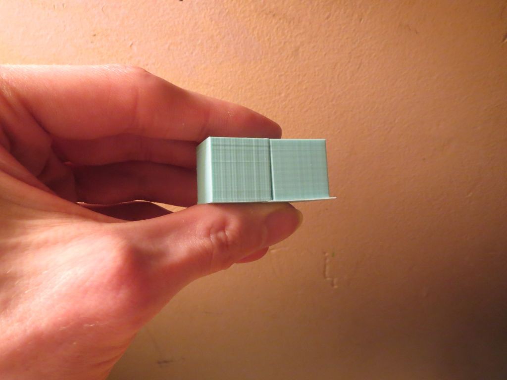
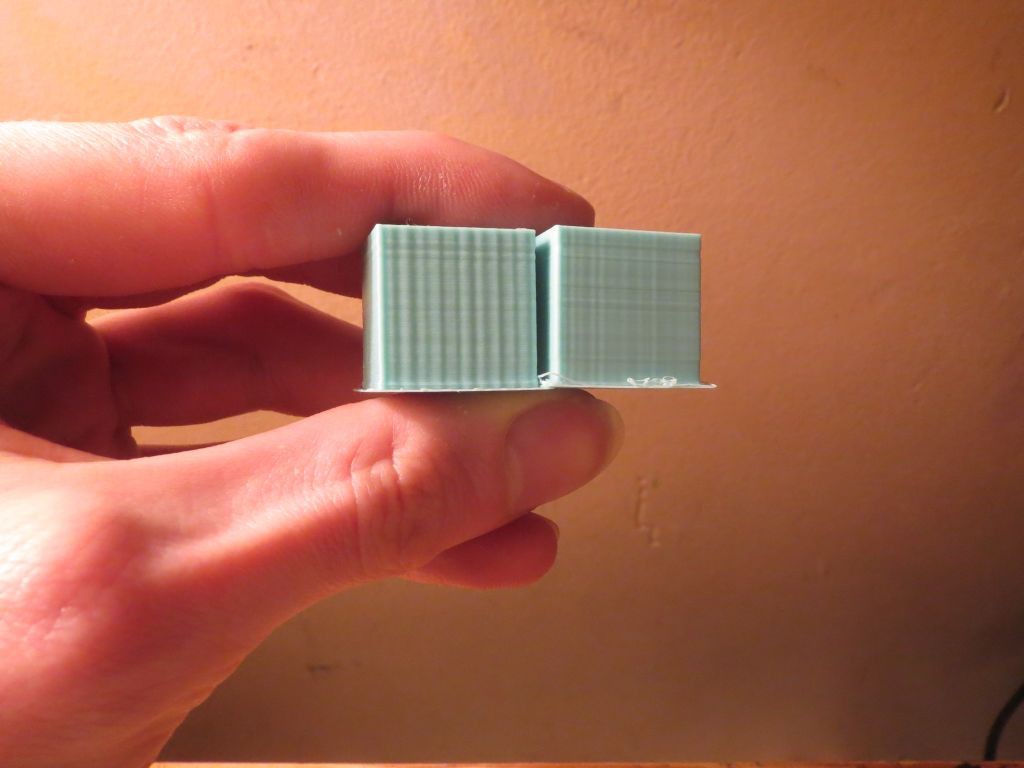
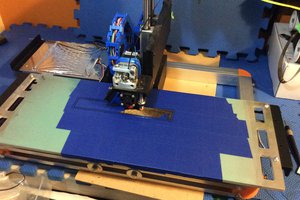
    The photos show before and after of 20mm/s and 60mm/s print speeds. Ripples are much smaller now, especially at high speed.

View all 2 project logs

Enjoy this project?

Share

Discussions

Mike Hjorleifsson wrote 03/17/2021 at 16:23 point

Can you provide more details would love to do a 2020 extrusion variant

  Are you sure? yes | no

dekutree64 wrote 03/18/2021 at 12:47 point

Working on it. 1.5x3" rectangular bar would work best, if you're willing to drill and tap a lot of holes.

20-4080 may work, but the slot spacing is not quite right for the mounting holes of SBR12 rails, which are 22mm apart. You could make it with m3 screws, but you couldn't use normal T nuts that center in the slots. Also the SBR12 blocks are 41mm wide, so you'll either need to sand them a little narrower to allow having two side-by-side on rails spaced at 40mm, or stagger them (two on the left rail, one on the right) so they don't need to fit side-by-side. You'll also need to make a solid aluminum top plate (1/8" would probably be thick enough) because there are a couple screws into the endgrain of the 2x4 that aren't aligned to screwable spots in the extrusion.

I'll go ahead and upload the current Blender model if you want to have at it before I finish writing instructions.

  Are you sure? yes | no

Mike Hjorleifsson wrote 03/18/2021 at 13:26 point

Thanks i will check it out

  Are you sure? yes | no

Dan Maloney wrote 03/15/2021 at 18:43 point

Interesting idea to mount it on the wall. What benefits does this have over just doing a benchtop printer? I'd imagine stability would be greater, but that's just a guess.

  Are you sure? yes | no

dekutree64 wrote 03/15/2021 at 20:01 point

Yeah, the wall studs are supported at both top and bottom, so it should be a lot less wobbly than screwing the bottom end to a table or floor. But mostly it's about space conservation. It wouldn't make much difference for a print farm, but I don't use it every day so being able to fold up out of the way is really nice.

  Are you sure? yes | no

Similar Projects

Does this project spark your interest?

Become a member to follow this project and never miss any updates