-
Test Drive: What Makes It Run?
11/11/2021 at 06:56 • 0 commentsAfter assembling the car, it is now ready for testing. The goal of the test is to calibrate the car for it to stay on this ring track.
![Triode Car - Ring Track Triode Car - Ring Track]()
On the initial run, the car may struggle to stay on track. This is due to the brightness of the environment causing the photoresistors to receive inconsistent values, further making the motors function at the wrong time.
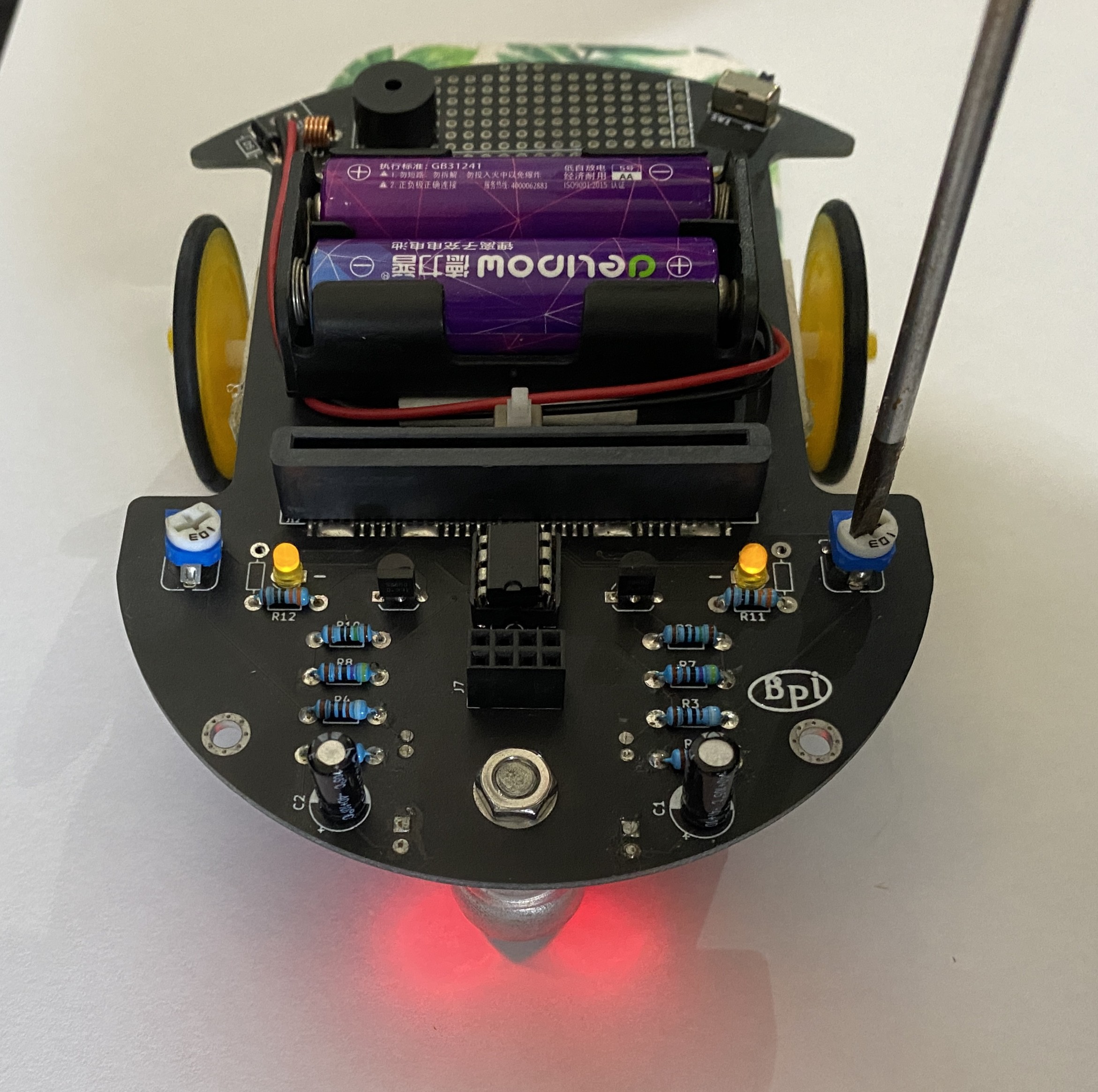
To fix this, I placed the car on a blank piece of paper and adjusted both potentiometers manually. Once it reaches the point where the two motor indicators seemingly light up simultaneously, this shows the car has been calibrated for the current environment.
![]()
test run number two, results show the chances of it running off course have reduced drastically, although it's still wobbling.
The theory of the line-tracking feature is fairly simple. The car is equipped with an LM393 microchip controller to control the motors. The photoresistors act like a switch, when the resistor hovers above the dark line, its resistance value changes due to dark surfaces reflecting less light, and it is that change that helps the microchip determine whether it is on track or not.
Therefore, in the standard mode, the microchip can only drive one motor at a time, making it wobble on the track. The wobbling issue can be solved later when we get to learn to implement a software fix.
The car is now relatively stable, but there is still a small chance of it running off course. This is due to the hardware limitations of the photoresistor, although it seemed to instantly react to the brightness change, it actually has a 20ms reaction time. Think of it as it updates the resistance every 20ms. What impact does this have? Well, the car may fail to react during the slight interval, causing it to run off course, although it is very unlikely. I'll try to bypass this using a software fix later on when we get to control it using the micro: bit.
-
Know Your Part(s)!
03/29/2021 at 06:19 • 0 commentsThis is the first part of assembling the Triode Car.
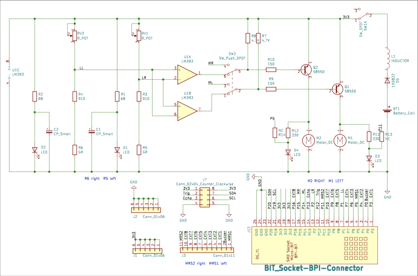
We will be introducing the parts used on the Triode Car and how to install them onto the circuit board with the help of schematics.
![]()
(Photo of the schematics)
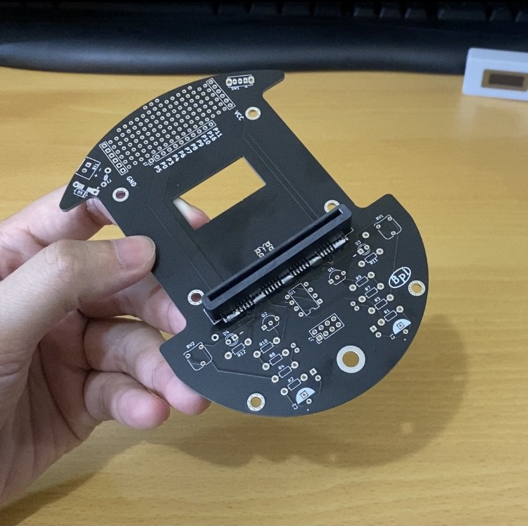
The first thing I recommend doing is to solder on the edge connector, this is one of the big components of the pack, and there wouldn't be enough space to fix or adjust if there are other components in the way.
![]()
(Photo of installed edge connector)
Resistors are known for their current-limiting capabilities. There are a few types of resistors used on the Triode Car, namely the fixed resistor, potentiometer, and photoresistor.
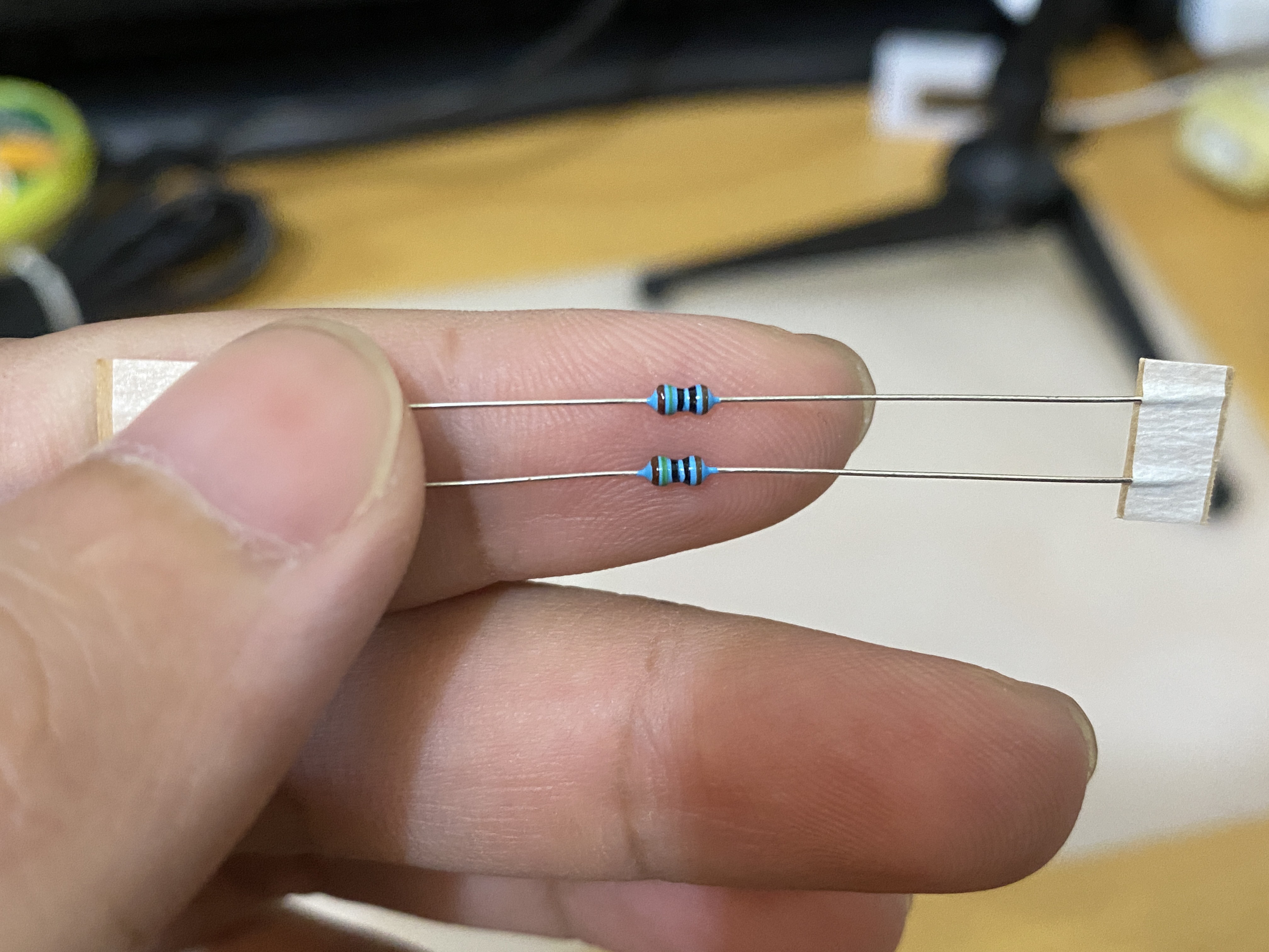
Fixed resistors are the most common component on any electrical circuit. Due to the electrical current limits that components can withstand are different, we usually see a ton of these on most circuit boards. The color bands indicate the resistance of the resistor. Generally, the most outward color band is the first band. With a quick google image search "5 band resistor color codes", we can now identify the resistor values. The first 3 bands indicate the base value, and the fourth band is the multiplier.
(Photo of a fixed resistor)
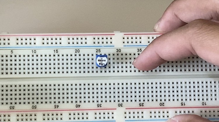
The potentiometer is a type of variable resistor, its value of electrical resistance can be adjusted to perform different behaviors. For example, some fans use potentiometers to control fan speed. Lamps oftentimes use potentiometers to adjust brightness. Every car assembled won't be exactly the same, it often requires a bit of tuning. The potentiometer will help us adjust the precision of the line tracking feature.
![]()
(Photo of the potentiometer)
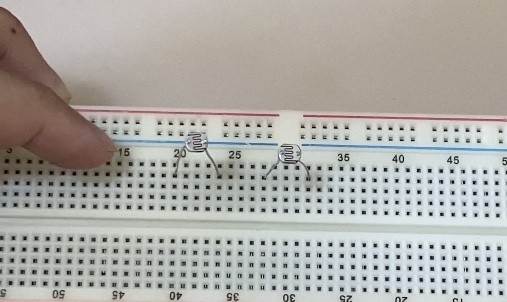
The photoresistor is also a type of variable resistor. However, the electrical resistance is determined by the brightness of the environment. The brighter it is, the lower the resistance. Conversely, the dimmer the environment, the higher the resistance. These will be the main sensors that we will be using to enable the line tracking capabilities of the Triode Car.
![]()
(Photo of the photoresistor)
After installing these parts onto the board, we have completed the hardest part of the assembly. I've recorded the entire process on YouTube. Next update we will be wrapping this up by installing the remaining components and get it ready for testing. Stay tuned for more!
 Joey Shyu
