As mentioned in an earlier log, the gimbals use Hall Effect sensors. Below shows the magnet with the sensor PCB removed.
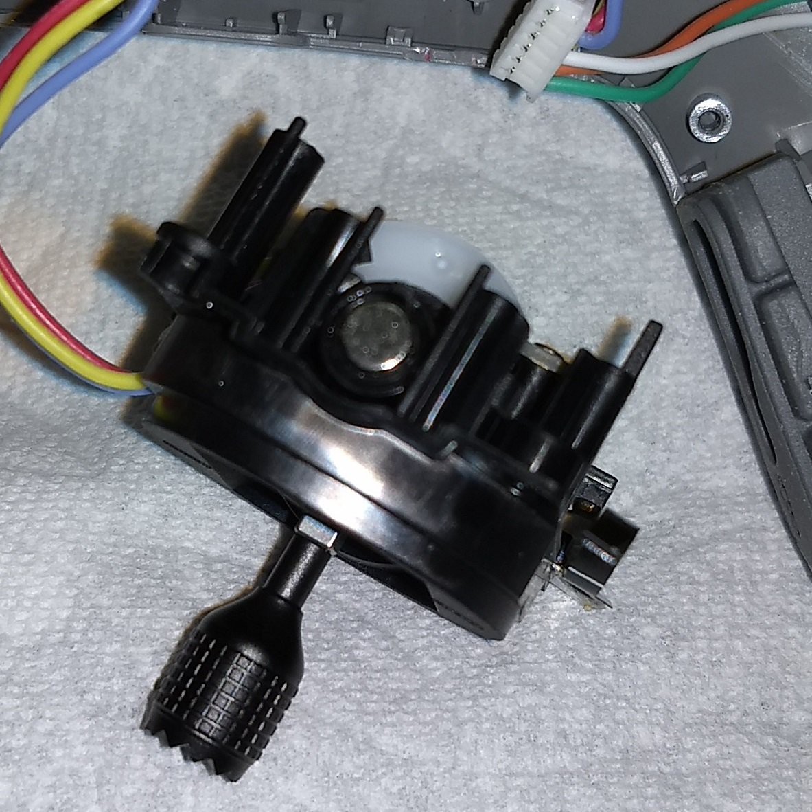
The gimbal in the photo below has one sensor PCB in place and the other sensor PCB removed.
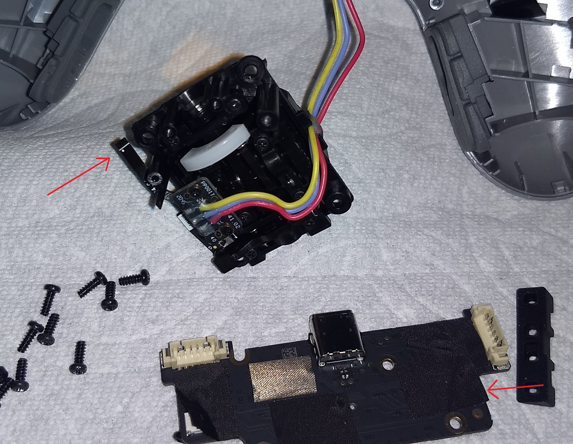
The small button is on a flat flex cable. The cable connects to the USB board. The above photo has arrows pointing to the two connectors which are normally mated when assembled.
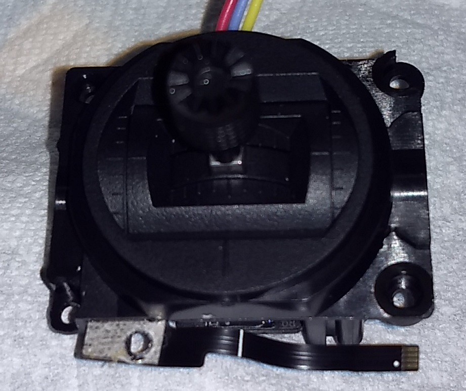
Below is the left gimbal with the flax flex cable show at the bottom of the photo. The small switch is not in view in this photo.
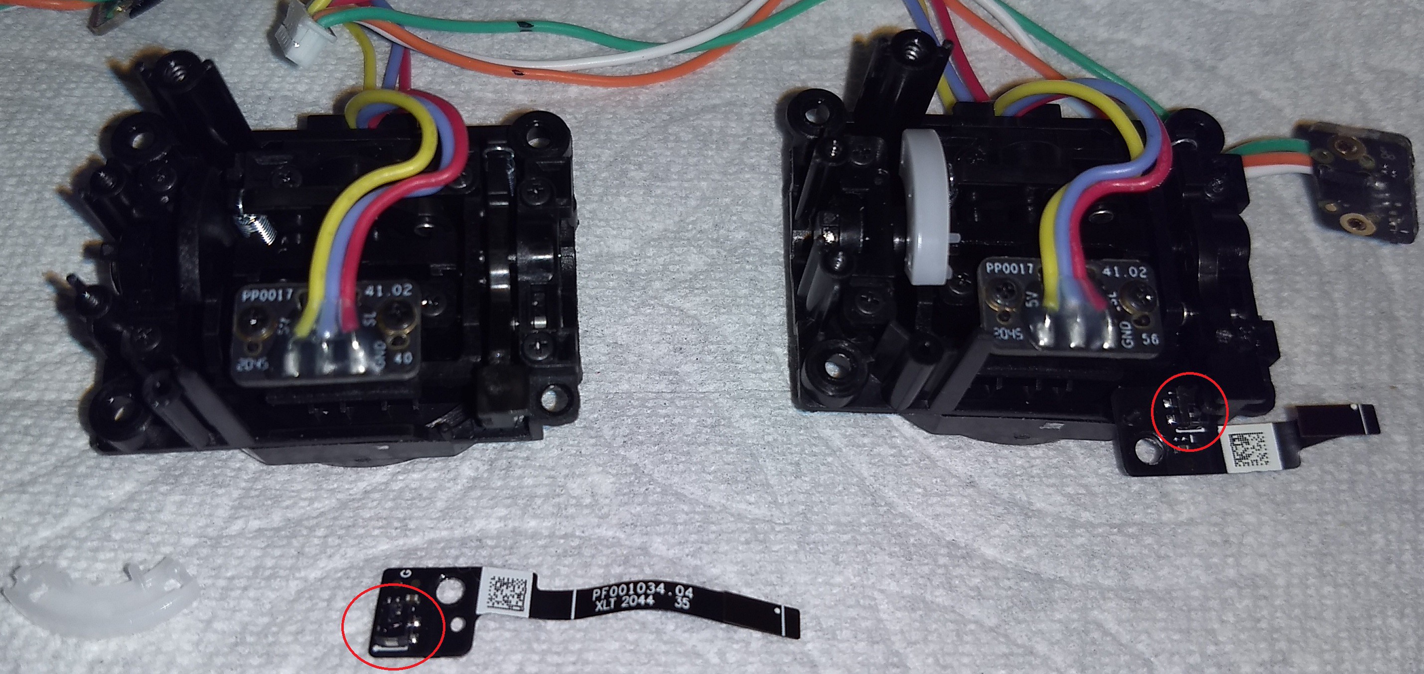
The small button and white plastic friction liner have been removed from the left joystick in the photo below. The two small buttons are circled.
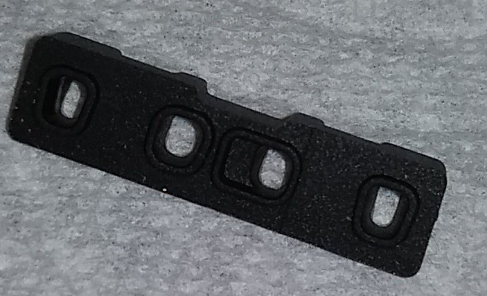
Below is a rubber light shroud to isolate the LED on the PDB with the USB connection.
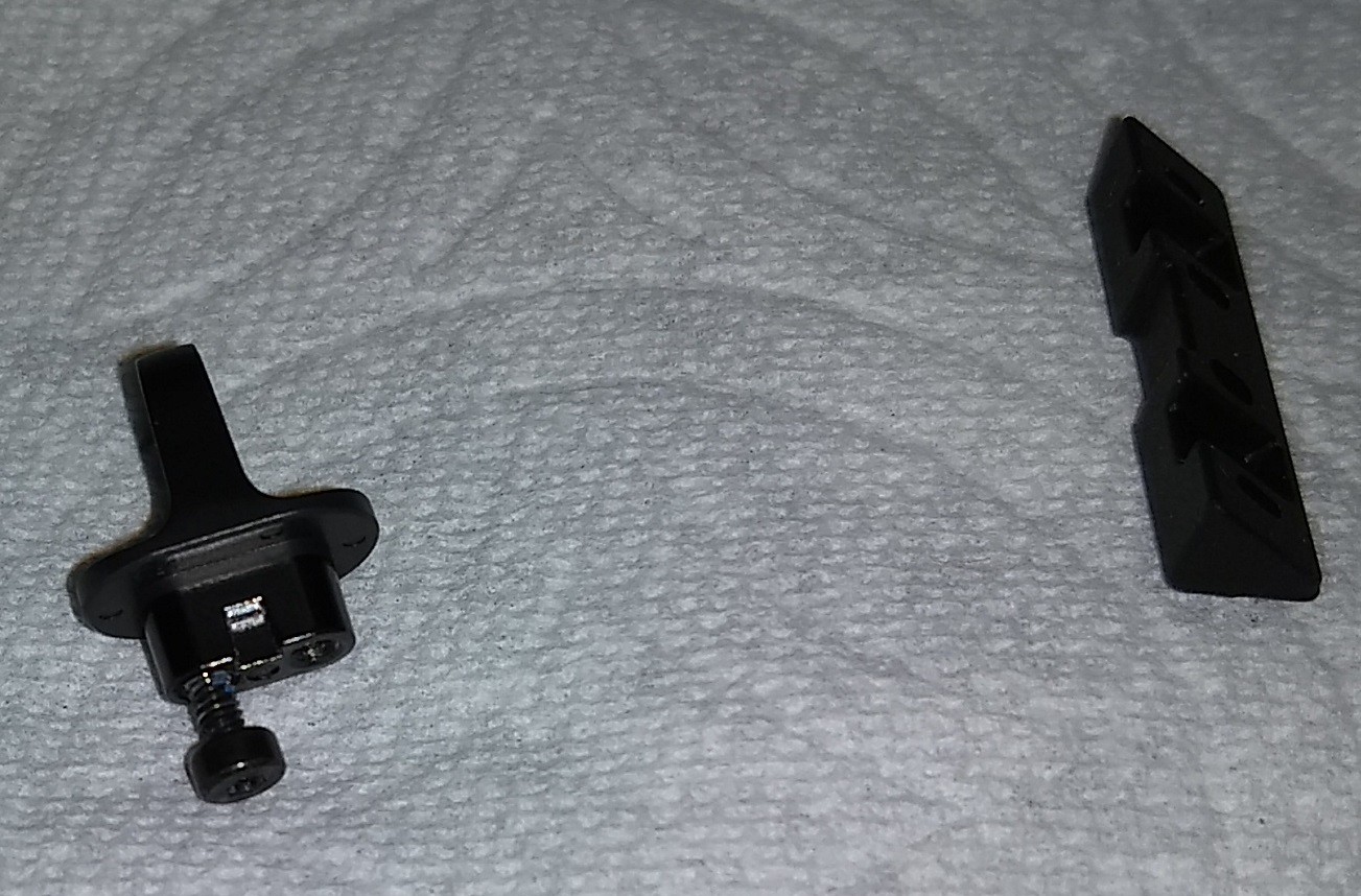
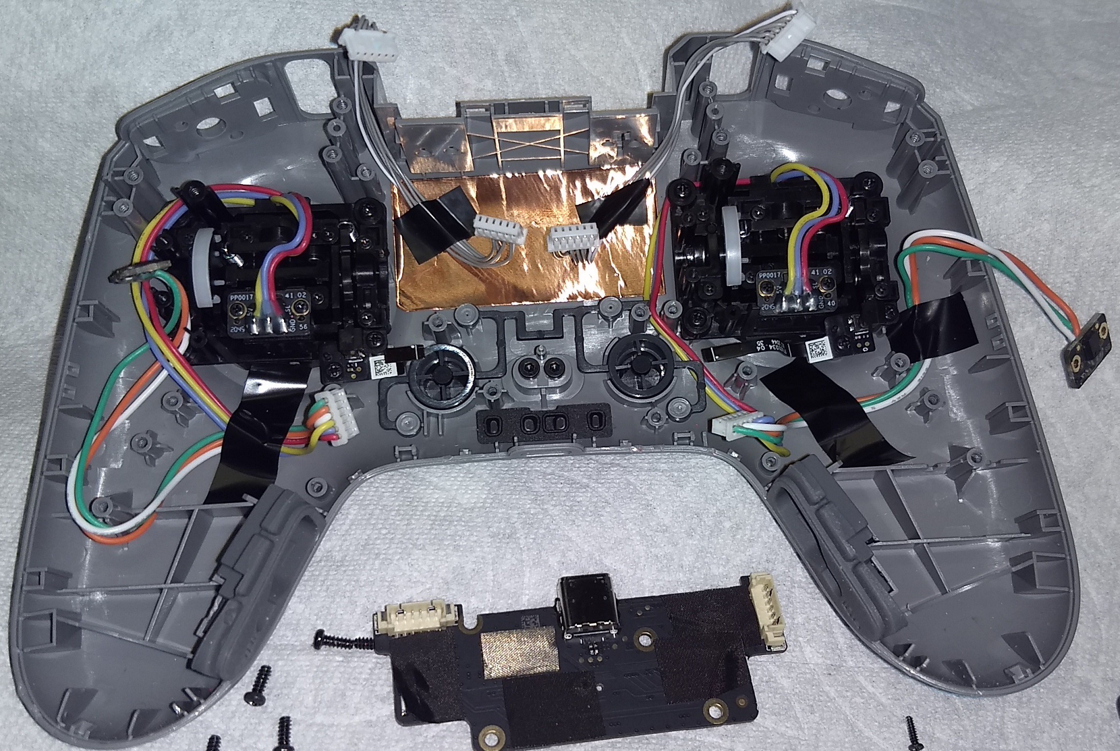
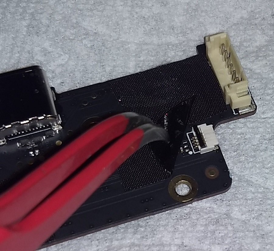
Above shows the USB PCB rotated 180 degrees. The charge state LEDs and two buttons are on the other side of the PCB. This PCB has connector to accept the flat flex cables with the small switches.
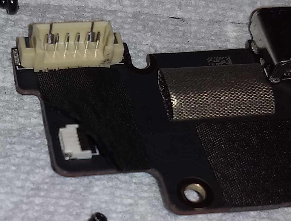
To be continued.
 Duane Degn
Discussions
Become a Hackaday.io Member
Create an account to leave a comment. Already have an account? Log In.
Do you think it feasible to transplant the board from this controller into the original DJI FPV remote (the black one) and hook up to the bigger gimbals?
Are you sure? yes | no
do you have any thoughts about hacking the hall gimbal sensor by replacing it with arduino and DAC ? (better ask some advices before blowing up my controller =p)
Are you sure? yes | no
I'd suggest measuring the gimbal voltage before substituting with a DAC. I don't know if the gimbals use 5V or 3.3V.
I haven't tried the DAC trick myself yet but I plan to try this in the near future.
Are you sure? yes | no