-
1STM32 Blue Pill preparation
For Arduino Nano, this step is not required.
Prepare the STM32 Blue Pill board using instruction from this link: https://www.electronicshub.org/how-to-upload-stm32f103c8t6-usb-bootloader/
-
2Upload DC servo controller software into STM32 Blue Pill or Arduino Nano
Download the DC servo controller software from: https://github.com/patlhy/PID-DC-Motor-Servo-Controller/tree/master/ArduinoTB6612PIDController
For Arduino Nano, edit the config.h file so that "#define NANO" instead of "#define STM32" is in the file before uploading.
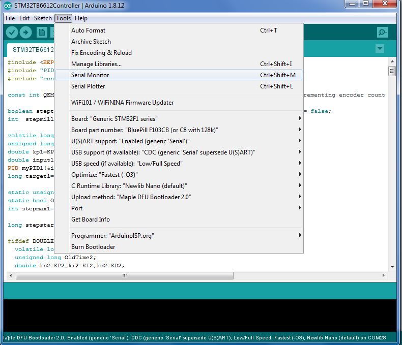
For STM32 Blue Pill, set "#define STM32" in the config file and upload with the following settings:
![]()
-
3Hardware Connection
For Arduino Nano, connect the board to TB6612FNG driver board as per the wiring diagram below.
NanoTB6612 connection diagram.pdf
Connect STM32 blue pill board to TB6612FNG driver board as per the wiring diagram below.
STM32TB6612 connection diagram.pdf
Please note that if you use the USB port to power the STM32 blue pill board, do not connect the 5V power to STM32 board. Connecting both at the same time may cause damage to the board as STM32 blue pill does not have a protection diode between the 5V pin and the USB 5V pin.
-
4Download and run PID tuning software
Download the PID Motor Controller Tuner software from: https://github.com/patlhy/PID-DC-Motor-Servo-Controller/tree/master/PyPIDServoMotorTuner
This Python software can only run if you have Python 2.7 installed in your system. In most Linux system, it is pre-installed by default. However, in Windows you have to install WinPython and set the correct path to the Python interpreter.
This is the link for WinPython:
https://sourceforge.net/projects/winpython/files/WinPython_2.7/
Follow the instruction below if clicking on the PyPIDServoMotorTuner.py file does not start the Python interpreter:
https://github.com/winpython/winpython/wiki/Installation#Registration -
5PID Tuning
Start the PID Motor Controller Tuner (PyPIDServoMotorTuner.py) software and connect to the COM port of the Arduino Nano or STM32 board using the "Connect" button
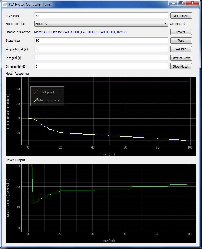
Change the PID values as below such that I and D term have zero values and start with a low PID values with P at a low value such as 0.2 to 0.5. After that, click on the "Test" button. If the Motor Response graph shows that the motor (yellow line) is moving away from the setpoint (red line) like the diagram below, this means the quadrature encoder is incorrect. Click on the "Invert" button to change the polarity of the encoders.
If the motor is turning continuously, try clicking on the "Stop Motor" button to stop it. In some situation, "Stop Motor" button may not work. The only option is to switch off power to the Motor.
![]()
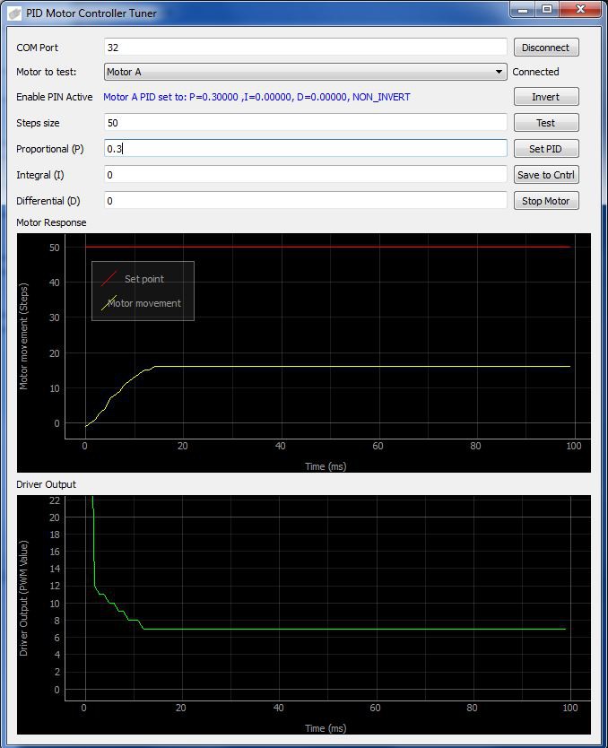
The diagram below shows the encoder connected in the correct polarity. The Motor Response graph shows that the motor (yellow line) is moving toward the setpoint (red line).
![]()
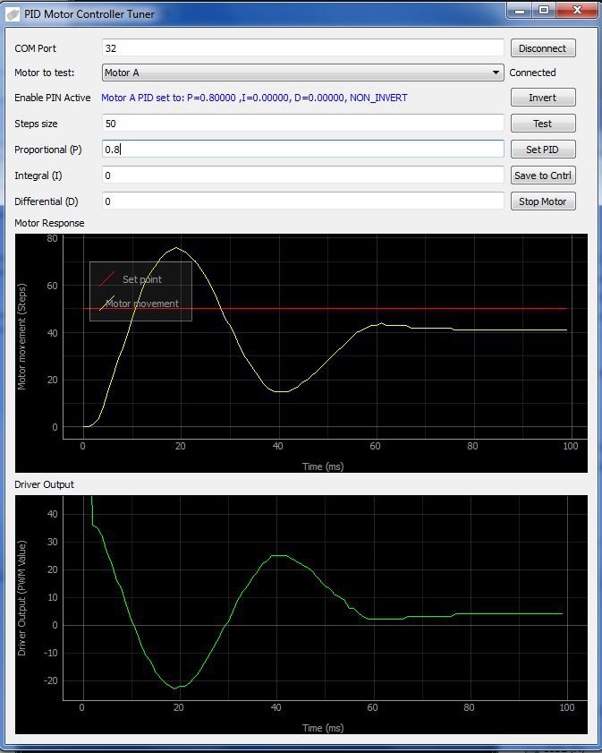
Increase the P value until the motor start to oscillate as below. After this, increase P value in smaller increment.
![]()
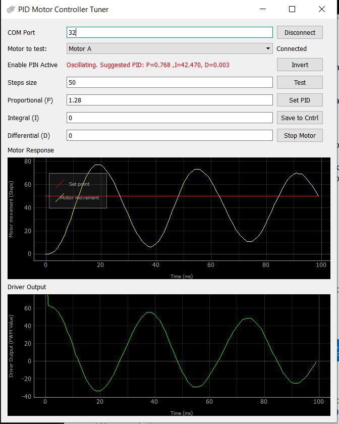
Increase P value further until the motor oscillate as below. The suggested PID values is calculated using Ziegler–Nichols method. This is explained in the Wiki link below:
https://en.wikipedia.org/wiki/PID_controller
![]()
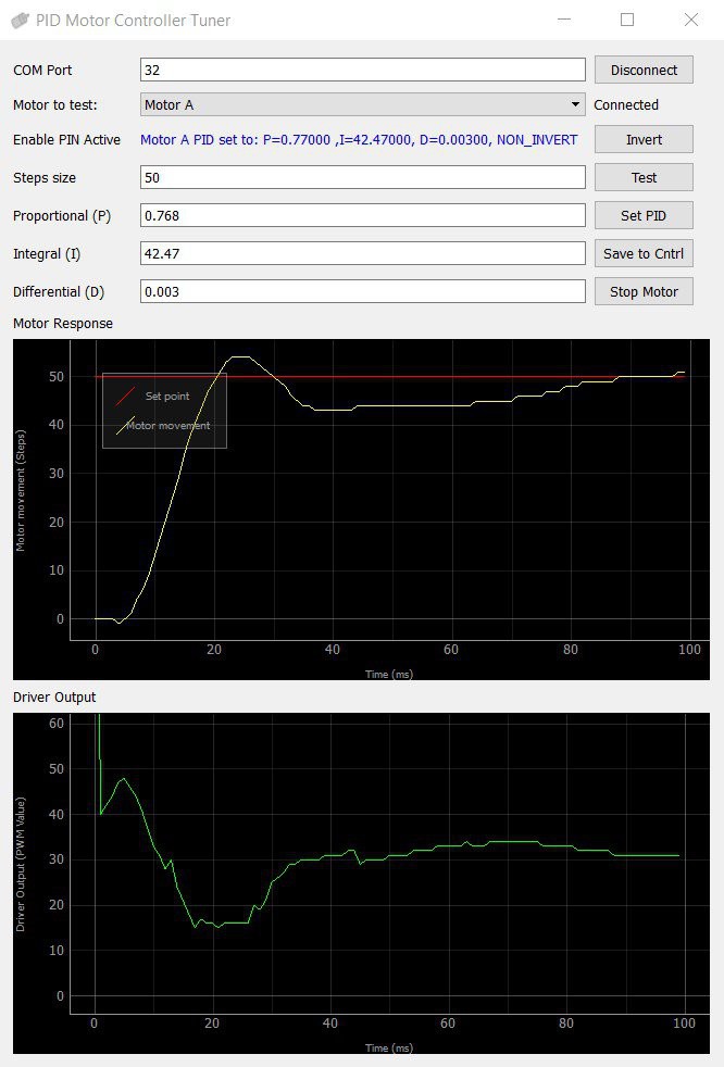
Key in the suggested PID values and click on the "Save to Cntrl" button. This will save the PID values into the EEPROM so that these PID values will be recalled when the controller is rebooted.
These values will give a response with an overshoot like the screenshot below.
![]()
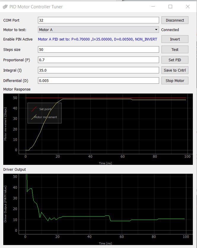
The overshoot can be reduced by increasing P or D or reducing I parameters. The response below shows a response with less overshoot after adjusting the PID parameters.
![]()
Stepper to DC Motor Conversion
Control DC Motor position from driver sockets meant for A4988 or DRV8825 stepper driver
Discussions
Become a Hackaday.io Member
Create an account to leave a comment. Already have an account? Log In.