 Deepak Khatri
-
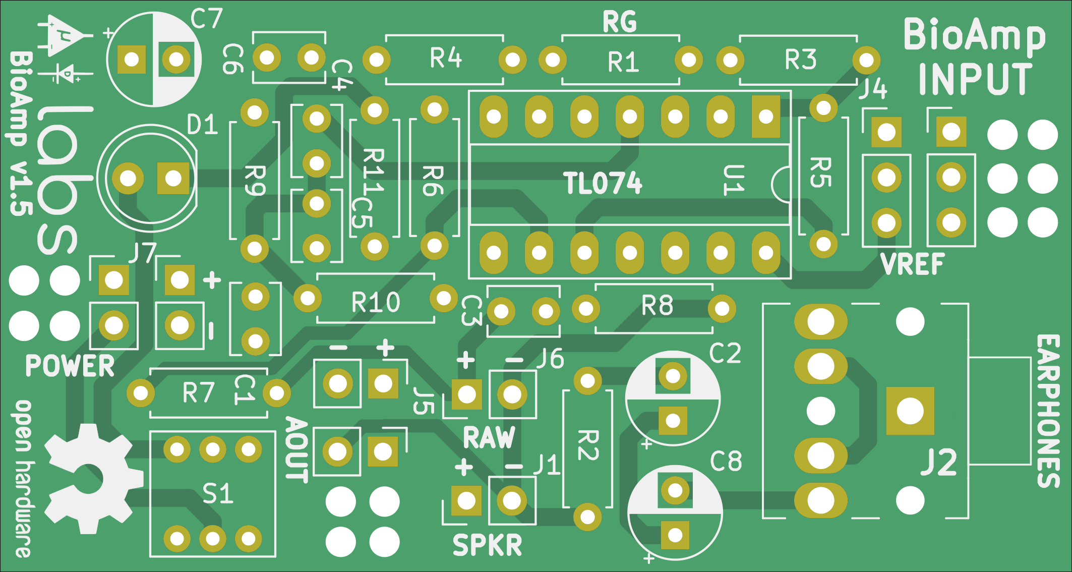
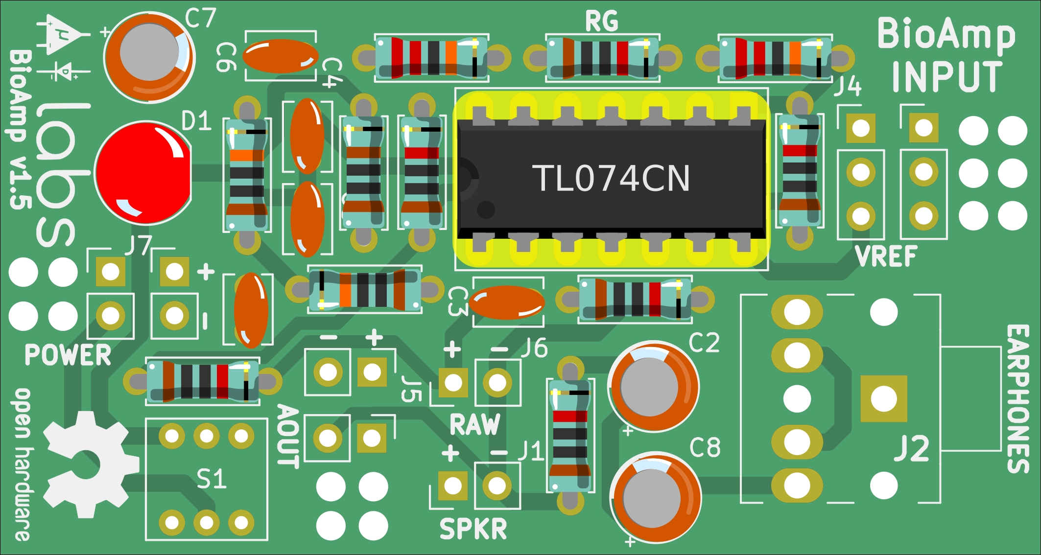
1Blank PCB
Order the BioAmp v1.5 Kit from Tindie and you'll receive a PCB just like shown below.
![]()
This PCB is the starting point of our build, solder components as per the instructions below to get your own BioAmp v1.5 ready to record BioPotential signals. Keep this interactive BOM link handy to help you with the build process.
-
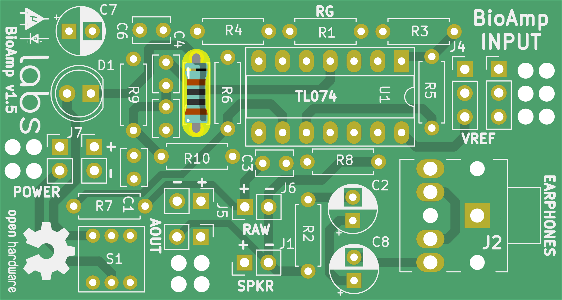
2Resistor 1k
We will start with all the resistors first, for this step you solder a 1k resistor at R11 as shown in the interactive BOM. The image below shows the exact placement.
![]()
-
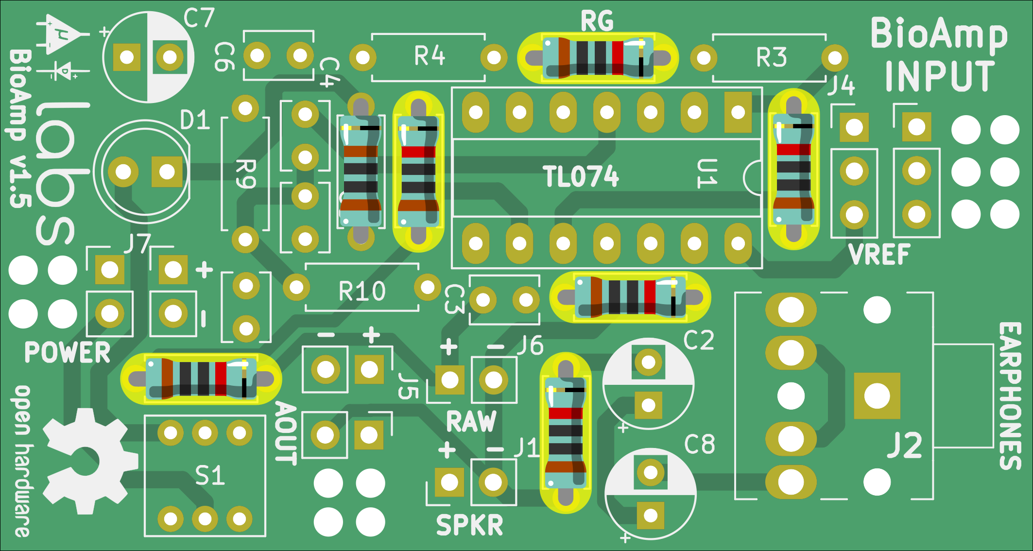
3Resistor 10k
Solder 6 x 10k resistors at R1, R2, R5, R6, R7, and R8.
![]()
-
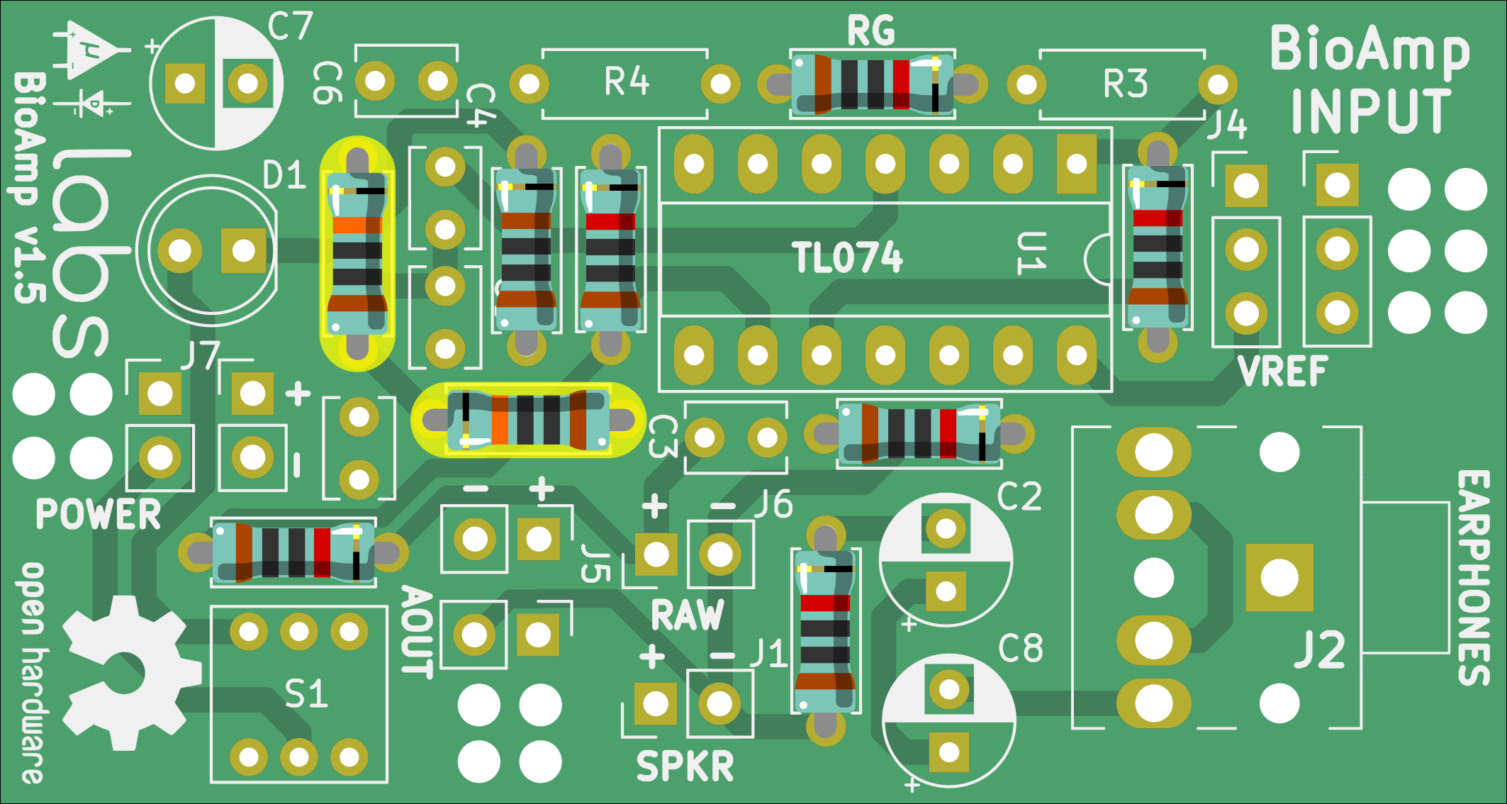
4Resistor 100k
Solder 2 x 100k resistors at R9 and R10.
![]()
-
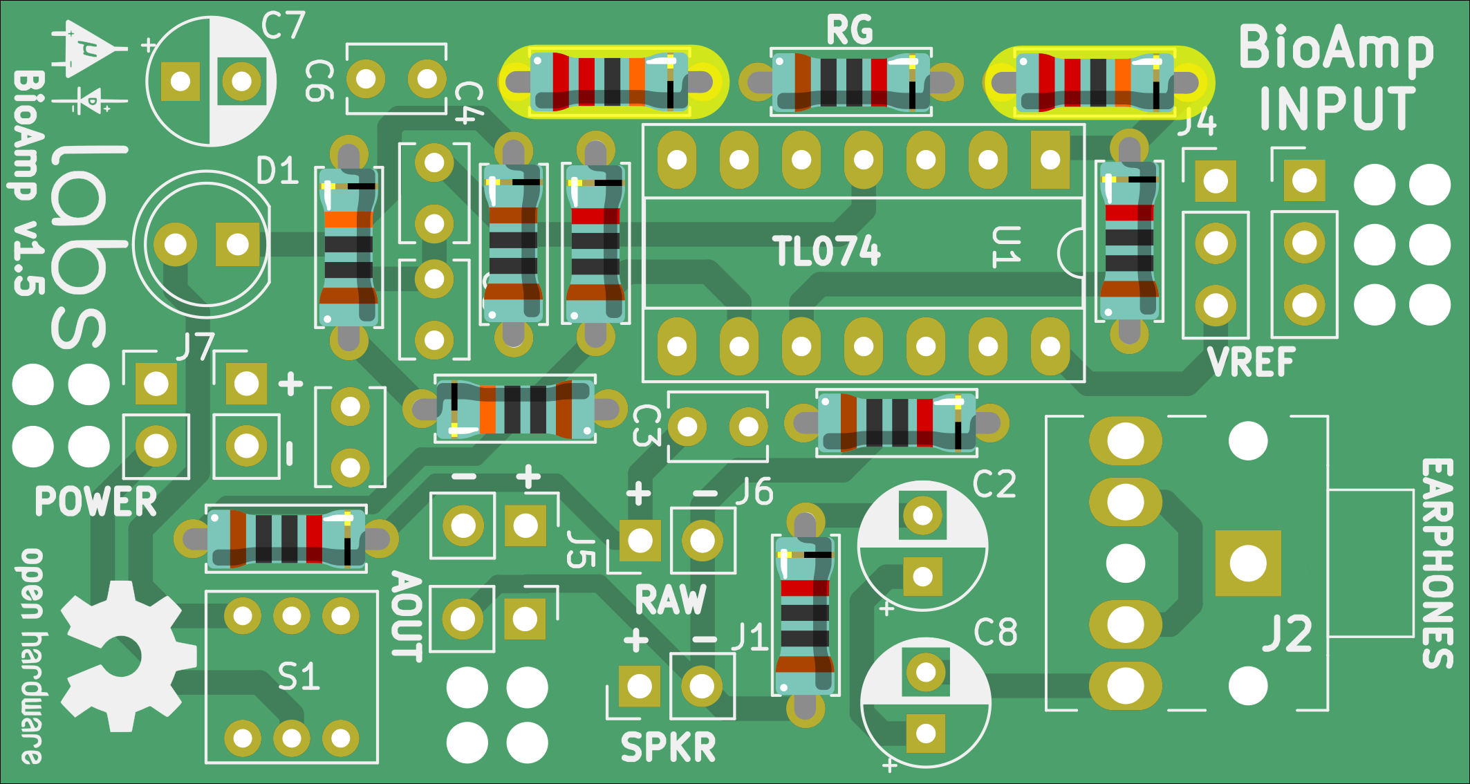
5Resistor 220k
Solder 2 x 220k resistor at R3 and R4.
![]()
-
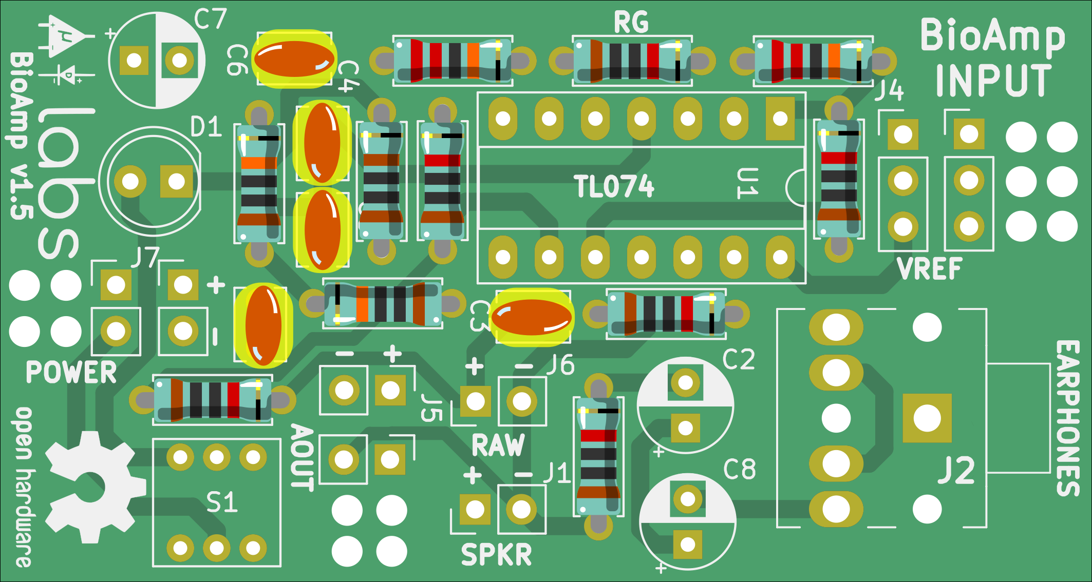
6Capacitor 100nF
Solder 100nF disc capacitors at C1, C3, C4, C5, and C6.
![]()
-
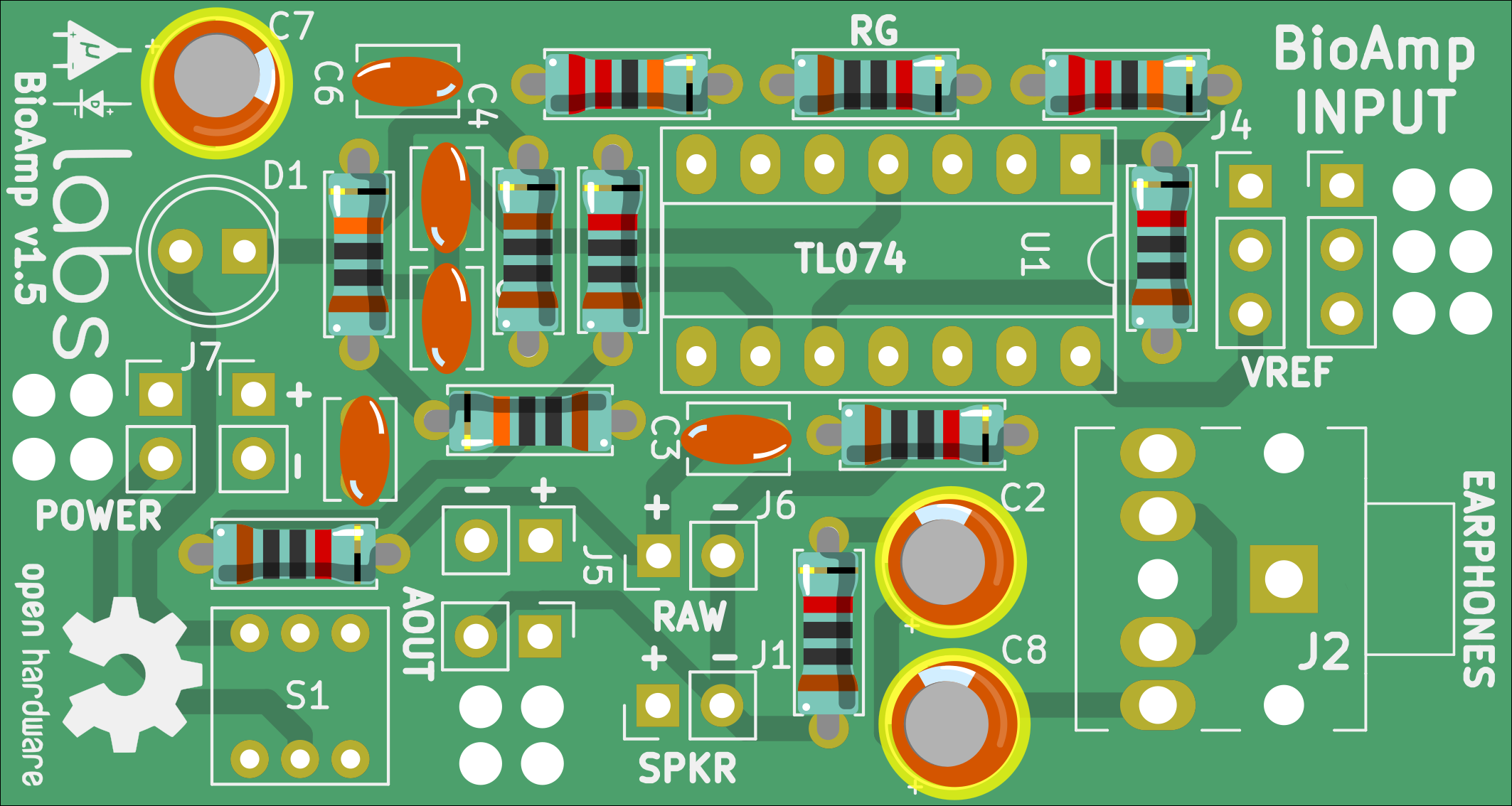
7Capacitor 47uF
Solder 47uF capacitor at C2, C7, and C8.
![]()
-
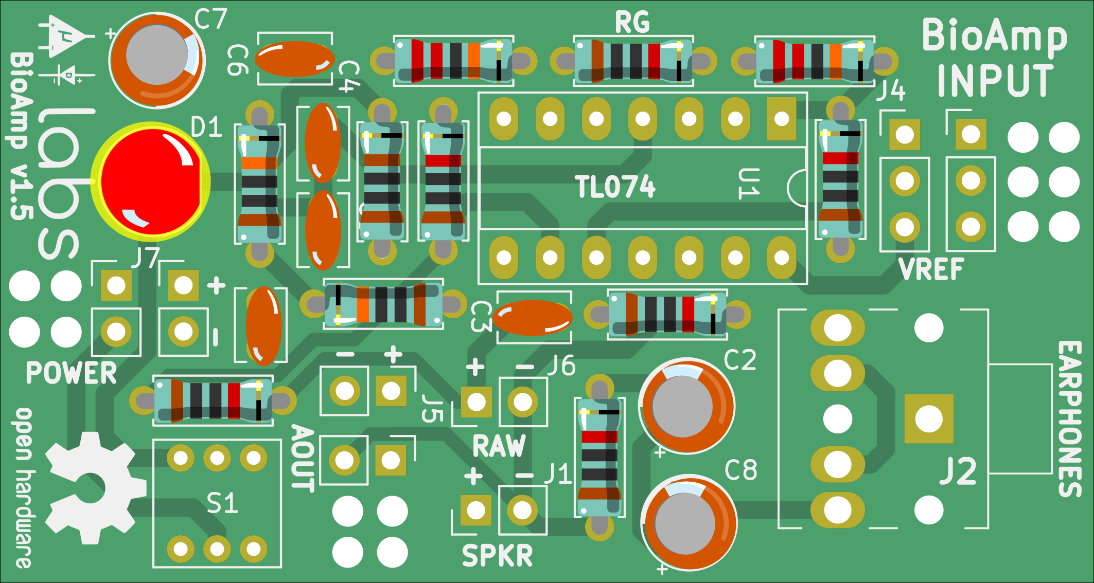
8LED
Solder LED at D1.
![]()
-
9IC socket
Solder IC socket at U1.
![]()
-
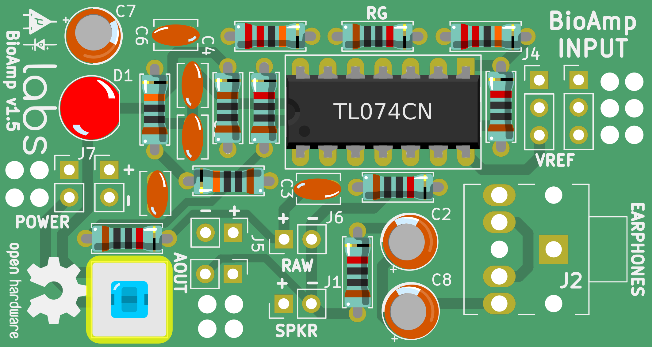
10DPDT Switch
Solder DPDT switch at S1.
![]()
Discussions
Become a Hackaday.io Member
Create an account to leave a comment. Already have an account? Log In.