 Dominik Meffert
New Layout
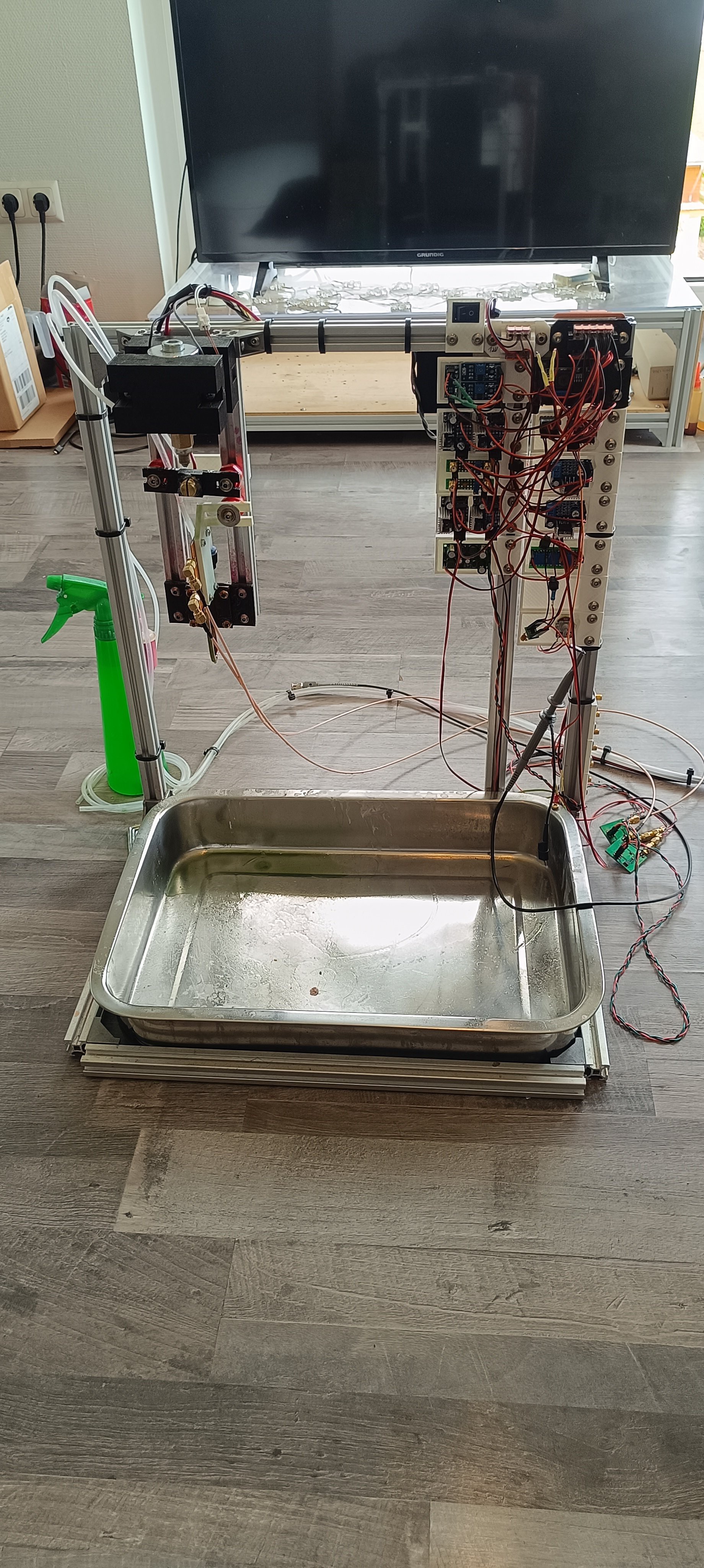
Over the last few days, I completely disassembled and reassembled the printer to tidy up the wiring, plumbing, and component arrangement to use previously unused space. To reduce the overall footprint of the machine, I changed the layout from a horizontal to a vertical design, placed the tank and bottles in front of the machine, and also removed all parts from the backside of the grid.
With the new layout, the machine now has a similar width and depth as the typical 3D printer - it's just a little taller.
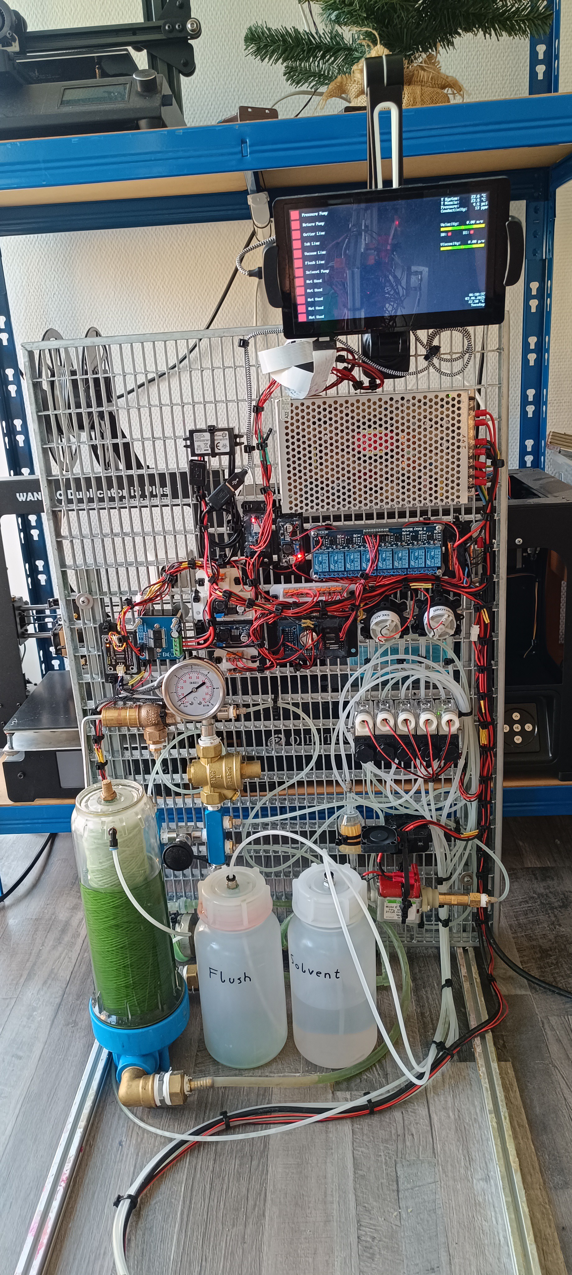
All of the components are now mounted on the front of the grid, and with that, also all of the weight, so that the machine only needs support feet at the front side since it wouldn't tip towards the backside.
This way, it's now possible to place the machine pretty close to a wall to reduce the space it takes in the room.

Components
With no longer any components hidden at the backside, it's now possible to see all used components at once, which I hope will make understanding the function of the machine easier.
Here is a small list of the machine's components, starting from the bottom of the machine:
Flush bottle, solvent bottle, ink tank with vent and return line inlet at the top and in and outlet at the bottom of it, silicone tube with check valves, damper, pressure pump with fan, gutter filter, fluid distribution assembly made of low-pressure side with inlet from relief valve, TDS sensor, temperature sensor and outlet/inlet for draining, maintenance valve, and high-pressure side with inlet from pressure regulator, pressure sensor, connection to damper and connection to ink valve.
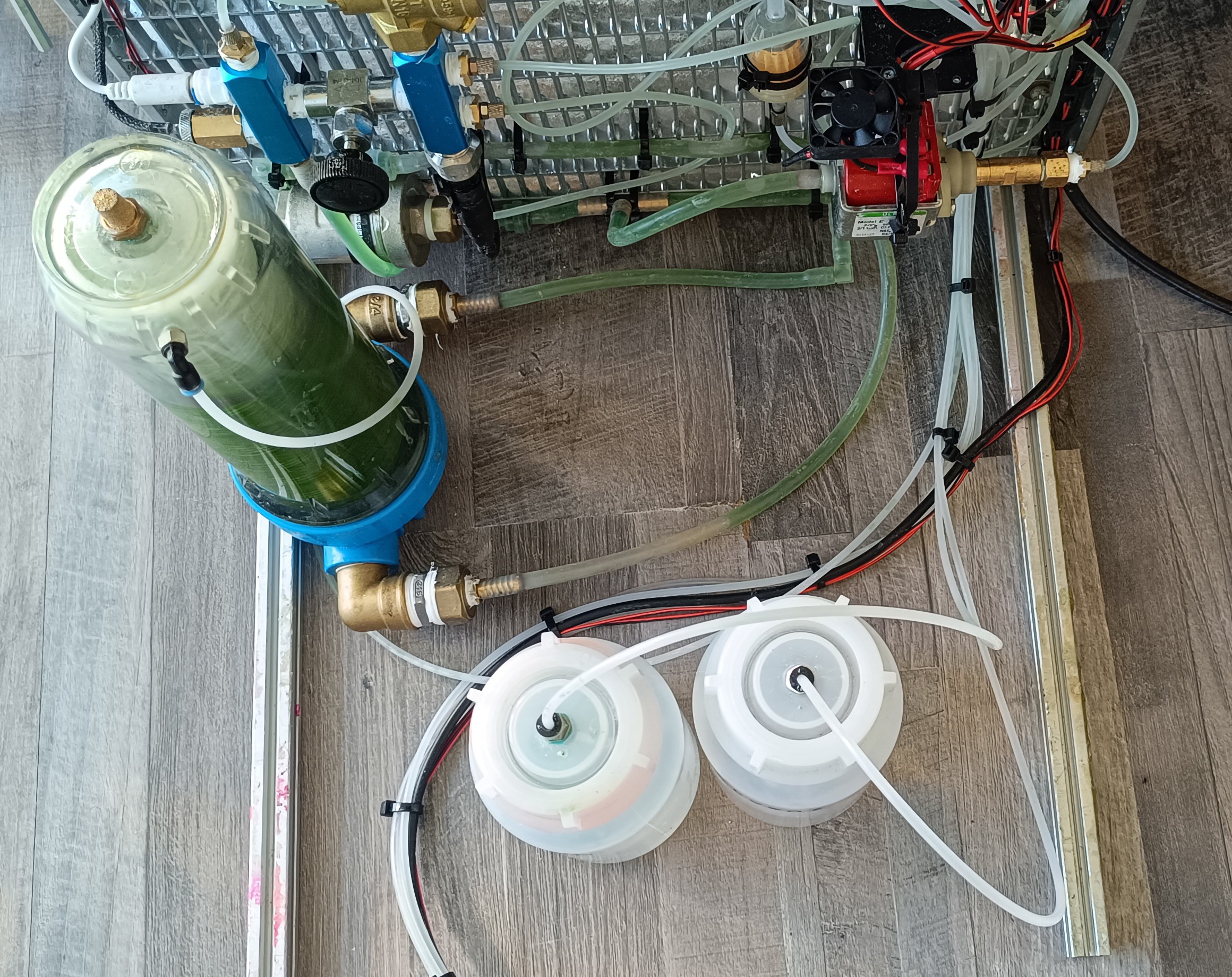
Starting on the left of the picture:
Relief valve, pump pressure gauge, and pressure regulator. Valve assembly on the right with the solvent pump and return pump above it.
Valves from left to right are the ink valve, vacuum valve, gutter valve, flush valve, and tank valve.
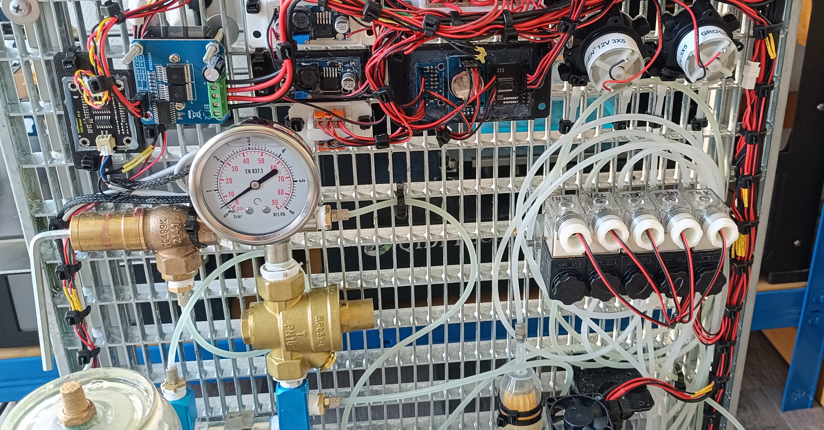
Almost all of the electronics are located in the middle of the grid to keep it organized. The only exemptions are the lines leading to the sensors, pumps, valves, and printhead.
Starting on the left of the picture:
TDS sensor amplifier, BTS7960 for pressure pump, LM2596 for solvent pump, LM2596 for return pump, WAGO distribution for I2C, WAGO distribution for 24V, USB power supply for LCD, AMS1117 3.3V for 3.3V to 5V level shifter, LM2596 for 5V logic, WAGO distribution for 5V, ADS1115 for the sensors, DS3231 for time and date, MCP23017 for digital IO, 8ch relay module for switching the valves, WAGO distribution for 24V and GND of the valves, main power supply 24V 10A.
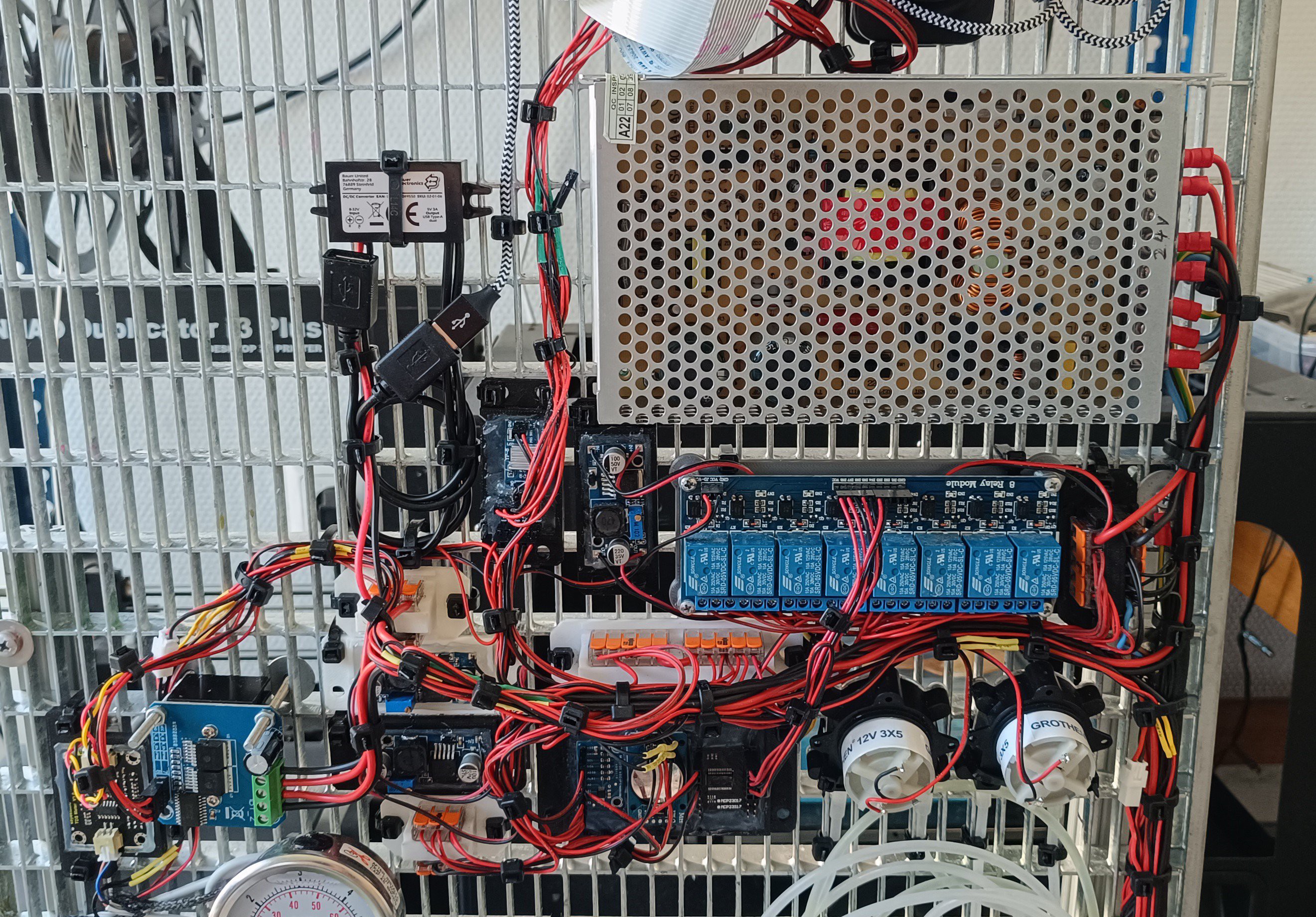
I think this is the first time I listed all of the electronics used for fluid management together since they were spaced all over the machine before.
At some point in the future, the printhead driver electronics and high-voltage power supplies will also be added to the machine.
I'm currently working on these but it will still take more time to get them ready. TOF is working; Phasing will be next.
The LCD is now mounted on a tablet holder at the top of the frame.
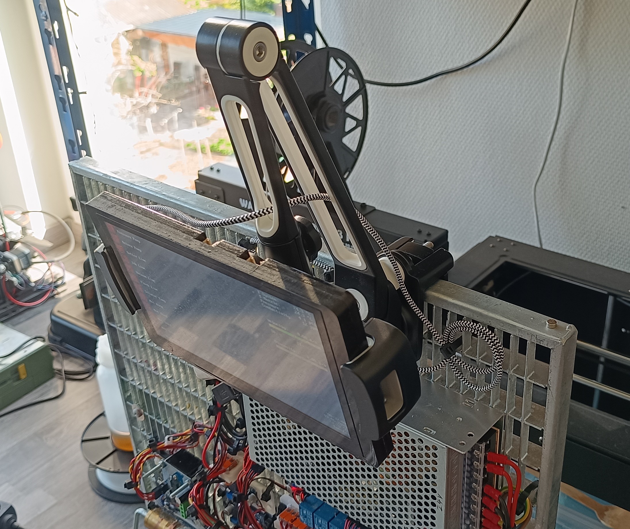
I think with the new layout the CIJ printer prototype now looks a bit less experimental than before. My plan for the future is to place the machine on the floor next to a plotter or other machine on which the CIJ printhead can be mounted for applying ethanol-based ink, varnish, or glue to a surface.

With that, optimization of the fluid management part is done for now and I will continue working on the printhead driver electronics, so that I can hopefully soon get the phasing to work.
Discussions
Become a Hackaday.io Member
Create an account to leave a comment. Already have an account? Log In.