Josh Cole
-
Gravity
06/06/2021 at 20:34 • 0 commentsThe moment I've been waiting for has finally arrived. Testing the algorithm!
So it turns out, the code I wrote originally is more or less workable. With a few simple tweaks, I am able to get everything working. With the following exceptions:
- The battery cannot be mounted in the top rack
- If bbot over-corrects at any point, it's all over. It may take 1 second, it may take 4 seconds, but the oscillation will ultimately be its downfall
- Torque is tricky
Some Challenges
The very first problem I ran into was that I couldn't juice enough torque from my motors. It would either be too slow, or too weak. So I swapped out the 12v steppers with 3v steppers (which have a higher amperage rating), and then proceeded to experiment with over-clocking the voltage in order to increase the torque.
I'm using L293D H-Bridge drivers which, as it turns out, are ancient relics of a less civilized age. They have serious voltage drop, which I think explains why I'm getting such awful torque.
Many voltages later, I still can't get it to overcome gravity. It's so close, but the angle-of-attack at which critical-failure happens is just too dang low. As a reality check, I removed the battery pack from inside bbot, effectively reducing the overall weight significantly. Lo and behold - it actually works (mostly)!
I'm planning to redesign the robot such that the battery pack is housed at the lower level. This might work. Idk. My other idea is to add yet another battery to increase torque. But I need to be careful, as I'm nearing the amperage limit.
The Accelerometer
By the way, I forgot to mention that I cast the HMC5883L asunder. It's truly not great for my application. The sheer sensitivity to magnetic fields, the inconsistent readings, the fact it never really quite worked... *sigh*
I've invested (a whole 3$) into an ADXL335 triple-axis accelerometer. This thing is badass. No calibration required and no sensitivity to magnetic fields = pure happiness. It just worked right out of the box.
So all that calibration work I focused on earlier was for naught. But that's okay - it was actually a lot of fun to explore the limitations of the HMC5883L. Knowledge is power! And I learned that particular unit wasn't for me.
-
Circuit Board v4
06/03/2021 at 06:42 • 0 commentsAfter what feels like a lifetime, I've finally received the fourth revision of my circuit board!!! Woohoo! The fab that I've been using is called JLCPCB and they are fantastic. Really cheap and super fast delivery.
Why am I on rev 4, you may ask? Well... some mistakes of the past include:
- Bore sizes for custom footprints are too small
- Arduino chip facing inwards, so you can't access the USB port
- Rogue 12v wire connected to 5v input on the L293D
- Distinct lack of noise filtering capacitors.
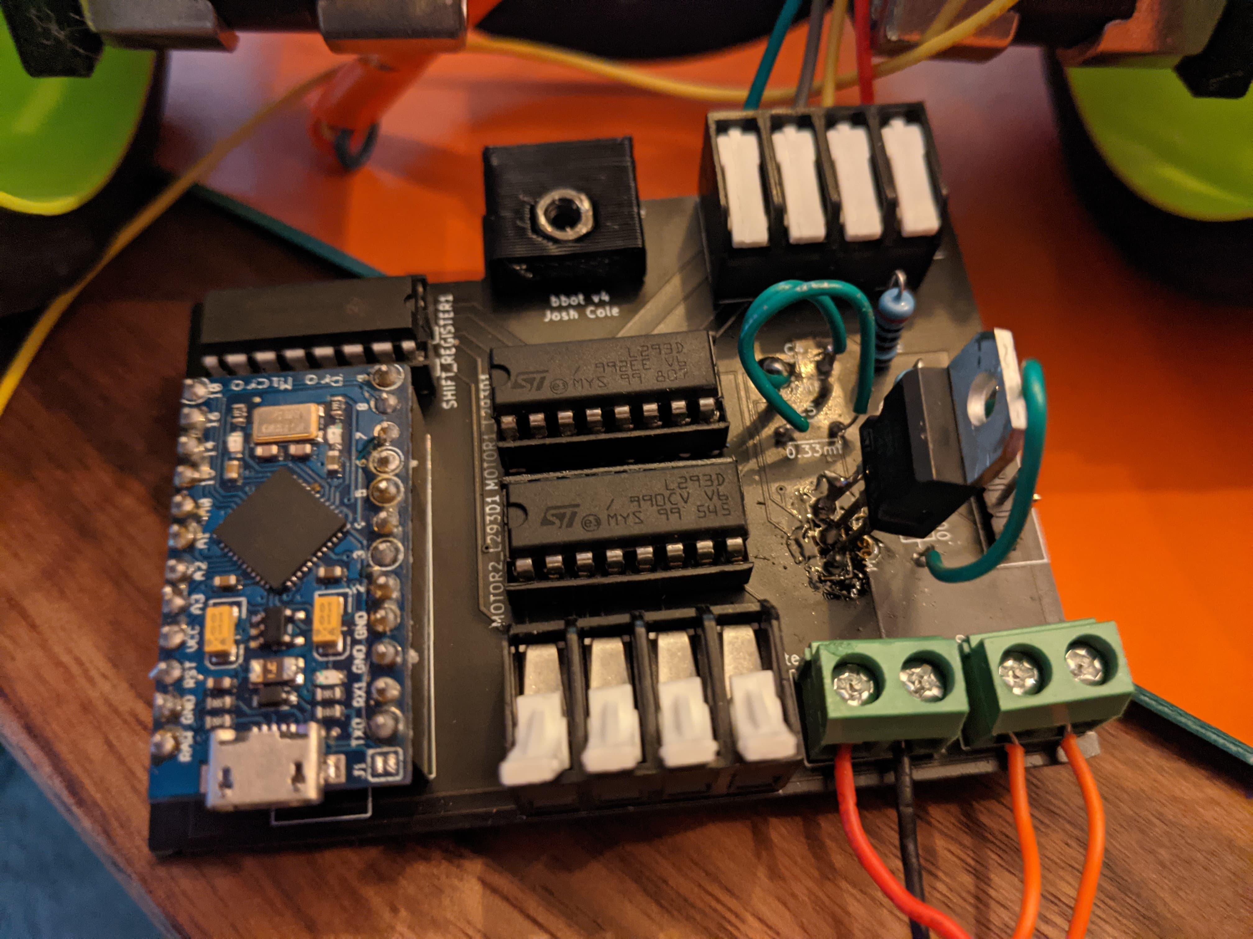
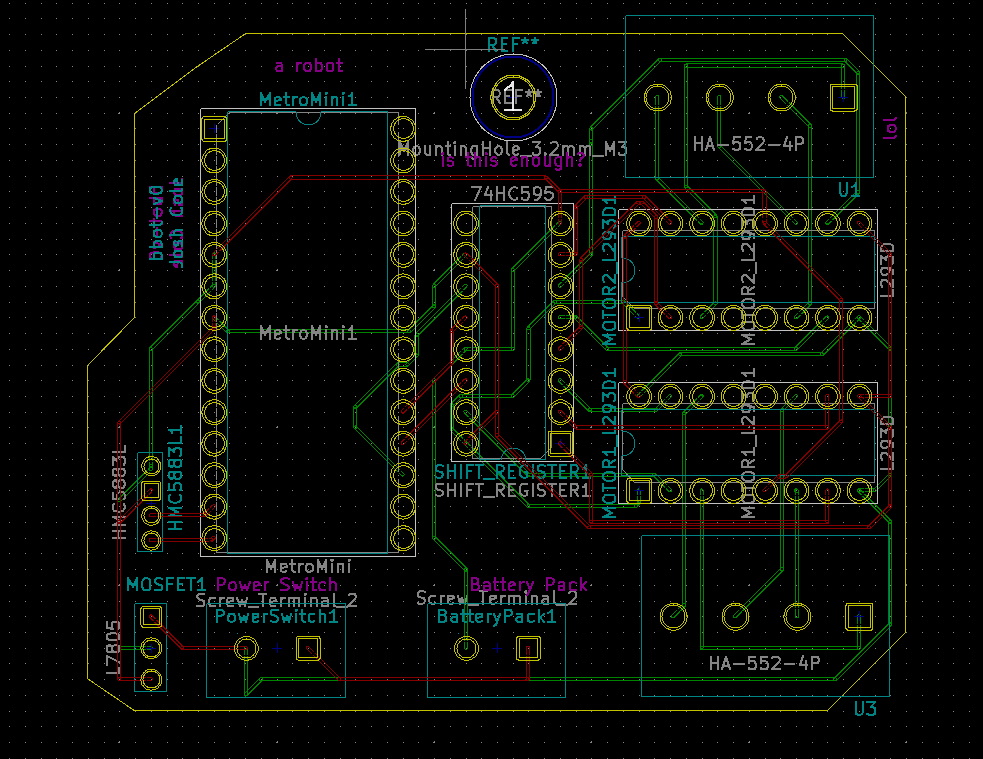
After fixing all those issues, we are left with the glorious piece of engineering you see below. If you look closely, you may notice a number of hacks. That's because, as it turns out, 4th time is NOT the charm. The main mistake I made this time...
- Capacitors are not supposed to be wired like a switch... How did that even happen!?
That being said, I didn't really need those capacitors anyway. So I just added jumpers which are able to complete the circuit. I'm going to be putting this all together and then we'll see what happens!

-
Data Logging to Calibrate HMC5883L
04/25/2021 at 18:43 • 0 commentsI have entered this project into the data logging contest because of the work I did to analyze and calibrate the HCM5883L magnetometer. It wasn't the whole point of my project, but I think it's a fun look at how visualizations can help understand what's happening.
The ultimate goal of my project is to create a two-wheeled robot which is capable of defeating gravity in a real-time battle against the forces of nature. One of the first major decisions to make: which accelerometer do I use? Having a few HMC5883L sensors lying around, I decided to create a small circuit to collect telemetry and see whether it would be a good candidate for my robot.
RUBBISH
As a sanity check, I wrote a small program to collect the raw sensor readings and then looked at the numbers as I rotated the device about all of its axis. Much to my surprise, the values were all over the place. Rotating along two axis (what I imagined were X and Y) caused all three numbers to change. That's not a good sign, but looking at raw numbers can be a hard thing for humans to make sense of. It's time to open a Jupyter Notebook and plot the data.
IDENTIFYING WHICH AXIS REPRESENT DIRECTIONAL HEADING
The first actual experiment began by mounting my sensor to a large base and then spinning that base like a turn-table. The idea is that if I can isolate the X/Y coordinates and produce a heading, the remaining plane will indicate rotation. With this information, I can apply virtual offsets to the readings to "normalize" the plane.
Collecting this data, I was able to plot it in matplotlib. I used a scatterplot to map two axis at a time. Presumably if I find the dimensions which represent "directional heading" that should appear as a perfect circle.
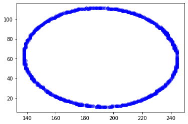
And in fact, I was able to find just that. Here are the visualizations:
X and Z axis are represented by this lovely oval. This would indicate that X and Z are representative of magnetic heading.
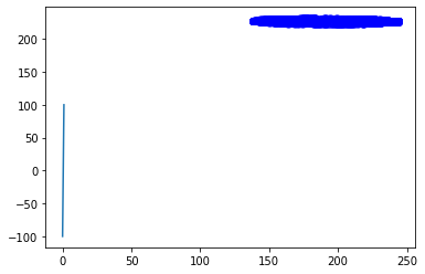
Y and Z are represented by these weird lines. I'm going to assume Y is rotation, and Z is one component of heading. So that means there's variance in the rotation based on which direction the sensor is facing. NOT GOOD!
And lastly, when plotting X and Y we can clearly see there is no correlation whatsoever.
So we now know that X and Z represent directional heading. As we can see by the second graph, the rotation seems to change based on which direction the sensor is facing. An easy win now is to calibrate the rotational axis so it remains flat no matter what the heading is.
CALIBRATING THE SENSOR
Here's some python I came up with to demonstrate how to normalize the rotation value. In pseudo-code, this function loops over each point in the dataset and computes the heading. It then stores a dictionary of values where the key is the heading and the value is the inverse of the actual sensor reading.
If you multiply that value, you will effectively zero out the reading.
def generate_calibration(cal_list_x, cal_list_y, cal_list_z):
    y_factor = {}
    y_factor_count = {}
    for idx in range(0, len(cal_list_y)):
        px = cal_list_x[idx]
        py = cal_list_y[idx]
        pz = cal_list_z[idx]
        h = round(heading(px,py,pz))

        if round(py) == 0:
            factor = 1.0
        else:
            factor = (1 / py)

        if h in y_factor:
            y_factor[h] += factor
            y_factor_count[h] += 1.0
        else:
            y_factor[h] = factor
            y_factor_count[h] = 1.0

    for k in y_factor.keys():
        y_factor[k] /= y_factor_count[k]

    return y_factor
To use the output of this function, you simply ask the robot "what direction am I facing" and then you will get a multiplier that you can apply to the current rotation reading. Any variance detected thereafter should be legitimate.
TESTING OUT THE CALIBRATION
To test out the calibration, it is imperative to isolate the variables as much as possible. I 3D printed a jig which has a 10-degree backwards tilt and then mounted my sensor to this jig. Given a known angle of rotation, it's much easier to collect meaningful data.
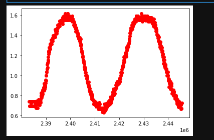
So now that my sensor is "calibrated" I went ahead and collected data at this 10 degree tilt. Then I rotated the sensor like a turn-table 360 degrees to the right. Then 360 degrees back to the left. Here is the visualization of the data I collected:
Looking at this chart, it's a little disheartening. The line should be flat if it were calibrated properly, however, the range of values is significantly better. So at least that's something.
INTUITION
I feel it in my soul that it should be possible to determine which orientation the sensor is tilted in (forward or backward) based on the heading we are facing and the sign of the component values. I just need to find the right correlative factors.
It's time to take a step back and plot some of the more nuanced datasets. For this next test, I apply the "turn-table" method while the sensor is rotated 10 degree forward. And then again, while the sensor is rotated 10 degrees backward.
Remember, Y is rotation and Z is a component of directional heading.
Given that, let's try another scatterplot chart. Since I suspect the sign of the components are relevant, I'm going to use atan2 to compute a sort of angle value. The input to atan2 is going to be Y and Z. This will be used to represent the X axis on the scatterplot. And the Y axis will be represented by how much rotation is being detected.
The atan2 function calculates one unique arc tangent value from two variables y and x, where the signs of both arguments are used to determine the quadrant of the result
If my theory is correct, the graph should be such that a line can be drawn through it which distinguishes the "tilted forward" from the "tilted backward".
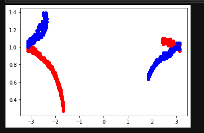
In this following chart, the red values represented "tilted backward" while the blue values represent tilted forward.
And holy smokes batman! That actually worked. If you draw a line down the center, you'll get a cleanish partition which divides the readings. Of course there is significant overlap here, but this is finally a positive sign that maybe - just maybe - I can salvage the readings from this sensor!
WE MUST GO DEEPER
Looking at the previous graph in more detail, a "line down the center" would still yield about 50% error rate. Haha. It's funny that I would be celebrating such an awful accuracy.
Holistically looking at the problem, I think it's safe to say the real root cause issue is that the sensors 0,0,0 plane (perfectly flat, not rotated, origin point) must be significantly tilted in a weird way. That means I need to apply some offsets to the X, Y, and Z values in order to "normalize" the plane so that my orientation is what it reads as the tabula rasa state.
Hypothesis: there exists a set of offsets that, when applied, would yield sensor readings that perfectly distinguish between the two datasets used earlier (tilted forward, tilted backward).
The only problem is, how can I find these offsets?
THE MONTE CARLO METHOD
The Monte Carlo Method is a strategy for attempting something randomly over and over until you reach a winning condition. As long as you can tell algorithmically whether a given solution is better or worse than another solution, the Monte Carlo method can be applied.
In this case, I wrote a tiny script which would randomize the sensor reading offsets. I applied this randomization tens of thousands of times until I found the best set of the batch. Given these offsets, the idea is that they will normalize the 0,0,0 plane and improve all other calibration efforts.
The results were fantastic! Like, I seriously can't believe this actually worked.
This chart was generated in the same way as before. X value is rotation, Y value is atan2(rotation, Z). If you were to write two if statements, you could near-perfectly extrapolate which reading was "tilted forward" vs "tilted backward". (which readings were RED or BLUE).
CONCLUSION
By logging telemetry, interpreting it with matplotlib, and applying some rusty trig - I was able to identify a set of multiplication values and offsets which yielded meaningful readings from the HMC5883L magnetometer. The sensor is incredibly sensitive to magnetic fields however, which may preclude me from using it in the final iteration of my project. But I have proven here that it works and learning to dive into the data has been a very rewarding experience.
I'm going to modify my circuit board to include a Sparkfun OpenLog so I can collect more telemetry. Surely that will help once I begin working on the stabilization algorithm.
-
Thoughts on Calibrating the Compass
04/10/2021 at 16:49 • 0 commentsI've been giving a lot of thought about how to calibrate the magnetic compass (HMC5883L). There are a few interesting qualities that I've discovered. First - the raw readings, even after self-test, are nonsensical. Technically I'm able to get linearly-scaled values. But they are in unexpected ranges. More importantly however, is that the motors themselves cause significant interference with the operational quality of the HMC5883L readings.
All that to say, I'm thinking of ways I can calibrate this thing. My current plan is very naiive, but I'm going to do some tests and see if it's feasible. At its most basic level, I'd like to discover an offset - and maybe a scale factor - in order to constrain the readings between 0 and 1. For this project, I really only care about the Z axis, as that will represent tilt. Although it would be nice to calibrate all axis so I have more opportunity for advanced functionality in the future.
Calibrating the baseline
So to calibrate, I'm thinking I'll mount the sensor roughly near its final resting place (so it can experience interference from the motors) and then I simply need to make sure bbot stays perfectly level, while I rotate the whole machine 360 degrees collecting data from the sensors all the while. Taking the maximum z value as an offset seems like a reasonable way to collect the baseline. Since it'll have been perfectly level, I know that any reading I get will just be potential noise.
Is that going to be enough? I'm not actually certain. My suspicion is that I'll find it works for some directions, and fails for others. If the values are non-linear, then my approach will need to become infinitely more interesting. I have thoughts on this, but I'll wait until I can prove whether or not they're relevent.
Calibrating the range
Once the baseline is collected, that means the sensor should read some static value when it's perfectly level. Next, I need to make sure that tilting the machine produces similarly consistent values based on the degree of rotation. Ultimately I intend to calculate how many steps per degree are required to actuate the motor in order to return to a level state. In this way I won't be over-correcting.
To calibrate the rotational range, I'm thinking I'll take bbot and rotate forward 90 degrees, then backwards 90 degrees. Repeat this a few times and collecting data all the while. Given these readings I can take the minimum and maximum and derive some kind of range which can then be used to constrain the readings between.
Tilt = ((reading - min) / min)
Or something like that. I haven't had enough coffee yet for math.
Final thoughts
So that's the plan. Calibrating the baseline, and then calibrating the tilt. It'll require a lot of tests to prove this will work, but I'm hopeful that I can find some way to calibrate the readings accordingly. I'll write more updates as I work through the process.
-
Circuitry
04/08/2021 at 03:32 • 0 commentsCircuit board design is complete!
The first version of the circuit board is complete!!!! This is my first time using KiCAD and I suspect there will be a lot of random issues, especially with things like hole size. So I'm going to get this fabricated and then we'll see what happens.
Manually routing wires is really hard!! But at the same time, it's a little zen. Easy to get lost in the routine.
The good news however is that I can use the general dimensions to finish my 3d printing design. Knowing there will be a 3M mounting hole, and the approximate dimensions, helps a lot.
In the meantime, the wheels arrive tomorrow! It'll be fun to come up with a strategy to mount them to my stepper motors.
-
CAD work
04/06/2021 at 03:20 • 0 commentsDay 2
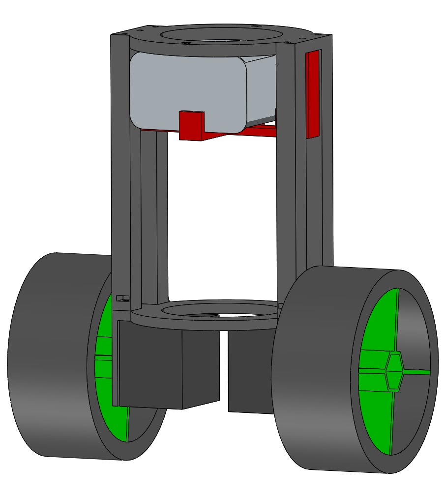
Now that I've got a good handle on the electronics, I switched to SolidWorks for a bit of CAD prototyping. Bbot's chassis is nearly complete. The current design features a NEMA-17 mount, top deck, battery mount, and holes for a wire harness. The only thing I've got to figure out now is where to put the electronics. And for that matter, what form factor the electronics will be in.
So next I'm going to work on planning out the circuitry which should help inform the last component of the structure.
-
Component check!
04/05/2021 at 01:22 • 0 commentsDay 1
It's been about a day since I started working on this project, and I've made what I consider tremendous progress. I've written more than half of the code and wired up most of the components - this includes shift-register manipulation, a clean stepper motor interface, and some well documented helper methods. I still need to get the accelerometer hooked up and coded, but that should be relatively easy considering it's i2c. Then it'll be all about the algorithm. I'm happy to have the boilerplate out of the way.
Next up I'm going to spend some cycles working on the chassis. All code has been checked in to my project github repo, and the CAD files will similarly end up there.
Looking forward to having something pretty to show before too long!