-
1NodeMCU, motor and force sensitive resistor wiring
My circuit is run by a single 12V 5A power supply. A L298N H-Bridge that I had in spare converts 12V in 5V and provides this as input to the ESP8266. This allows me to easily switch on/off the ESP8266 and the stepper driver by a push button.
In my first experiments I used the L298N to operate the Nema 17 stepper. That wasn't a good idea. I burned my ESP8266 when I performed a physical load test to figure out how much kilogram the motor (and driver) is able to lift and hold. So I read a bit about stepper drivers other guys use and gave it a try with the A9488 stepper driver. Even under stress it works like a charm, in the worst case the stepper overruns a step.
The A9488 has a on-board potentiometer that one can use to adjust voltage for the motor. Default setting was already good but not sufficient, in my case a quater turn in clockwise direction gave the motor enough power to lift my 1 kg kitchen skirting board.
Don't forget the electrolytic capacitor (100 µF) to protect the stepper driver from spikes.
![]()
-
23D print the reduction gear
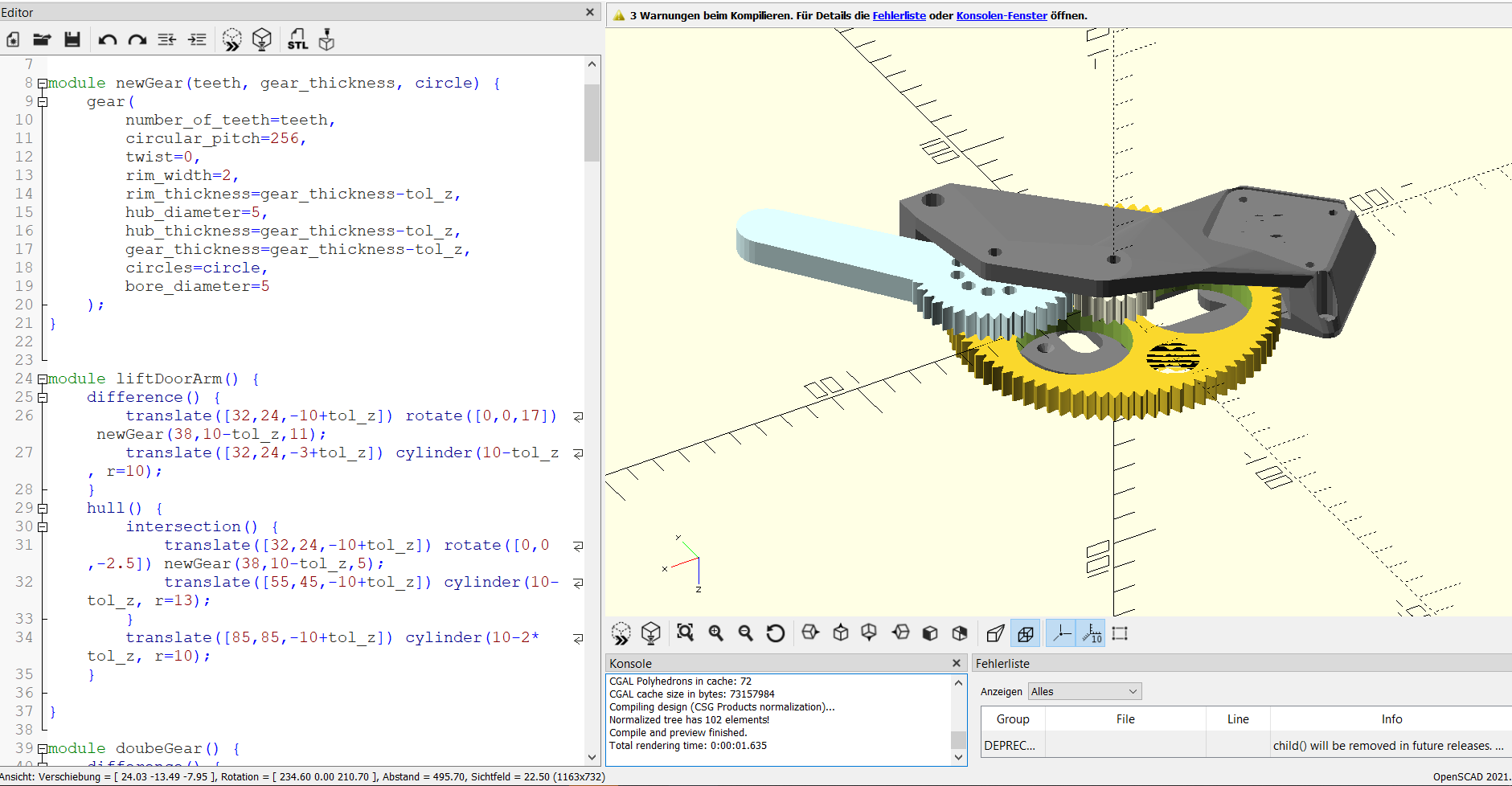
For this reduction gear design I finally did my first steps with OpenSCAD. To get accurate gears I used the MCAD/involute_gears.scad library. For my previous designs I used FreeCAD which was sort of okish for me, but now that I switched to OpenSCAD there is no going back. The reduction gear source file is available on github, modify according to your needs. In addition you might find https://geargenerator.com/ helpful, too.
![]()
-
3Prepare the kitchen skirting board
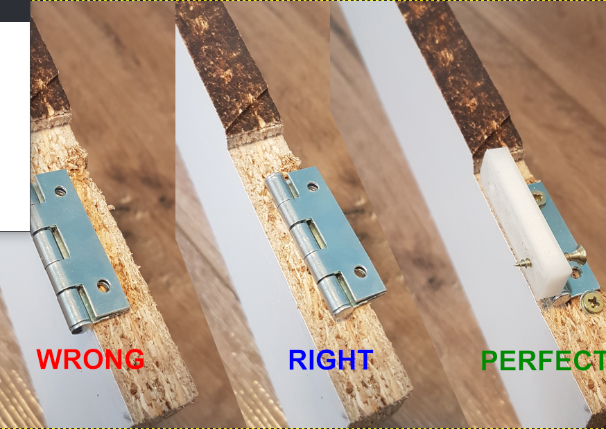
Check the following image on how to install the hings on your kitchen skirting board. If the hing is not centered like in the middle picture, your skirting board won't hang in a 90° angle from your cupboard. However, when the hinge is centered and you place your skirting board not directly at the front of cupboard but a few centimeters back, you need a pad to open the garage door completely without being blocked by the bottom of the cupboard.
Depending on your hinge, you can customize yourself the pad with just a few lines of OpenSCAD code:
difference() { cube([42,11,7]); translate([1,0,-0.1]) cube([40,10,1.2]); translate([8,5,0]) cylinder(h=20,r=1.5,$fn=20); translate([34,5,0]) cylinder(h=20,r=1.5,$fn=20); } -
4Run homecoming observer in background
I've a HP microserver running at home, which I reused to host my tiny nodejs homecoming observer program. I installed it in a unix VM and configured it to run after VM startup.
-
5Install hardware
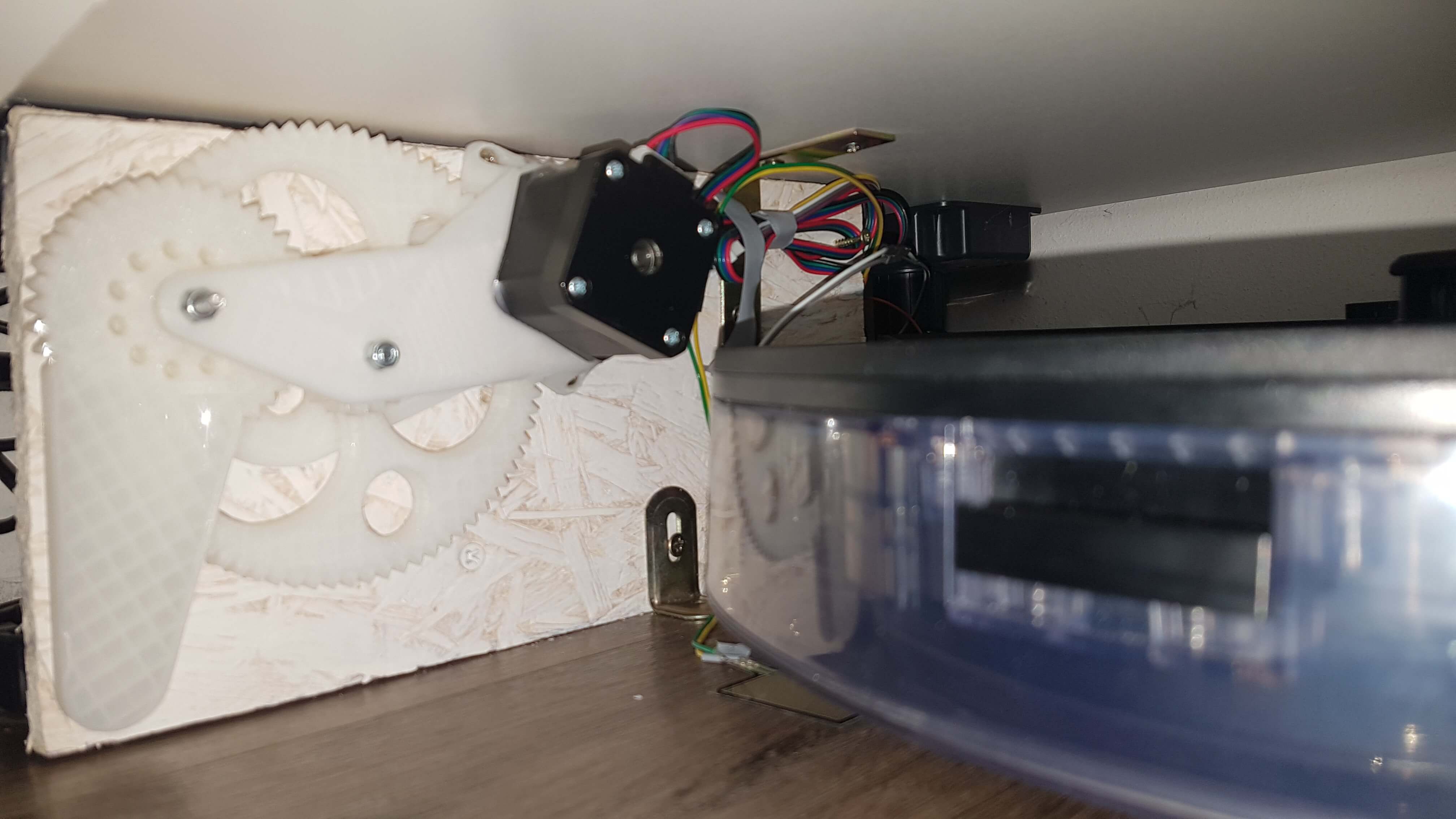
Mount the reduction gear to a e.g. wood construction of your choice. If you don't have much space like me, try to position the stepper motor higher at a height that allows the robot vacuum cleaner to drive
under it. This gives the robot a bit more space to move.
![]()
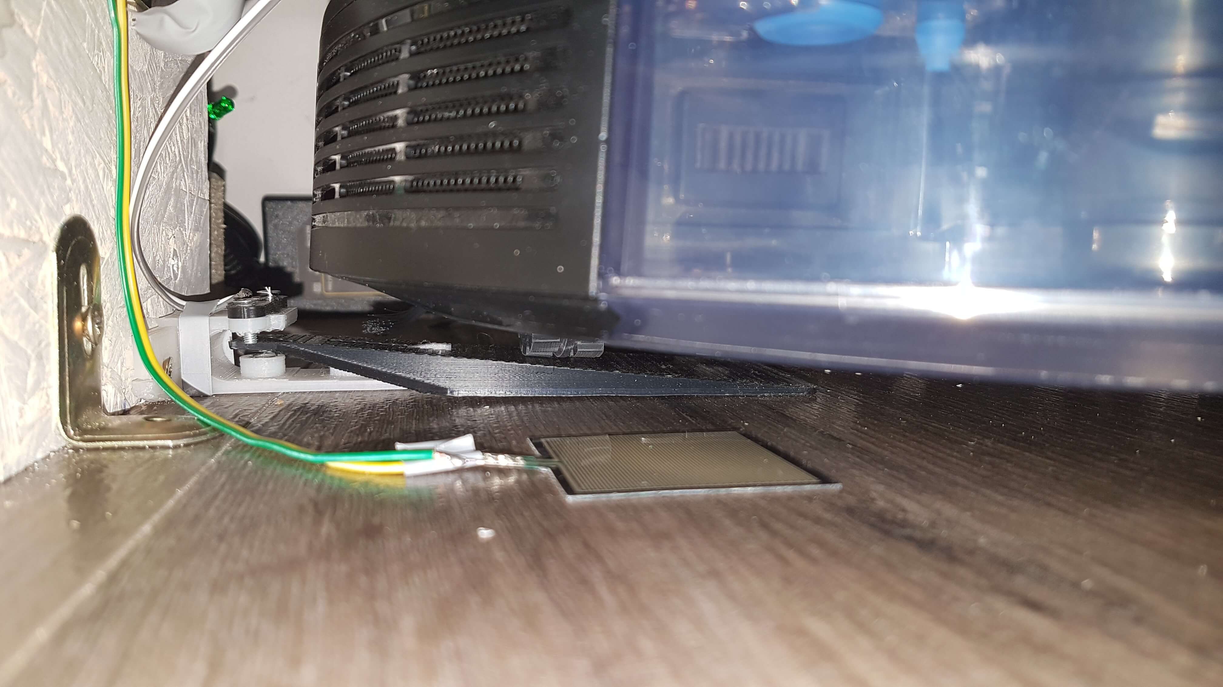
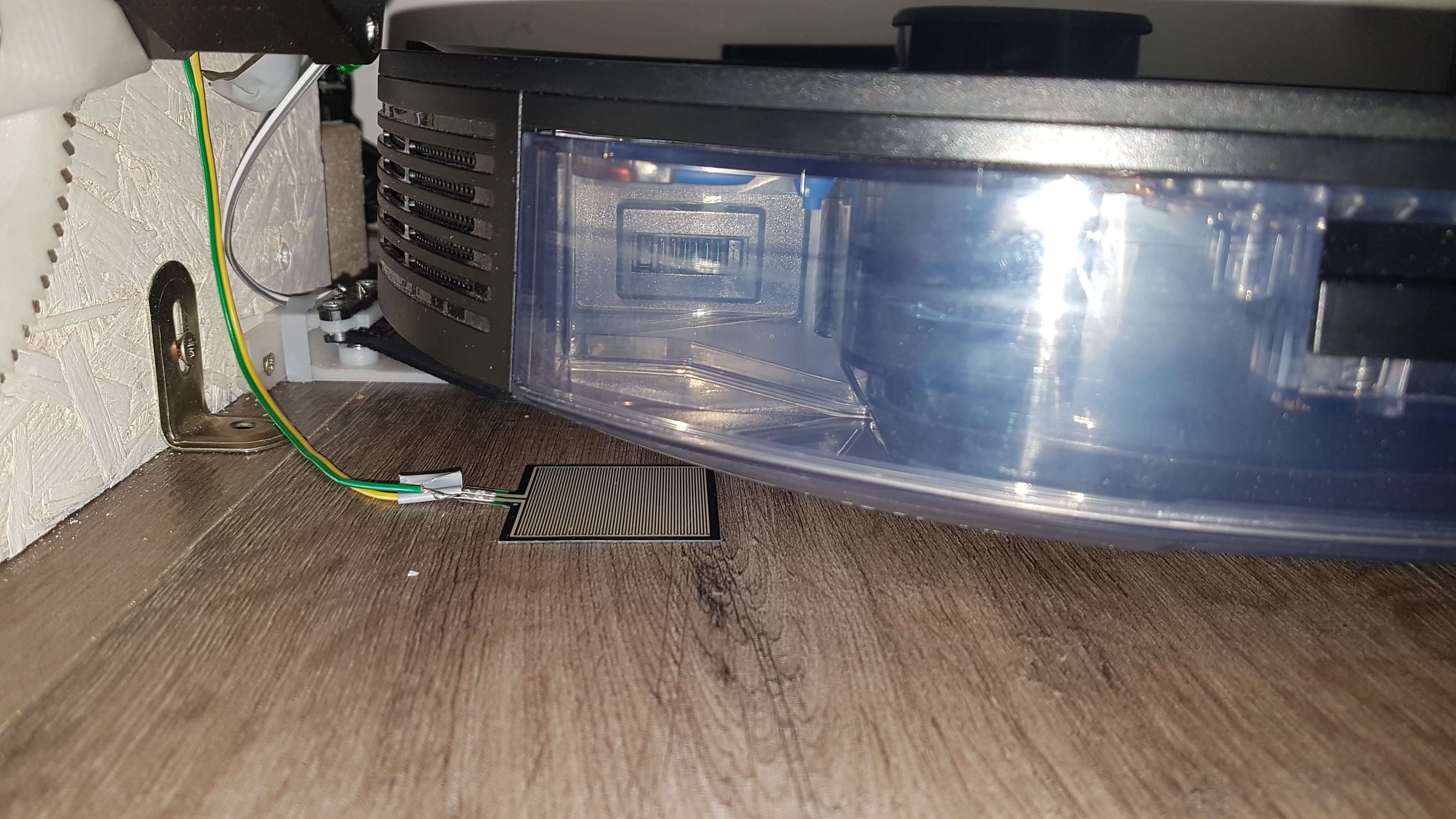
The force sensitive resistor's purpose is to give a signal to the ESP8266 to close the door when the robot is back in the garage. Since the circuit will be powered off as soon as the robot wheel stands on the inverted push button you need to place the FSR needs to be placed a few centimeters in front of the push button. This also depends on the speed of your robot. The slower the robot move towards the charging station, the closer you can put the FSR to the push button. If you put it too close to the button, it could happen that the ESP has not enough time to close the door before it is powered off.
![]()
![]()
Space saving robot vacuum cleaner garage
Automatic control of the kitchen skirting board. Lifts up to 1 kg, zero power consumption on standby.
 MiKa
MiKa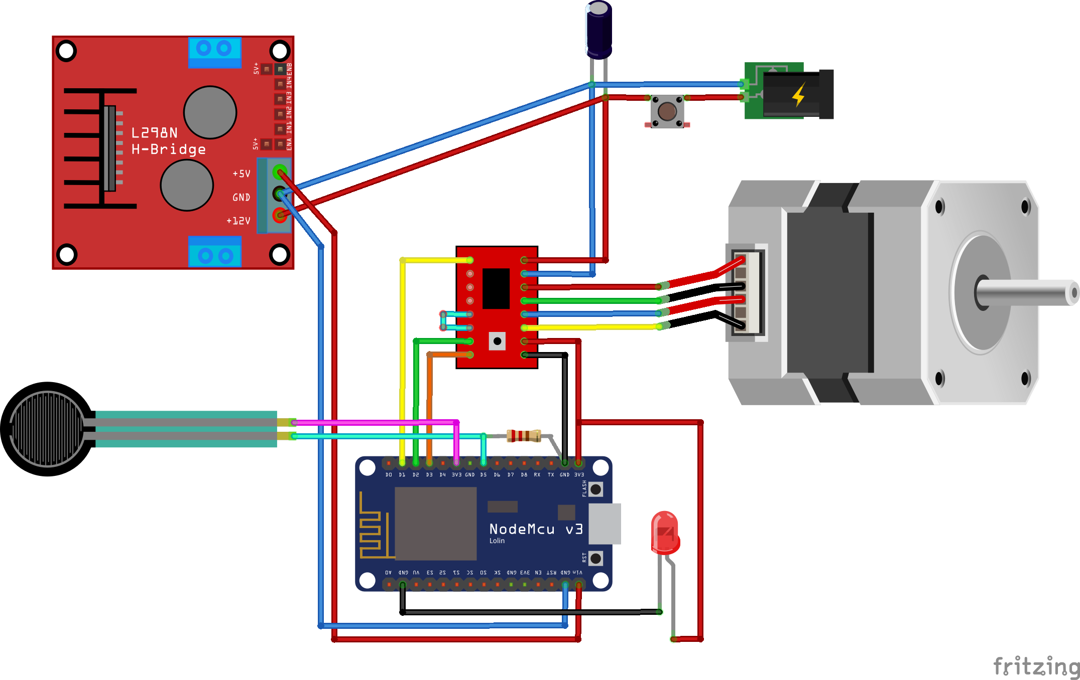
Discussions
Become a Hackaday.io Member
Create an account to leave a comment. Already have an account? Log In.