-
1Order Everything
Omc-Stepperonline: pretty straight forward just sign up, and order.
Maedler: is a site where we order many mechanical parts. These parts are universal and available on many sites. https://www.mcmaster.com/
Bearings: maybe it's locally available otherwise many sites are available for orderings these bearings, same goes for brass melting inserts, cables, and water hose connector.
Sheet Metal: https://metalscut4u.com/carbon-steel, https://www.247tailorsteel.com/nl, https://csmfab.net/
-
23D Print Parts
Some of these photos are of old parts so don't freak out if the given files don't look like them.
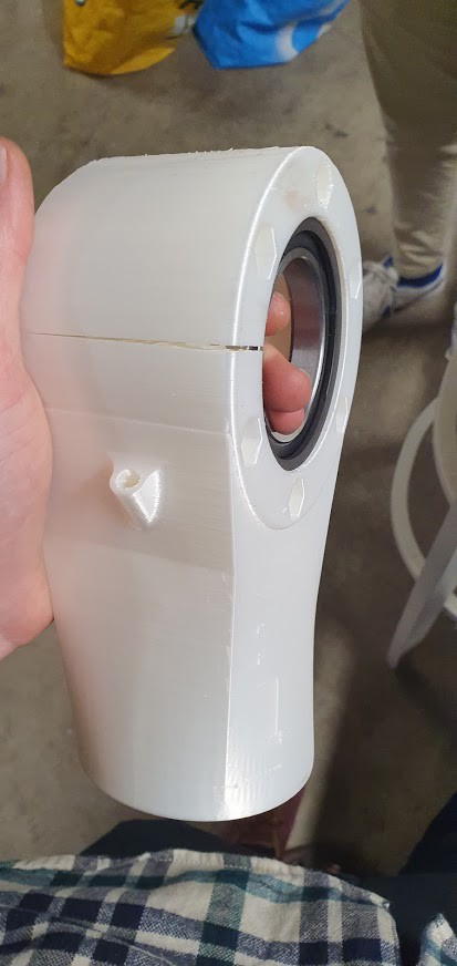
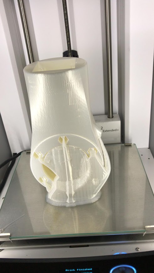
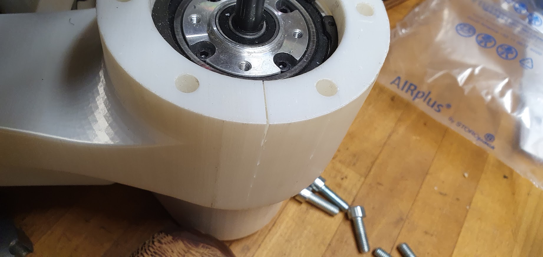
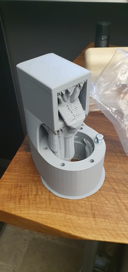
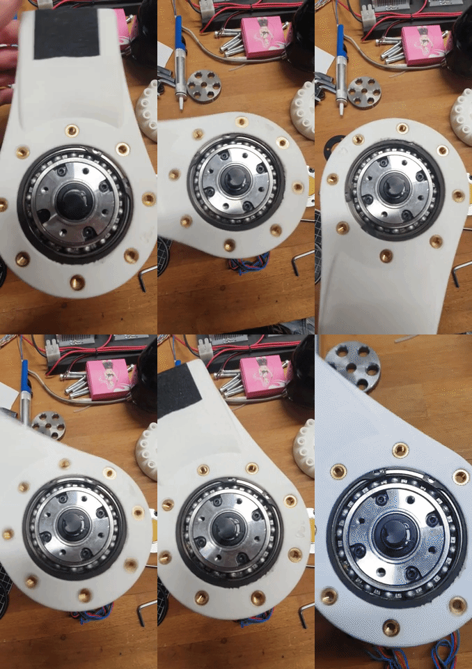
For every joint 3D printed part, you need to make sure that the axis of the circle is always vertical, otherwise the forces of the arm snap the print. Like these photos.
![]()
![]()
![]()
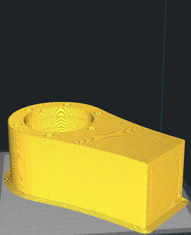
On the photos here under you see how it should be done.
![]()
![]()
You can help see how to orient it by imagining it's a cup holder and the cup inside it must be up.
The tolerances are tight so be careful with warping and all that stuff. 45% infill worked fine for us.
-
3Assembling
Base Assembly
![]()
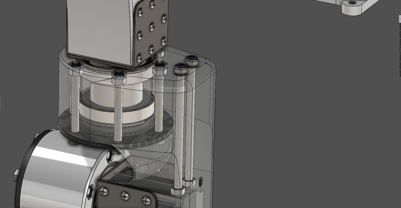
To maximize strength we inserted two 145mm long M8 studs to reinforce a 3D printed part.
![]()
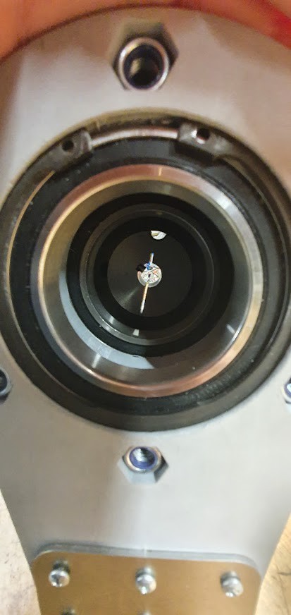
Joints: We tried to minimalize the support but it's hard with the constraints. When you're done printing you remove the support, which can be a real hassle with these designs. You squeeze the bearings in, then you insert the retaining rings. You need to be sure that the retaining rings are secure. To ensure the retaining rings are secure you can compare the shape of the normal retaining ring with the one you're inserting. If the two are symmetrical you can be sure it's properly secure. As long as you don't hear concerning cracks or see concerning cracks.
![]()
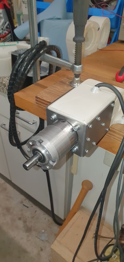
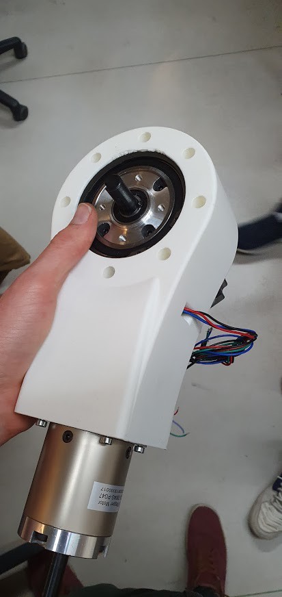
To insert the motor into the printed part with the bearings and retaining rings you need to shave 1mm wall thickness of the planetary reducers to do that you need a lathe. Or find some other method where you can shave 1mm wall thickness of a metal piece.
![]()
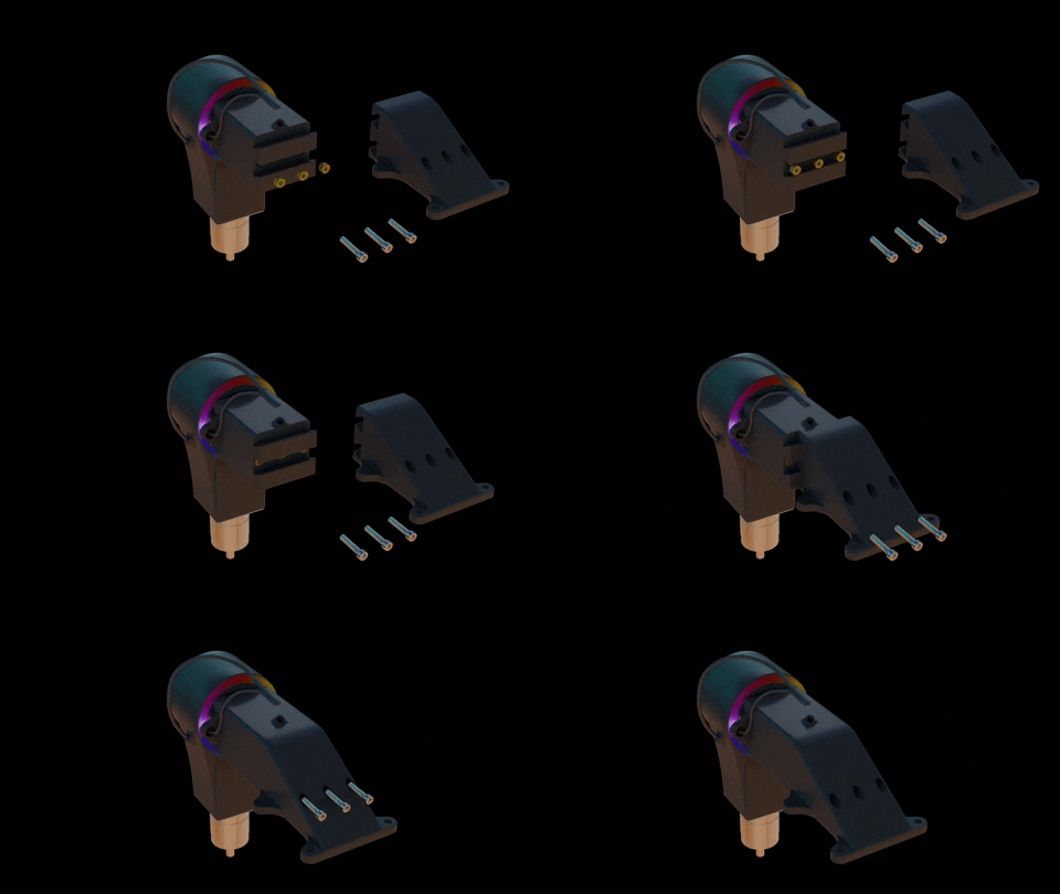
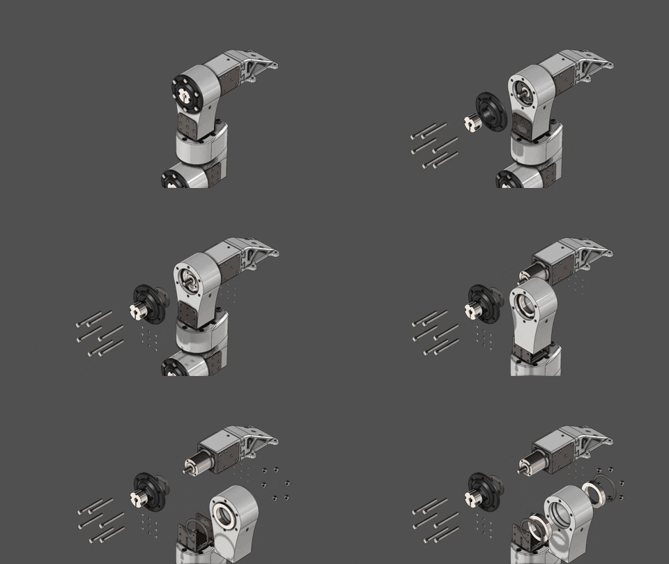
This isn't the best exploded-view for sure. But it gives you a mere idea of how we designed our joints. of course the retaining ring needs to be squeezed to fit inside 3D printed housing.
![]()
![]()
![]()
![]()
![]()
![]()
![]()
![]()
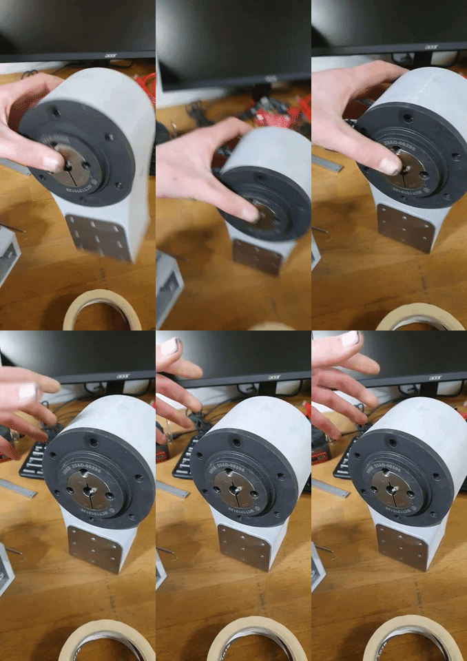
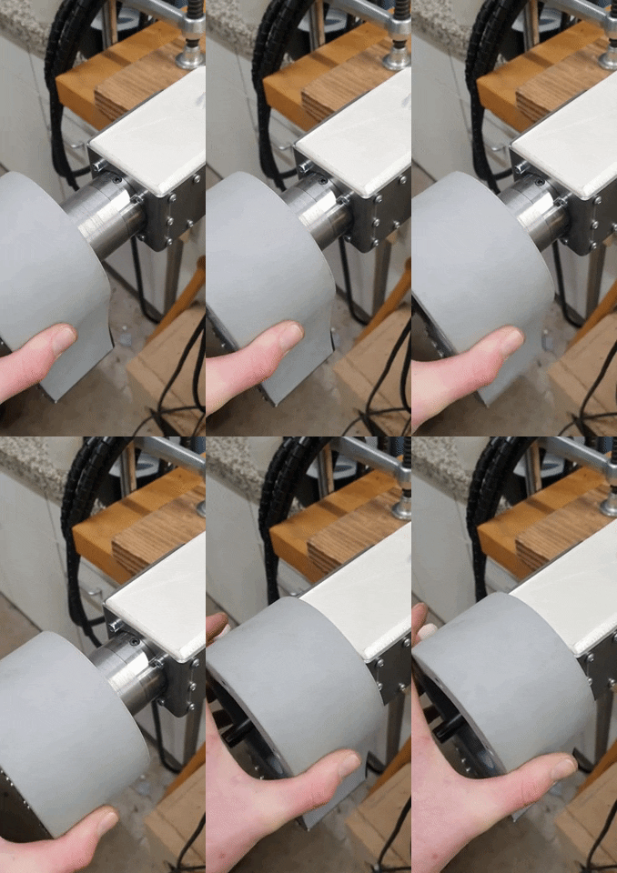
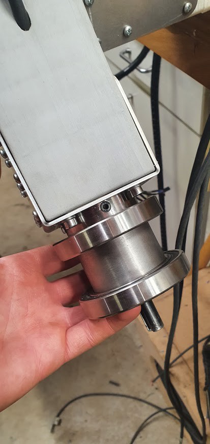
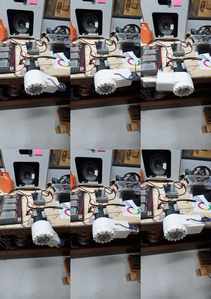
We use both metal and plastic outer taper bush housings, because if you 3D print the outer housing the housing isn't strong enough to clamp to the inner taper bush, which causes additional backlash. That's additional backlash on top of what should be 90ArcMin. What's imported is because all axes have a lot of backlashes the end effector can move in an area of 50x50mm freely. The only way to minimize the result of the huge backlash is by limiting the motion of the arm in a way that gravity pushes the gears in one way. So refraining the motion makes the arm look better and act better than it really is. Almost all of the backlash is a result of the economy gearboxes.
![]()
![]()
![]()
![]()
-
4Wiring
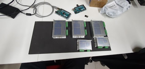
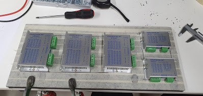
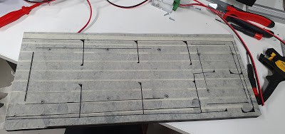
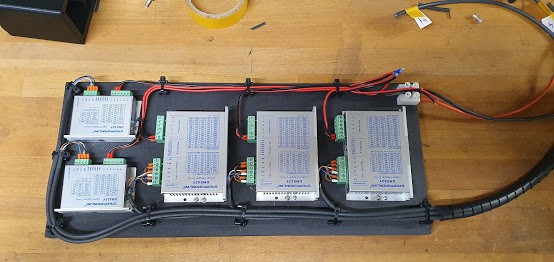
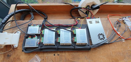
Net power via an emergency switch to the power supply. Power supply to drivers connecting them parallel. connecting the signal cable, wiring the + channel in series to each other. so you can control each driver with a 4 pin wire. wiring the motor wire to the driver is just extending the wire that comes from the motor. Keep in mind that the wire you choose to use for your motors fits in the hole from the 3D print or adjust the design.
![]()
![]()
![]()
![]()
![]()
PROJECT-A
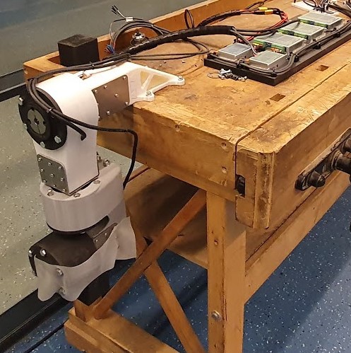
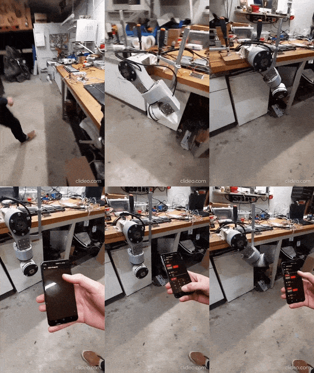
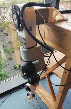
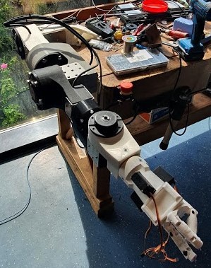
5 Axis articulated robotic arm. Actuated by planetary reduced open-loop stepper motors.
 Sixth_Nassau

Discussions
Become a Hackaday.io Member
Create an account to leave a comment. Already have an account? Log In.