A Lithium-Ion Cell Precharger
Table of Contents
- 1. The rationale
- 2. The problem, "solution" and solution
- 3. The design goals
- 4. Breadboard version and testing
- 5. Testing the initial circuit
- 6. Manufacturing
- 7. The rig assembly
- 8. Closing thoughts
1 The rationale
When working with refurbished Lithium-Ion cells, in particular with attempting to recycle cells from used battery packs you will discover many cells in these packs who are very deeply discharged. It's common to see cells that read a < 1V open-circuit voltage. There can be a number of reasons for this to happen:
- the cell may be damaged in a way that manifests itself as self-discharge
- the cell may have it's CID (Current Interrupt Device) tripped which is an internal fuse in the cell that mechanically disconnects the cell terminals from the case in case of excessive conditions inside the cell, in this case the voltage just reads 0 and presents an infinite internal resistance
- the cell may have been connected to a BMS and not charged for a very long time, this causes the slow leakage current of internal resistances in the BMS to slowly drain the cell
Of those 3 groups the last one is the most interesting to us as these cells can potentially still be reused. It is commonly known that deep discharge is damaging to lithium-ion cells. The cell will loose capacity, the internal resistance will increase. In extreme cases internal shorts can form in the cell which may cause thermal runaway of a cell (fire + smoke). So deeply discharged cell reuse is not without risks and you should always understand what you are doing, monitor the conditions of your cells (current, temperature and voltage) and always have safety features in place. Still for low-current applications there can be a place for a cell that will probably not handle its rated maximum current capacity safely but otherwise is not totally dead.
2 The problem, "solution" and solution
The basic practical issue with deeply discharged cells is that all ordinary chargers have a threshold voltage of a cell which the charger will accept. This voltage is typically around 2.5 or 2.75 V. So if a cell has lower voltage than this the charger may simply refuse to charge it. The solution here is to first trickle-charge the battery until the threshold voltage is achieved and then proceed with charging them with an ordinary charger.
There are numerous videos of this process on youtube often performed by connecting them in parallel to a charged "donor" cell where the current will flow from one to the other charging the weak cell relatively quickly. The thing is this is not what we want to do because the currents can be quite large (> 1 A easily) so we risk damaging the weak cell further. It would be much better to charge it using a small amount of current (< 100 mA) for a longer time.
Another way is to use a normal power supply (for example a 5V one) and connect it to the battery together with a voltmeter. You should be able to watch the battery voltage slowly rise towards the threshold voltage and disconnect it when you are ready.
Both of these approaches make it harder to control the charging current and require you to be constantly alert while you are doing this to disconnect the cell when it's finished trickle-charging or when something unexpected happens.
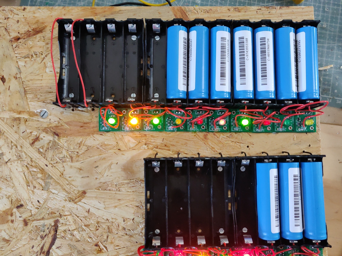
This is where the precharger comes into play. It allows you to perform trickle-charging on cells with relative safety and simplicity. The circut also indicates when the trickle-charging process is complete with a LED so you can connect each precharger to their own cell holder and build a rig that can pre-charge multiple cells at once.
3 The design goals
The design considerations I have laid out for this circuit are the following:
- limited and low charging current to not cause any issues if the cell is shorted or otherwise badly damaged
- cell voltage limit so that overvoltage will not be an issue even when the cell is left connected for a longer amount...
 Enki
Enki