-
Netbooting Alpine Linux and other development
11/15/2021 at 17:29 • 0 commentsFew days ago I promised to write a bit more about new boards and ongoing development. In the weekend I was able to find some time to play with the board and configure software side a little bit. But let me start from the beginning.
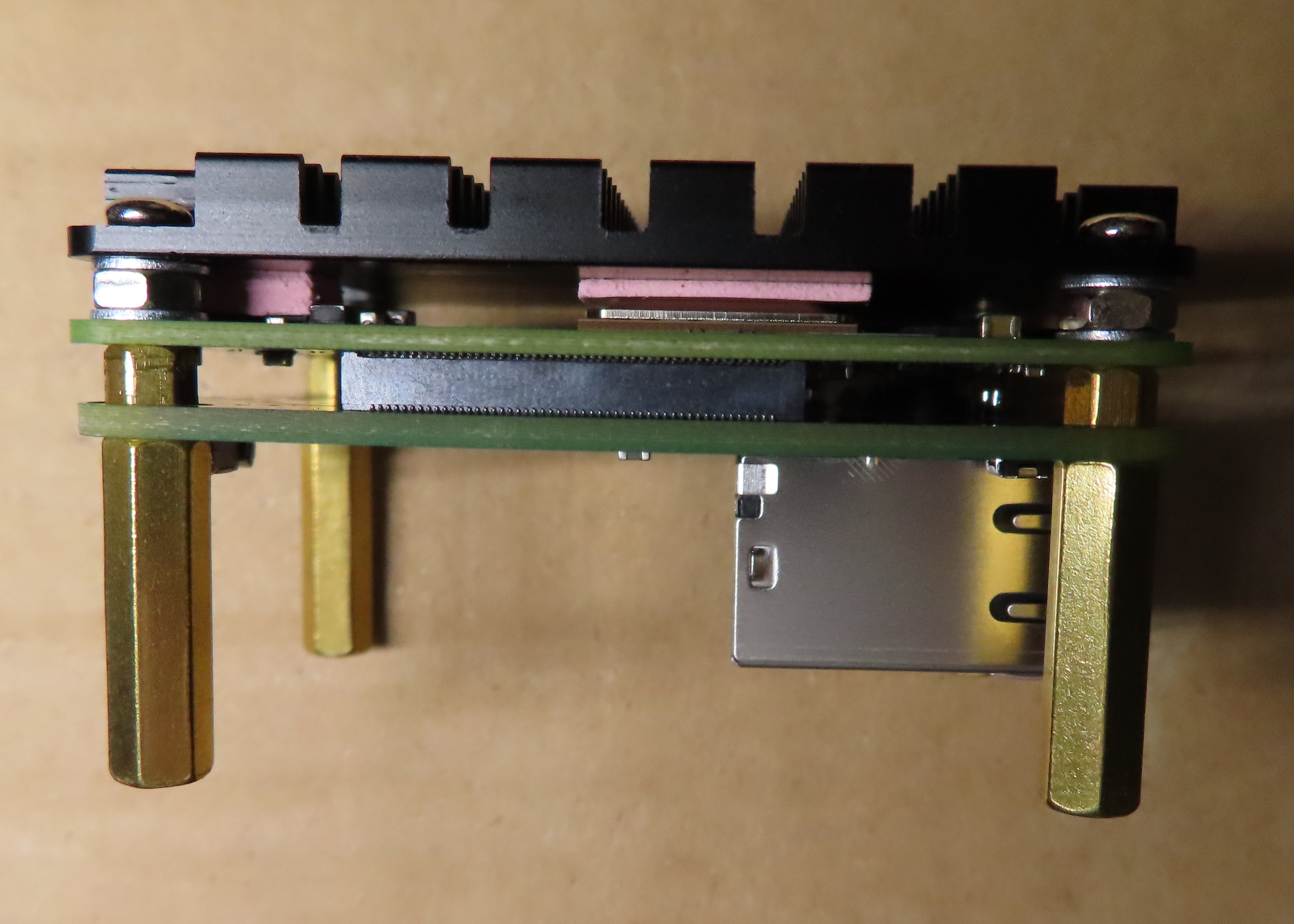
Heatsink
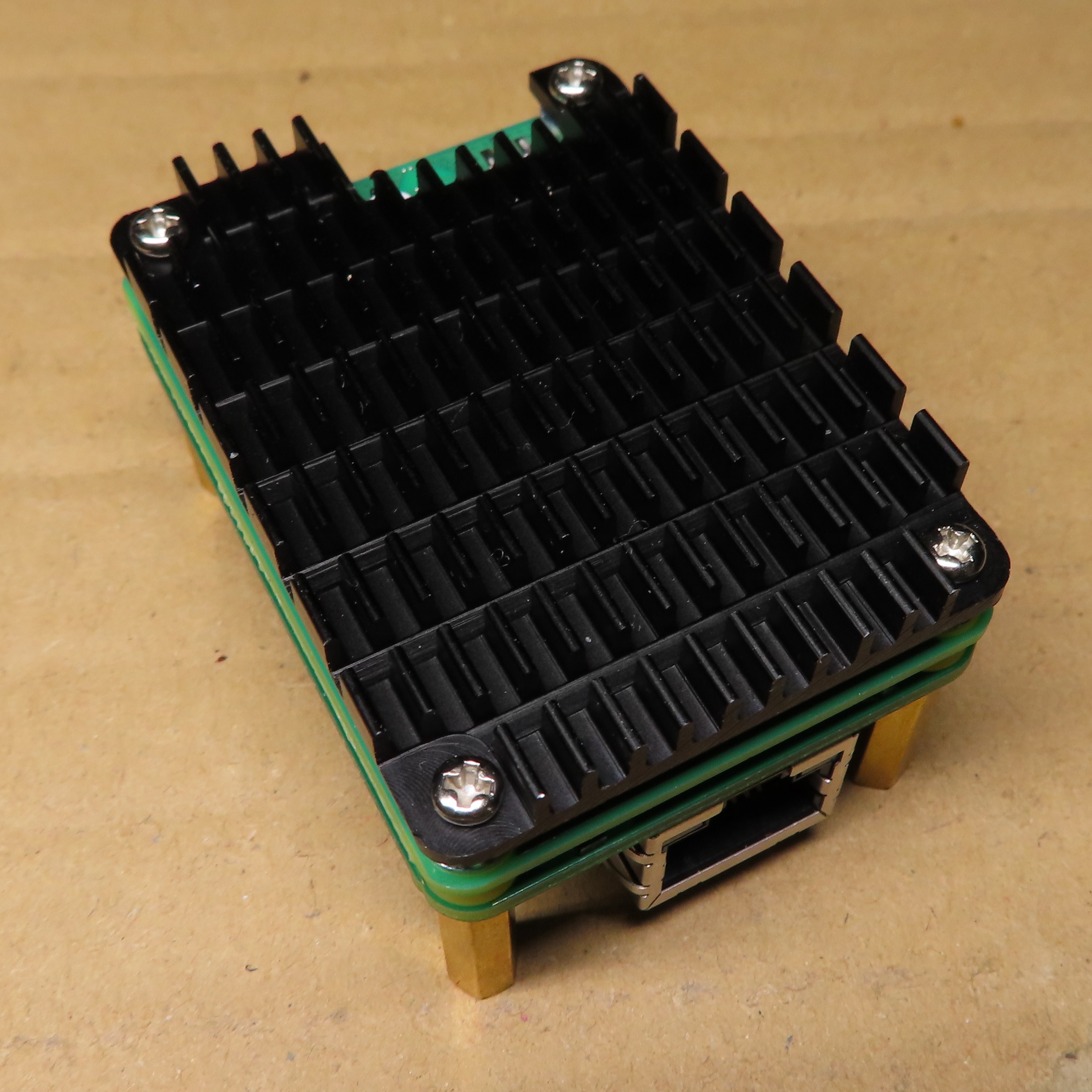
If you have seen the photos in the previous update, then you know I mounted a heatsink to my board. For those interested in buying one themselves, this is a model by Waveshare, precisely this one. It wasn't as trivial as following the manual to make it look like on the photos, because I wanted to still have spacer under the whole setup. I ended up with something like this:
![]()
This whole set of screws, washers and spacers is a mix of Waveshare set and whatever I was able to find. Finally I managed to do it like I wanted, so it is now standing on my desk and at the same time it should be a little bit colder. To be honest, I did not do any stress tests yet, so can't tell if it was worth the effort, but marketing materials looks promising. Maybe if I get more finished software stack, I will do my real world tests, to not make judgements based on stress-ng only, as it is never like the real environment.
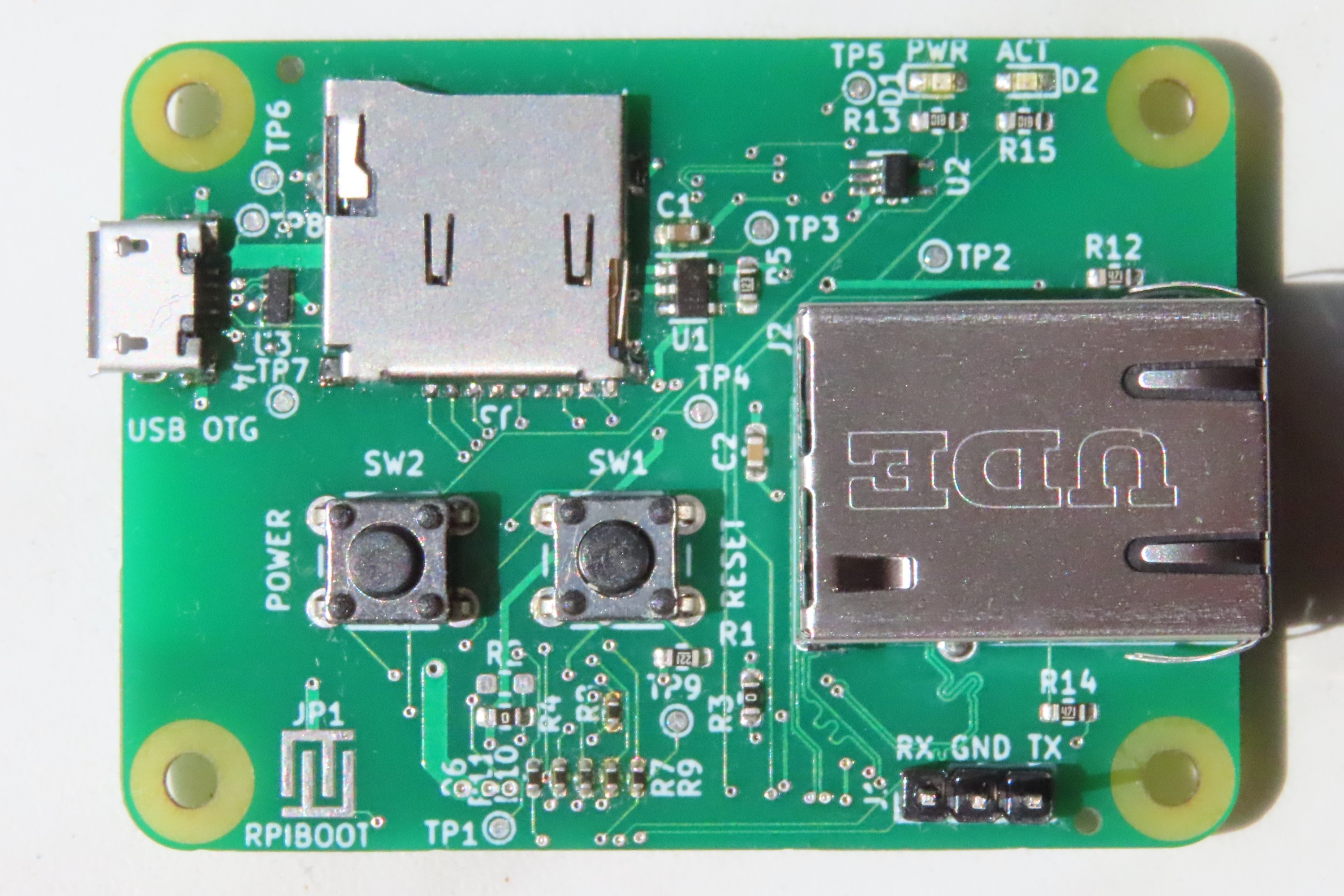
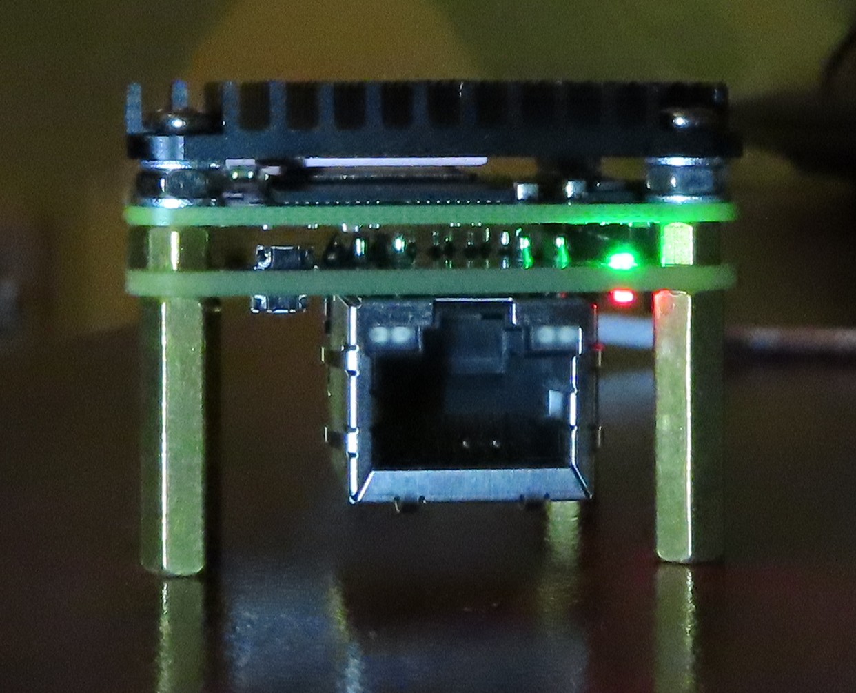
New front panel
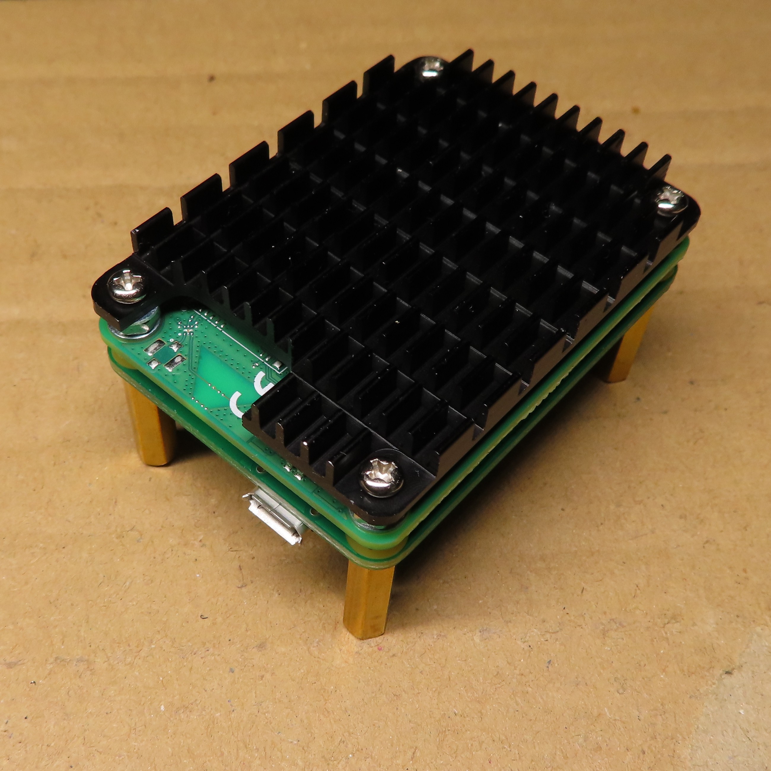
One of the goals of last PCB revision was to make the board more clustering friendly. While you still have to use Micro USB connector on the back, which is unfortunate, but this is how things are for now, everything else is now on a side, that can be called front. So, on this new front there is Ethernet connector, power and activity LED, power and reset buttons. This is how this new front looks like:
![]()
Maybe it is not obvious from this perspective, but these two things left to the Ethernet connector are power and reset buttons. While playing with Alpine I had to use reset a lot and I can already say that it is not easy to use at first, but with help of toothpick, one can get used to it. In final setup, it should not be necessary to use any of these buttons anyway.
Alpine Linux booted from network
Finally, the most important part. My goal, when choosing OS for the cluster, I would like to build was to get something really lightweight. I already knew that there is a distro called Alpine that people use in-container. So, I decided to give it a try. It turned out Raspberry is at the moment supported officially, so no hacking should be needed to make it work. On official website, one can download special package for Raspberry Pi. Despite that official support, it wasn't immediately ready to serve via TFTP, so I had to make some small adjustments:
- First of all I extracted alpine-rpi-3.14.3-aarch64.tar.gz package to tftp directory, so my dnsmasq.conf could serve it. You can use the same config that I used for ordinary Linux before (don't remember whether it was Arch or Raspberry Pi OS, sorry :) ).
- In the extracted package, two files require modification. First is config.txt to enable UART, as SSH will not work at this point. So this is what needs to be appended to [all] section:
dtoverlay=disable-bt
- Second is cmdline.txt, as it is not configured for netboot, which is no surprise, as this is not the default way to boot OS. Try something like that:
modules=loop,squashfs console=serial0,115200 ip=dhcp modloop=http://10.42.0.1:8080/modloop-rpi4 alpine_repo=http://10.42.0.1:8080/apks apkovl=http://10.42.0.1:8080/localhost.apkovl.tar.gzNote that 10.42.0.1 is my Linux system that will serve as TFTP/DHCP server, as well as HTTP server to give Alpine-specific files. By the way, its nice, you don't need NFS at all, when netbooting Alpine, which is rather unique function.
Last thing to prepare is public_html that will serve those 3 files (apkovl will not exist for now, we will add it later). Modloop files can be found at tftp/boot/ directory, so let's copy them to public_html. apks are directly in tftp, copy them, too.
Finally we have to start DHCP/TFTP and HTTP servers:
sudo dnsmasq -dC dnsmasq.conf -i enp1s0 &
darkhttpd public_html &
This makes them run in background of current shell, so not exactly a permanent solution, but good enough for now :)
And we are ready to go, connect Ethernet cable, configure network on server side and plug power cable to uCM4 (provided you already have netboot enabled, otherwise, go to my previous tutorial).
- Wait a bit and you should start seeing stuff happening on dnsmasq, then UART and finally darkhttpd. A minute or so and login prompt should appear on UART. root does not have password for now. You can set your system up by calling setup-alpine, choosing your preferred config, then exporting LBU_BACKUPDIR variable to anything, like /tmp directory and calling:
lbu ci
to save your settings. As a result apkovl file appeared in the directory you chose, so now you should be able to transfer it to your server and place in public_html with name set in cmdline.txt. You are set! Next time you boot your system, you should have it configured.
Cluster
My final attempt was trying to setup master node for my cluster. And with this one, I failed. I was able to configure repositories in Alpine and even I had docker up and running. This is surprising for me, as I tried that on Arch and it was hanging on docker run, whatever I did. Here it was all fine. But installing kubeadm lead me to the ENOSPC error. It turned out that I ran out of disk space, which was tmpfs filesystem, in my RAM. I was using 1 GiB CM4, so there was no hope for me at this point, but I did not give up yet. Just for science :) I remounted / to give it astonishing 768 MiB of disk space. It worked and kubeadm with all dependencies installed, but trying to create master node gave me information that 2 GiB of free RAM is minimum for Kubernetes. Obviously, I ignored this error, but few seconds later I got an error from docker. Closer look at that issue revealed that while pulling Kubernetes image, I was left with 10 or so MiB of disk space and a bit more of RAM, so it is practically impossible to succeed with 1 GiB module. 2 GiB is rather unlikely to start Kubernetes, too, especially due to the fact that RAM is used as disk, too, so everything that is running is duplicated.
As a result, I bought one 4 GiB CM4 Lite module, which should arrive tomorrow, as I am lucky that distributor in Poland just got new batch of them few days ago and they are still there.
NFS root under Alpine
There is one more option to decrease RAM consumption by the system - mounting root as NFS. I even tried that in the weekend, but it did not work out-of-the-box. It seems that this is a kind of experimental feature and what's more, I have issues with regeneration initramfs, so no success for now. I should be able to get back to the topic next weekend, with my shiny new CM4, unless 4 GiB turns out to be enough. But I doubt it will :)
Conclusion
So, this is all for now. Hope that somebody will find my Alpine guide useful. For anybody else, there is one lesson to learn for here - do not buy 1 GiB CM4, if you want to build your own cluster on top of that. Buy 4 GiB instead, or 8 GiB, if anyhow you have access to it in a reasonable price.
-
v0.2.0 boards arrived and work!
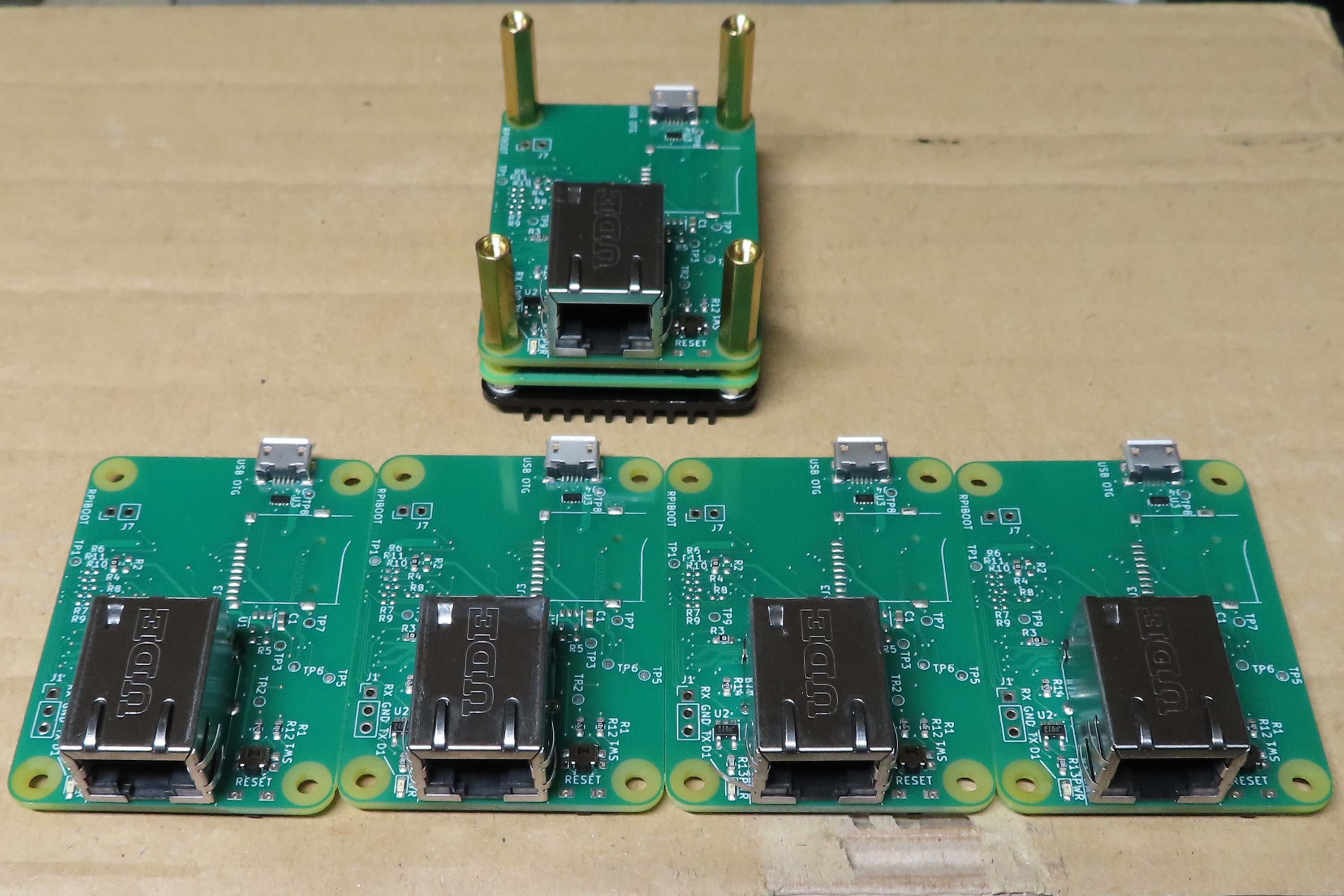
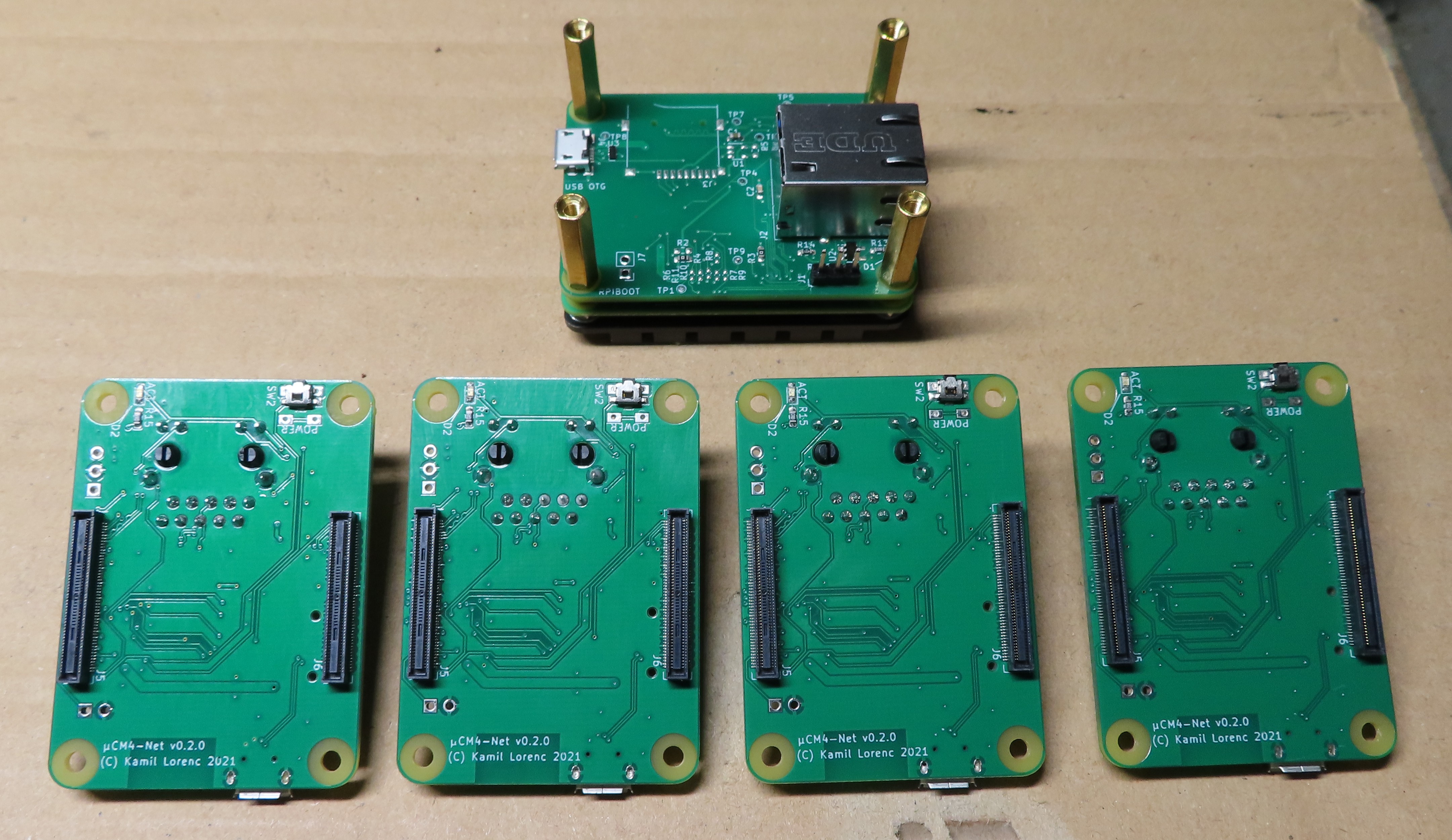
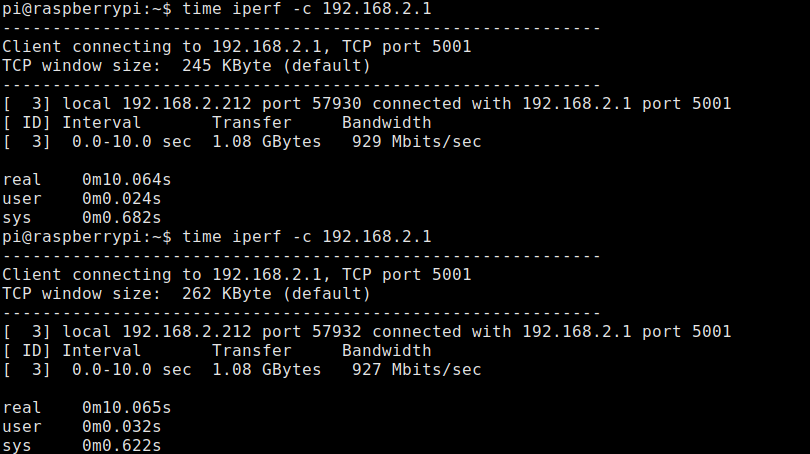
11/04/2021 at 18:08 • 0 commentsToday, finally, after more than a month (last update was September 13) I received a package with 5 boards in 0.2.0 revision. I just finished testing one of them and till now everything works perfectly fine. I hoped for earlier arrival, but Chinese holidays in early October caused delay even to factory estimates. Fun fact is that I chose railway parcel as a shipping option, so now I know that maybe it is faster than ship, but air mail still wins in terms of time. Anyway, they are finally on my desk, so expect some news in the coming days. For now I can show you short gallery and obviously Ethernet benchmark, as this board is all about Ethernet, so it would make no sense without maximum throughput that BCM2711 can give me. Here it is:
![]()
![]()
And below should explain why fifth board looks so weird:
![]()
![]()
Finally promised iperf results to my laptop. By the way the same PC shared TFTP and NFS to netboot CM4 under test, as obviously boards came with no microSD connectors.
For today this is all I have. I hope in the coming days I will be able to play with the boards a bit more.
-
New board revision, almost ready for manufacturing
09/13/2021 at 15:30 • 0 commentsFor the past weeks I got couple of questions about ability to buy a piece or two of my boards. I decided that I could try myself at manufacturing and offer such option in near future. At the moment I would like not to disclose any details as this is in quite an early stage. But today is for me quite a huge step in that direction. I ordered test batch of 5 pieces, fully manufactured, so I will not have to assemble anything myself. If this works, I will be ready to order any amount at the same factory.
These boards are by the way in new version - 0.2.0, which, as numbering suggest, has way more significant changes than introduced with 0.1.1. On the other hand there is IIRC no modification to schematics, so less likely to make mistake that will make them unusable. This means that I am quite optimistic about this design. Still I am not so sure about all the other files I had to prepare for factory, as I am not very experienced with that, but we will see if this worked :)
Getting back to new board. changelog is on Github, so those interested can read it and of course there is also full git log for real nerds :) Most visible change in this version would be replacement of buttons with smaller SMD ones and moving them near the same edge that is already occupied by Ethernet connector. The idea with this, and also moving LEDs to the same side, was to make it easier to handle in clusters, where I can imagine it is desirable to have full control of the board, while seeing only front side. This should be now possible. There are also a couple of other modifications, at least one of them as a result of chip shortage, so those willing to make board themselves should ensure they read BOM of the right version, when ordering parts. This is already updated for 0.2.0, here on Hackaday.
And, after all this good news, there is still one bad news - PMICs, that are needed for microSD are still unavailable at usual, trusty suppliers, so there is no chance to handle Lite CM4s with SD boot - sorry, but there is little I can do. Having said that, I should mention that I am somewhat affected by that, too, as I had to order assembly without microSD support. Now, if I decide to start manufacturing, I would have to decide whether I should wait, or manufacture without microSD, so if you are interested in getting uCM4 for yourself, let me know your opinion. You can write comment, or contact me directly, so I will know better people's expectations and will be able to make the right decision.
Anyway, next month will be just waiting, also for me, as there is not much to do in this topic before getting the hardware. And factory claims it would take them a month to assemble. And then a week or two have to be reserved, before getting the package at my door. So, if you can't wait to hear next update, let me know and spread the word. All this makes it more likely to get this board on your shelf!
-
Ethernet works again, even with netboot/PXE
08/07/2021 at 19:09 • 0 commentsToday I have two small updates and two good news at the same time. I fixed Ethernet on my v0.1.1 board and just finished configuring PXE with this board. At the moment I am finalizing tutorial on how to netboot CM4 connected to uCM4, as it turned out to be less obvious than I thought.
Getting back to Ethernet issues, this indeed turned out to be soldering problem. After reflowing both connectors, problems disappeared. Fun fact is that I was forced to do that, because I destroyed high speed connector few days ago, when disconnecting CM4. It turned out to be soldered so badly that I broke it, instead of disconnecting. Anyway, this forced me to fix the thing and in the meantime I checked that Hirose connectors could still be fixed, when pins fall off the connector chassis. And finally I learned how to solder them quickly and successfully, so if you are interested in getting some advice, let me know and I can consider describing it from newbie perspective (it seems that I am still lacking experience in soldering).
Expect tutorial in coming days!
-
Netbooting Compute Module 4 in uCM4 carrier
08/06/2021 at 17:08 • 0 commentsuCM4 was designed as a network device. It has Ethernet connector, which is the most important interface to outer world. And these days many devices, including our PCs can boot directly from network using thing called PXE. For uCM4 PXE would make Micro SD connector unnecessary. Luckily for us, for quite some time Raspberrys also can boot themselves from network. CM4 is not an exception here. But unlike ordinary Raspberry Pi 4, it is a bit more complicated. Let me present how to achieve that with CM4 and uCM4. I would not be surprised, if you got here while looking for a way to do that with CM4 and official CM4IO, so I will try to mention the differences between uCM4 and CM4IO in that matter. Enough of this introduction, let's start!
What you need
Basically, there are few Git repos to clone to allow you to get started. Clone them by issuing following into your system (this does not necessarily has to be Raspberry and keep in mind that for uCM4 you will have to be able to power whole system from that device, so my advice is to use PC, or alternatively device with active USB hub in the middle):
git clone https://github.com/raspberrypi/rpi-eeprom.git
git clone https://github.com/raspberrypi/usbboot.git
If using uCM4, you also gonna need tweezers, or something similar to short JP1 jumper. I know, this is one of the not-so-successful parts of the design and is going to be subject to change in future.
What's more, on the system that will serve as server for Raspberry to communicate with you have to install DHCP, TFTP and NFS servers. In case of Arch Linux these can be provided by dnsmasq (DHCP+TFTP) and nfs-server (NFS). In other distros names should be similar.
Getting software ready
Fortunately programs in rpi-eeprom repo are in fact scripts, so nothing to do there. But in usbboot, you actually have to compile. Luckily this is as simple as calling:
make
As a result you should get rpiboot binary directly in repository root directory.
Getting right EEPROM firmware image
This is harder part. From what I know, it is not possible to simply change configuration in EEPROM. You have to flash full firmware image with changed configuration. What I did was to simply copy recovery firmware from usbboot repo, but in fact you can use any version from rpi-eeprom repo. The one that I chose is pieeprom-2020-10-02.bin, so this is how I will refer to it later.
Preparing configuration
As you have your pieeprom image, you can go to usbboot repo and create new directory for our network configuation. Copy your EEPROM image to this new directory. Don't change the name for now, we will make use of this improper name later. You will also need bootcode4.bin from recovery as first stage bootloader, I guess. Now it would be nice to get current boot.conf from CM4 that we are going to reconfigure. While in Raspberry Pi OS, you can simply call:
vcgencmd bootloader_configAnd save the output as boot.conf of your PC. You should get something like me:
[all]
BOOT_UART=0
WAKE_ON_GPIO=0
POWER_OFF_ON_HALT=1
DISABLE_HDMI=0
BOOT_ORDER=0xf41
At this point the only change for us to do is to replace 0xf41 with 0xf21. Why? Here is the documentation from Raspberry Pi Foundation. Basically this 4 meant USB-MSD and 2 means NETWORK, so we create order like SD->NETWORK->RESTART.
Updating EEPROM image with new config
We have our configuration, but not in a file used by rpiboot. So, we have to insert it, yet. And this is why we really needed rpi-eeprom repo. First, we need to add it to our PATH:
export PATH="$PATH:/path/to/rpi-eeprom"Then we have to call rpi-eeprom-config to modify pieeprom.bin:
rpi-eeprom-config --config network/boot.conf --out network/pieeprom.bin network/pieeprom-2020-10-02.binThis creates the file that rpiboot expects - pieeprom.bin. Finally, we need to create signature for our image. Let's start by copying template from recovery directory. Then call sha256sum to see current hash:
cp recovery/pieeprom.sig network/
sha256sum network/pieeprom.bin
Replace hash in the first line of sig file with what you got, so it looks more or less like below:
384a24cbb35d648de76fb19f5bef51b895e4a3d35ef0692f85045e5e6a6ec238
ts: 1628266219
That's it. We are ready to go!
USBbooting uCM4
Now you have to get your CM4 into the state, where it is connected to power, but turned off. In theory it is possible to short JP1, while connecting USB, but it is way easier to short it, then while keeping it short, simply push POWER button. You should immediately see that activity LED is not blinking which means that most likely it succeeded. We can verify that we indeed shorted it in the right moment by checking lsusb on PC. One new device should appear:
Bus 001 Device 017: ID 0a5c:2711 Broadcom Corp. BCM2711 BootThis means that we have BCM2711 in mode called rpiboot. This allows to boot it with rpiboot tool via USB connection to our PC.
In this step users of CM4IO board are more lucky, as CM4IO is development board, so there is goldpin jumper for that and it is clearly described on silkscreen:
So, if you are lucky to have CM4IO, you just put a jumper to first position of J2 connector, connect to power and should be ready for flashing.
Flashing
Now what is left is just flashing EEPROM:
sudo ./rpiboot -d network
Following output should appear on Linux console:
Loading: network/bootcode4.bin
Waiting for BCM2835/6/7/2711...
Loading: network/bootcode4.bin
Sending bootcode.bin
Successful read 4 bytes
Waiting for BCM2835/6/7/2711...
Loading: network/bootcode4.bin
Second stage boot server
Loading: network/pieeprom.bin
Loading: network/pieeprom.bin
Loading: network/pieeprom.sig
File read: pieeprom.sig
Loading: network/pieeprom.bin
File read: pieeprom.bin
Second stage boot server done
And this is what you should see on UART:
SIG pieeprom.sig 384a24cbb35d648de76fb19f5bef51b895e4a3d35ef0692f85045e5e6a6ec238 1628266219
Read pieeprom.bin bytes   524288 hnd 0x00000000 sha256 384a24cbb35d648d
Reading EEPROM: 524288
Writing EEPROM
.................................................................................+..............................................
Verify BOOT EEPROM
Reading EEPROM: 524288
BOOT-EEPROM: UPDATED
This means that we are fine!
Verifying
Previous step should leave you in blinking LED state, so you have to reset CM4. Do not try PXE, yet and leave SD card on its place.
Before actually trying netboot, let's verify that we have network boot enabled by calling again:
vcgencmd bootloader_configAs a result, you should now see:
[all]
BOOT_UART=0
WAKE_ON_GPIO=0
POWER_OFF_ON_HALT=1
DISABLE_HDMI=0
BOOT_ORDER=0xf21
Netbooting
Now, we can go standard path, as with any other device that we want to netboot. For this you could try to follow official tutorial for Raspberry Pi, but my opinion is that it is overengineered, if the only thing we want to do is to test things out. There are only two important configuration points to make it work. First is to setup DHCP and TFTP server together, as both are delivered by dnsmasq. Second is to start NFS server to share root filesystem.
DHCP+TFTP
First thing that Raspberry Pi will try after bootup is getting IP address. For this you can obviously go official way and set connection up on other Raspberry, or you can make it simpler. My idea is to use ordinary PC as a server. Other option that I can think of is to use home router. But for this, that can't be an ordinary, cheapest router that you could get on ebay. It won't work that way. Mikrotik for sure could do that as well, if only you can connect USB stick to it. Anyway, getting back to my setup. What I want to do is to unplug Micro SD card from uCM4, plug it into PC and use it directly.
For this, we need Ethernet connection active with static IP address. NetworkManager could do that, netctl too, so I won't describe that here.
I assume that I have boot partition of my Raspberry at /mnt/boot and rootfs at /mnt/rootfs. There is one small problem in using boot directly. We need to modify cmdline.txt, so it will use NFS, instead of rootfs partition. If we do that directly, we would have to use NFS even if we plug SD card back into uCM4. So it is better idea to mirror boot partition, let's say into /tftpboot:
mkdir /tftpboot
cp /mnt/boot/* /tftpboot/
For now cmdline.txt could stay unmodified, it will be needed when we have NFS share.
Now create dnsmasq.conf file and put something like that inside
port=0
dhcp-range=192.168.2.100,192.168.2.254
log-dhcp
enable-tftp
tftp-root=/tftpboot
pxe-service=0,"Raspberry Pi Boot"
It is important to have dhcp-range within range defined on your Ethernet connection. Otherwise, it fails.
Now the server could be started with:
dnsmasq -dC dnsmasq.conf -i eth0Provided that you are in directory, where your dnsmasq.conf is and you have root privileges.
And basically this is it. At this point you should be able to boot your kernel by simply powering CM4 on. In dnsmasq logs, you should see TFTP requests for Raspberry Pi boot files. Obviously this will stop at mounting rootfs:
[ 3.058370] Waiting for root device PARTUUID=12345678-01...cmdline.txt
Now it is time to adjust kernel arguments to use NFS instead of SD card. By default it is set like:
console=serial0,115200 console=tty1 root=PARTUUID=01234567-02 rootfstype=ext4 elevator=deadline fsck.repair=yes rootwaitWe need to change to something like:
console=serial0,115200 console=tty1 ip=dhcp root=/dev/nfs nfsroot=192.168.2.1:/mnt/rootfs,vers=4.1,proto=tcp elevator=deadline fsck.repair=yes rootwaitDon't forget to adjust IP address and location of rootfs!
NFS
Last thing is to set NFS up. This is as easy as modifying /etc/exports on your server and adding export like this:
/mnt/rootfs *(rw,sync,no_subtree_check,no_root_squash)
Then you have to reload those changes into NFS server with:
sudo exportfs -arvAnd start NFS server. On Arch it is like that:
systemctl start nfs-server
But could be slightly different on other distros, so refer to their documentation, especially if your distro did not migrate to systemd!
Last thing that will prevent your Raspberry from booting is /etc/fstab, which still will attempt to mount SD card and will fail after timeout period. My workaround, if you want to use exactly same image for both PXE and SD boot is to move fstab file to /boot and create symlink from /boot/fstab to /etc/fstab. This way we could have two different fstab files - one on tftpboot, one on SD card's boot partition. This could be done with:
cp /mnt/rootfs/etc/fstab /mnt/boot/
cp /mnt/rootfs/etc/fstab /tftpboot/
ln -sf /boot/fstab /mnt/rootfs/etc/fstab
Finally, we can change just /tftpboot/fstab and comment out SD-related entries:
proc            /proc           proc    defaults          0       0
#PARTUUID=12345678-01  /boot           vfat    defaults          0       2
#PARTUUID=12345678-02  /               ext4    defaults,noatime  0       1
# a swapfile is not a swap partition, no line here
#   use  dphys-swapfile swap[on|off]  for that
At this point, we can attempt booting CM4 with Ethernet connected, all servers running and connection set up on server side.
Actually this makes fstab to be unreachable in Raspberry Pi OS, when netbooted, but despite that, it works. For proof of concept it is enough. For the final solution, not really. But for final setups, I can imagine that one wants to have separate images for netboot and SD boot anyway. Having it common is only an advantage for testing.Now, when powered your CM4 should start from network and you should clearly see in logs of dnsmasq, CM4 UART, or Wireshark that it did. That's it!
-
Build completed
07/31/2021 at 12:12 • 0 commentsYesterday I was able to finish soldering the board. Here you can see it during first test with CM4 connected to power supply:
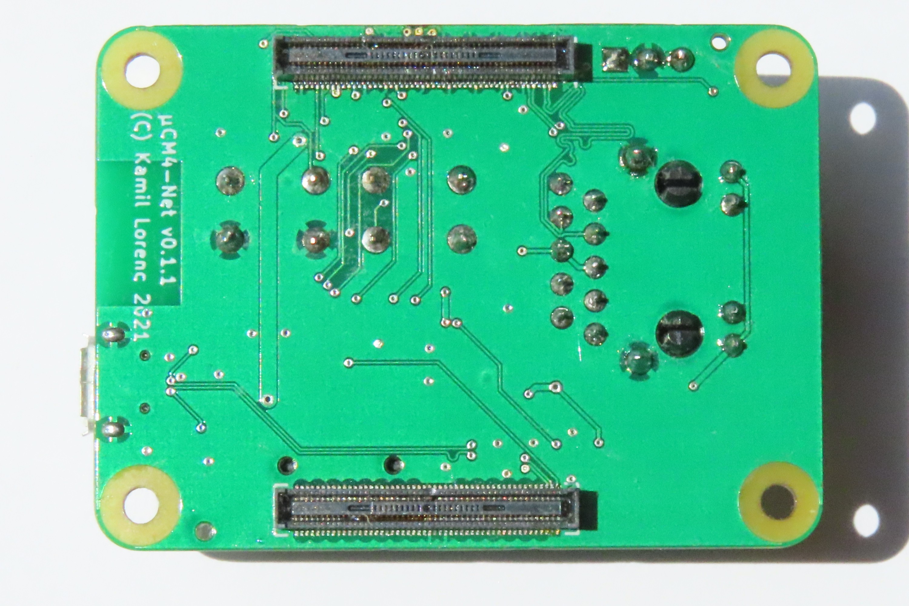
As can be seen it went well, so I went on. This is how finished board looks like:
![]()
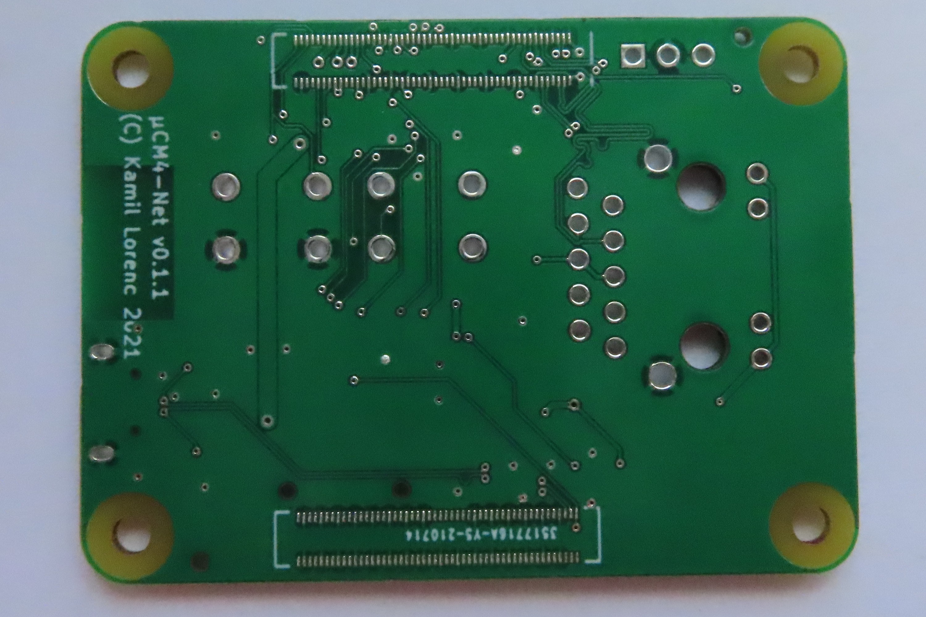
And bottom:
![]()
Generally, differences between this and previous board are almost unnoticeable and this is how it should be. It was meant to be, let's say, "bugfix" release. Existing problems indeed seems to be fixed now. In the final board however I encountered new issue - Ethernet does not want to negotiate 1 Gbps, what is unfortunate and regression since the first iteration. But I suspect it is build related, as the only modification around Ethernet connector and traces was diameter of shield mounting hole, which I believe did not cause this issue. Anyway I am going to investigate this and hopefully will be able to either fix it, or assemble another board to check if it persists.
For now I can sum up this iteration as (only small - due to Ethernet) success. Next goal is to set up some software in the direction of clustering and eliminating Micro SD card. I am also considering doing some modifications on the board, especially location of LEDs, as these are not exactly convenient for mounting in something like racks, what might be a problem for some people. And of course there is still supply chain problem for which I do not have any workaround, at least for now. I will keep posting updates in case of any news in the project.
-
New boards arrived
07/29/2021 at 12:16 • 0 commentsToday just a quick update. Last time I wrote that I ordered new boards. Today I received the package. After quick check, everything looks fine. One unknown was Ethernet connector, where one mounting hole was to small for easy assembly. It this revision it is way better and for me the risk of damaging the connector during assembly is eliminated.
Here is the board that I got:
![]()
And back of it:
![]()
As you can see it is already in version 0.1.1. I did not order assembly of U1-U3 ICs to save some money. If you want to reproduce the design, it should be enough to upload files available on Github (as assets to this release) and order (by default JLCPCB should offer to assemble U1-U3, if available).
Now the plan is to have it assembled, up and running till end of next weekend. Expect another update soon!
-
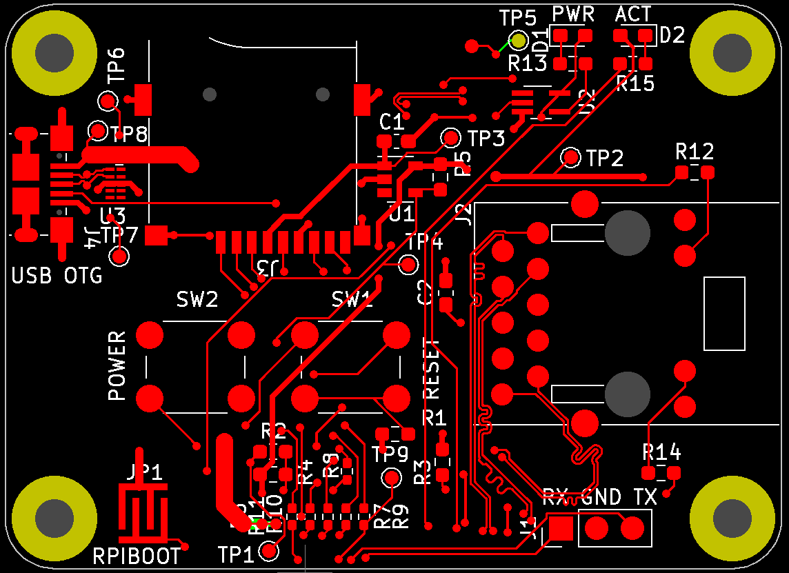
Fixed board revision sent to fabrication
07/13/2021 at 16:03 • 0 commentsIncreasing interest in my project motivated me to finally make next revision of PCB. Let me show you version 0.1.1. This is solely bugfix version and gets rid of most of the mistakes that I made on first iteration. There is nothing new, though. Goal here is to end up with a board that I can safely solder myself and use for further testing, possibly making 2 additional boards and trying some experiments in setting up Kubernetes.
Anyway, I fixed power rail width error, increased diameter of Ethernet shield hole, so now it should be way easier to place and this time I didn't forgot to regenerate drill files :) so now testpoints for USB should be on its place, too. Log of important changes is now on Github release page and obviously full log of changes is in Git's commit history. Here is the visualization of these few changes. First are drills (green is new, red is old):
![]()
And here is the complete board with new traces also in green (you don't see removals here):
![]()
As can be seen, changes are very subtle, but on the other hand, necessary.
Now, I have to wait few weeks before my order is produced and delivered. Then it will for sure take few more days to solder it properly. I hope this time will be better, as last time I didn't have enough soldering experience to do it right on first attempt, what finally took me couple of evenings to complete. In the meantime, maybe I will try to do some software development, as my plan was to boot CM4 with PXE, or something similar, so I will not need Micro SD card anymore. And this would be good improvement in the direction of setting up everything automatically for Kubernetes.
I also developed BOM and CPL files for SMT assembly a bit further, so in theory it is now possible to order assembly of all 3 ICs present on board - means ESD protection of USB, PMIC for SD card and LED buffer. I even attempted to do so for connectors, too, but with that I failed for now, so this is an exercise for the future due to wrong middle point on my custom footprints. During playing with that I noticed that RT9742CGJ5F (mentioned PMIC) is at no stock whatsoever. Even more disturbing is the fact that there is only one shop I could find, where they claimed to have some and with other Richtek-made PMICs it is not much better, or acutally all of them are at zero stock on LCSC. Fortunately, I still have 9 of the right ones, so for myself it is not a problem, but I can imagine someone trying to reproduce my design and failing to do so due to that. Also this would make any attempt of mass production impossible for the moment, unless redesigned to use different part. It is not a surprise for me, as IC shortage was first heard in context of nothing else, but PMICs.
PS. If you know any PMIC that can be used instead of the one mentioned and which I can easily source on LCSC, or any other non-Aliexpress-or-Taobao place, let me know. I can consider using it instead of the now unobtanium Richtek.
-
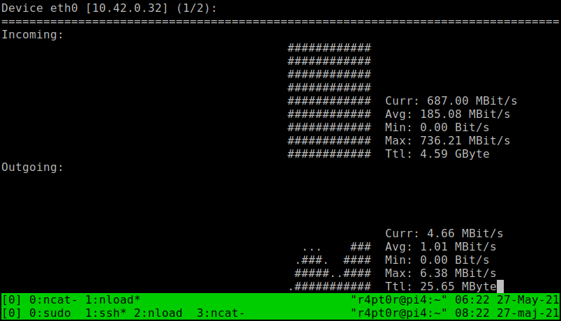
More Ethernet testing
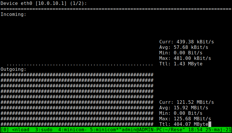
05/27/2021 at 06:36 • 0 commentsToday, finally I was able to set up stable Gigabit Ethernet connection to my laptop. Did some quick test by sending random file from my laptop's SSD to CM4 and storing in /dev/null. Here is the result measured by nload:
![]()
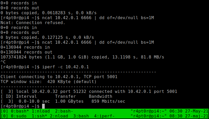
And I got quite nice ~700 Mbps. I still hope this is not maximum for CM4, but SSD was bottleneck this time. Let's see what iperf is gonna say. And it showed this:
![]()
By the way you can see dd counting previous attempt. So, here we have ~860 Mbps. This I can believe in.
Then the summary is that my board does its job nicely. I played quite a lot with trace length matching tool in KiCAD to make sure that all traces carrying Ethernet signals are of exactly same length. I'm curious what would be the result if I ignored that. But I think that spending money and time on next batch of test boards is not worth it :)
-
Test of Ethernet connection
05/25/2021 at 15:54 • 0 commentsuCM4 carrier board was designed with network projects in mind, so the most important thing to check is how fast the internet connection could go.
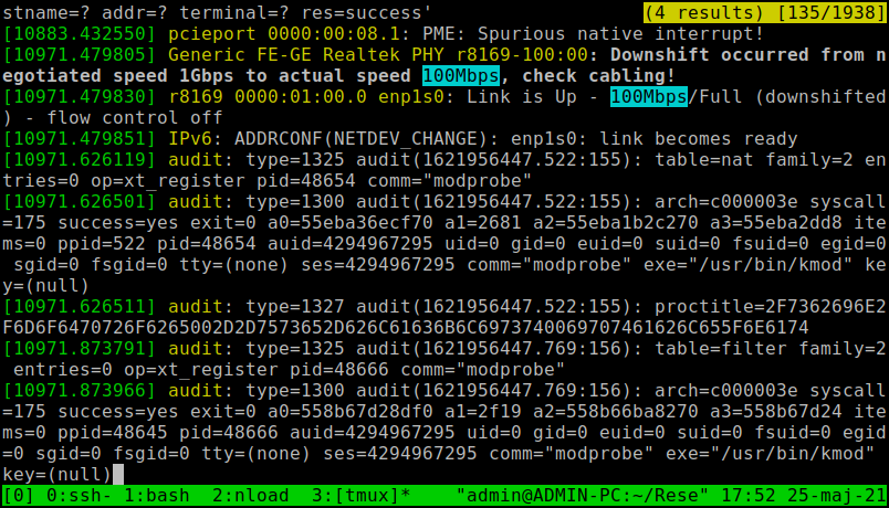
Today I did some quick tests on that matter. First test went rather unsuccessful, as definitely my laptop, that is sharing internet to CM4, opened connection at 100Mbps. I tried with few cables that claim to be Cat5e, but all of them worked as bad as first one.
My PC suggesting that cable is the issue and synching at 100 Mbps:
![]()
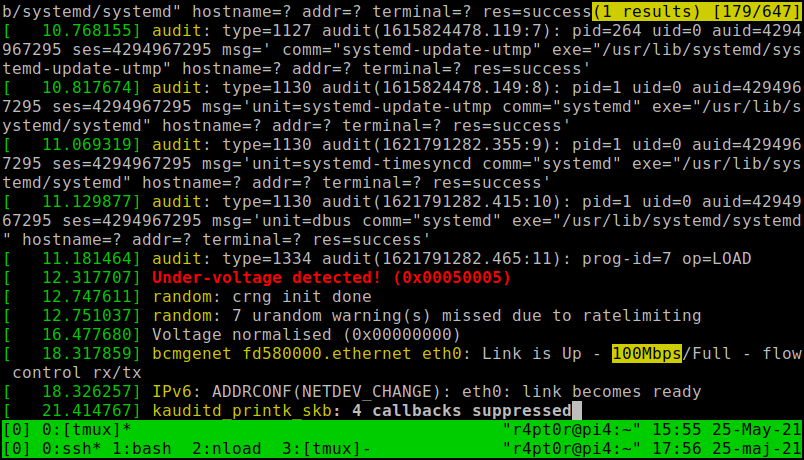
CM4 only tells me that I got 100 Mbps:
![]()
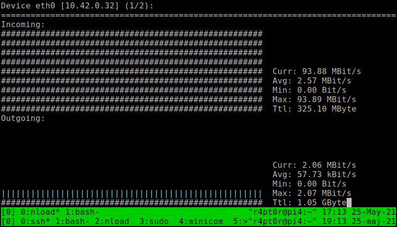
Despite being unlucky with port speed, I tested nload to see how much do I get on 100 Mbps link. It showed ~90 Mbps. Nice.
![]()
After trying 3 cables I decided to change tactics. I reminded myself that I have old Wandboard PICO-PI-IMX7 lying around and collecting dust. Fortunately it stills has working OS flashed, so let's try that:
![]()
100 MBit/s crossed, so first small success.
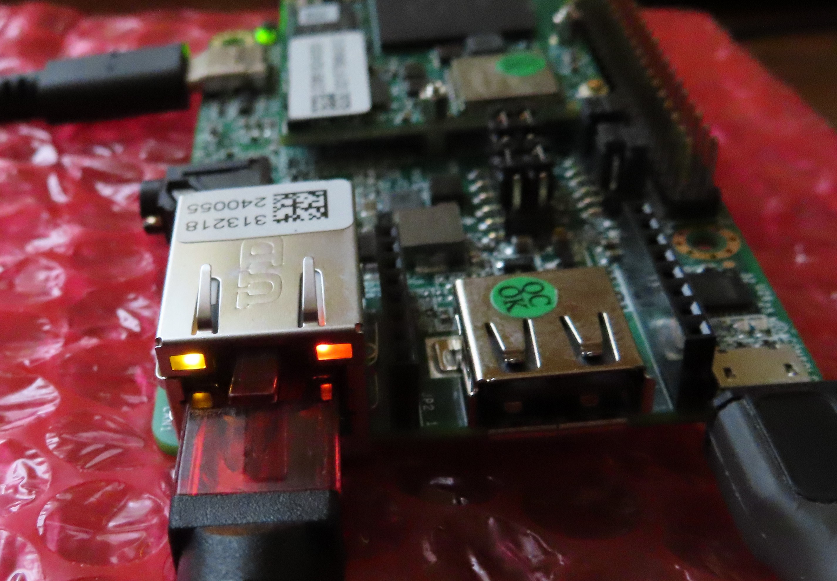
Wandboard clearly indicates 1 GbE link with its orange LED, instead of usual green, that I saw just a moment before with different cable:
![]()
I wonder why they didn't do same on Raspberry Pi. Even if I used same UDE connector on my board, there is no signal indicating 1 GbE, instead of 100 Mbps, AFAIK. Weird.
Next time, I will try to test connection from CM4 to Raspberry Pi 4, as I suspect Pico Pi is bottleneck here. At first I tested connection from Pico Pi to PC and got almost same ~120 MBit/s. i.MX7 is not the newest SoC, so it is not really a surprise, you can't get more from that. However, before testing Pi4, I have to prepare another OS, as till now I used card borrowed from my Pi4, so can't do that quickly, unfortunately.
uCM4
Compute Module 4 carrier board for network projects that is as small as CM4 itself
 For today this is all I have. I hope in the coming days I will be able to play with the boards a bit more.
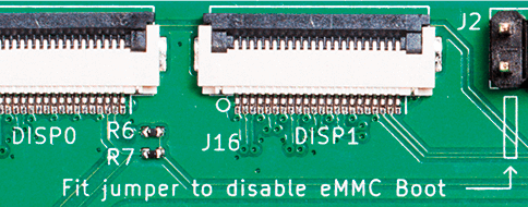 So, if you are lucky to have CM4IO, you just put a jumper to first position of J2 connector, connect to power and should be ready for flashing.