-
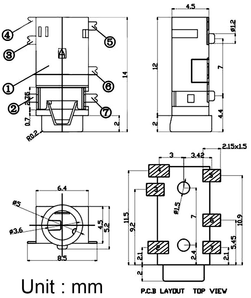
1Buy a 3.5mm Jack connector with a suitable size.
The available room is about 8-9mm in height, so the one I picked was 8.5mm and I bent the pins to fit it without problems.
This was the item:
https://www.ebay.com/itm/382841364175
![]()
You should look for SMD parts, otherwise size will be too big.
Your mileage may vary depending on what you buy.
-
2Disassemble device
See my other project for this:
-
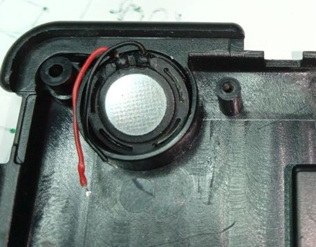
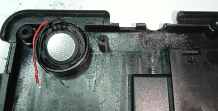
3Desolder the speaker from the PCB
Desolder the speaker from the PCB:
![]()
If you have a multi-meter, check the resistance, should be 8 ohms if your speaker is like mine.
The wires and the connection point are very fragile, don't abuse them or they will probably break.
-
4Grind and cut the required plastic parts.
The goal is to have a final mount position that should be more or less like this one:
![]()
Take your measures and cut a slot next to the tv out.
You must also cut some plastic from the round bar to allow the connector housing of your headphones to fit.
![]()
Grind the plastic near the output to allow the connector to rest flat.
![]()
-
5Bend the connector pins if needed.
If you mount it as suggested, this will be necessary.
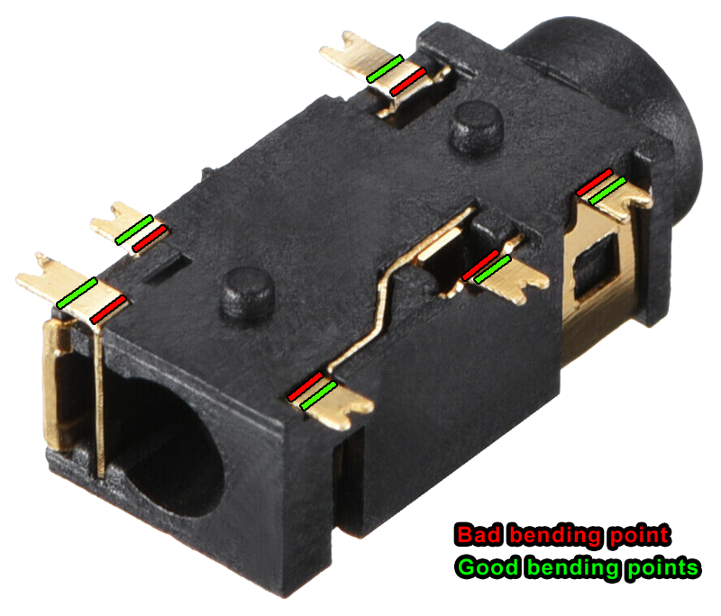
Bend the pins upwards to shorten the connector total width.
Be very careful, the bending points should not be the ones shown in red, it's easier to bend it by those points, but because the metal is very fragile, and this is the point that has already been bent in the factory, it will break or at least will make it much more prone to breaking through the rest of the process.
Using small pliers it's quite easy if you put the tip near the green point and apply the force correctly.
![]()
-
6Prepare the connector wiring.
Solder some wires as shown.
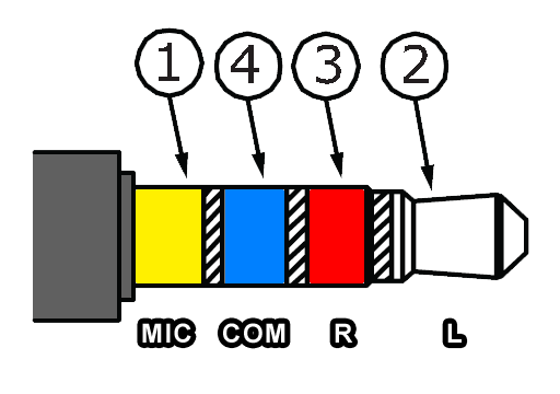
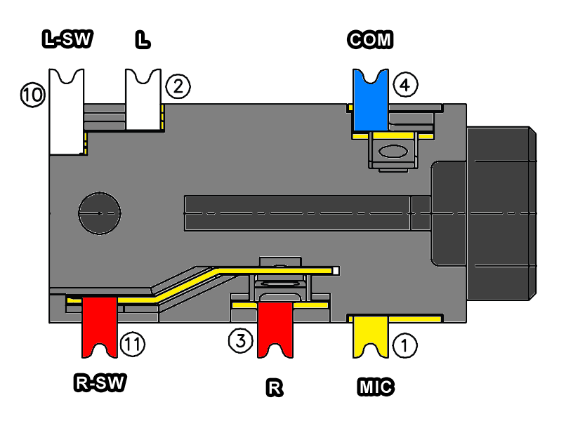
Because the speaker is mono, we can use both channels together, this wiring may be different in your connector, check the documentation if you have it, or use a multimeter to check the pins.
This are the jack signals.
![]()
This was my pinout (most connectors have the same):
![]()
These are the bridges I did:
![]()
So, I soldered together:
L & R
L-SW & R-SW (these are the switched outputs, when jack is inserted, contact is open between L & L-SW and the same with R & R-SW).
COM & MIC (these are the common and microphone, sometimes reversed in old head sets, bridging them together we make sure we have the common connected).
-
7Make sure everything still fits
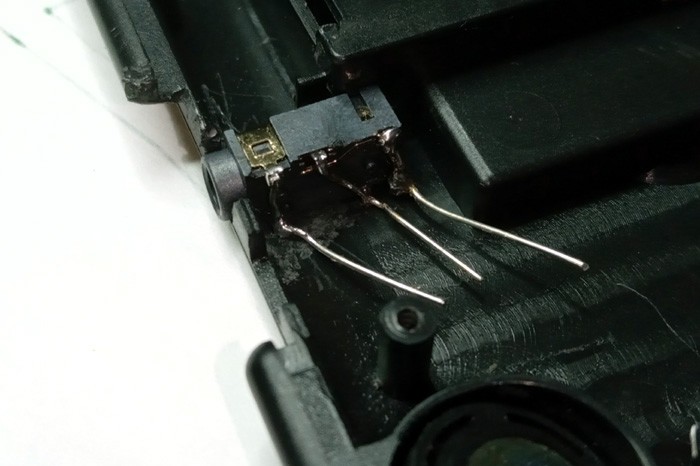
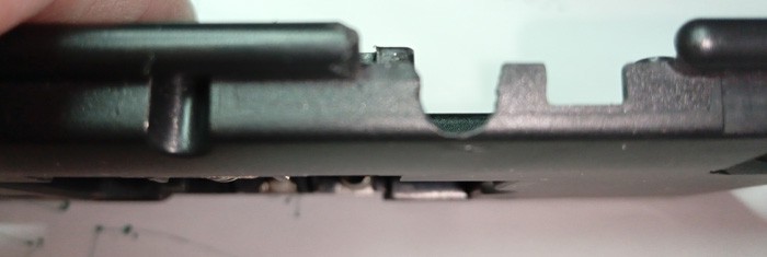
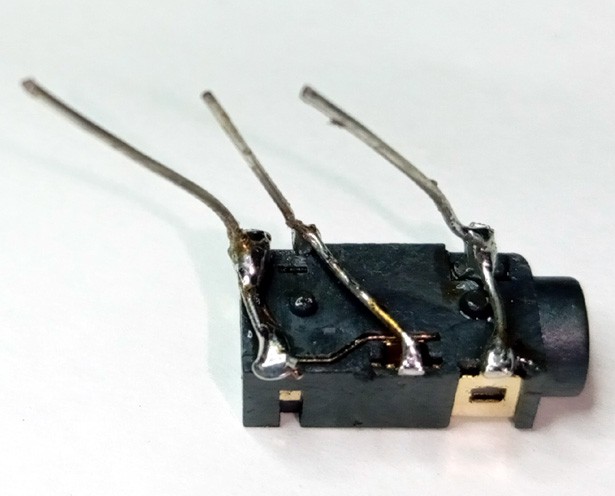
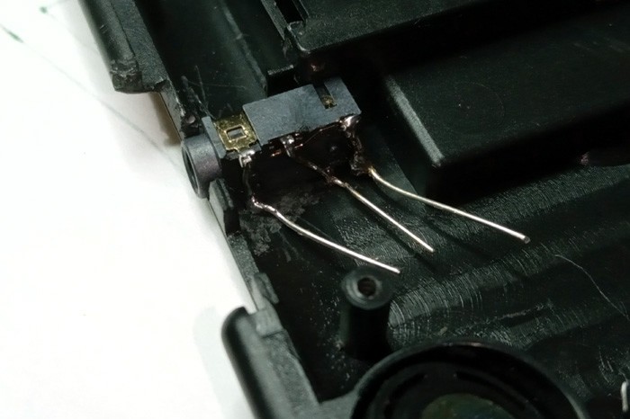
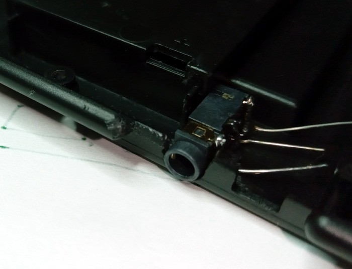
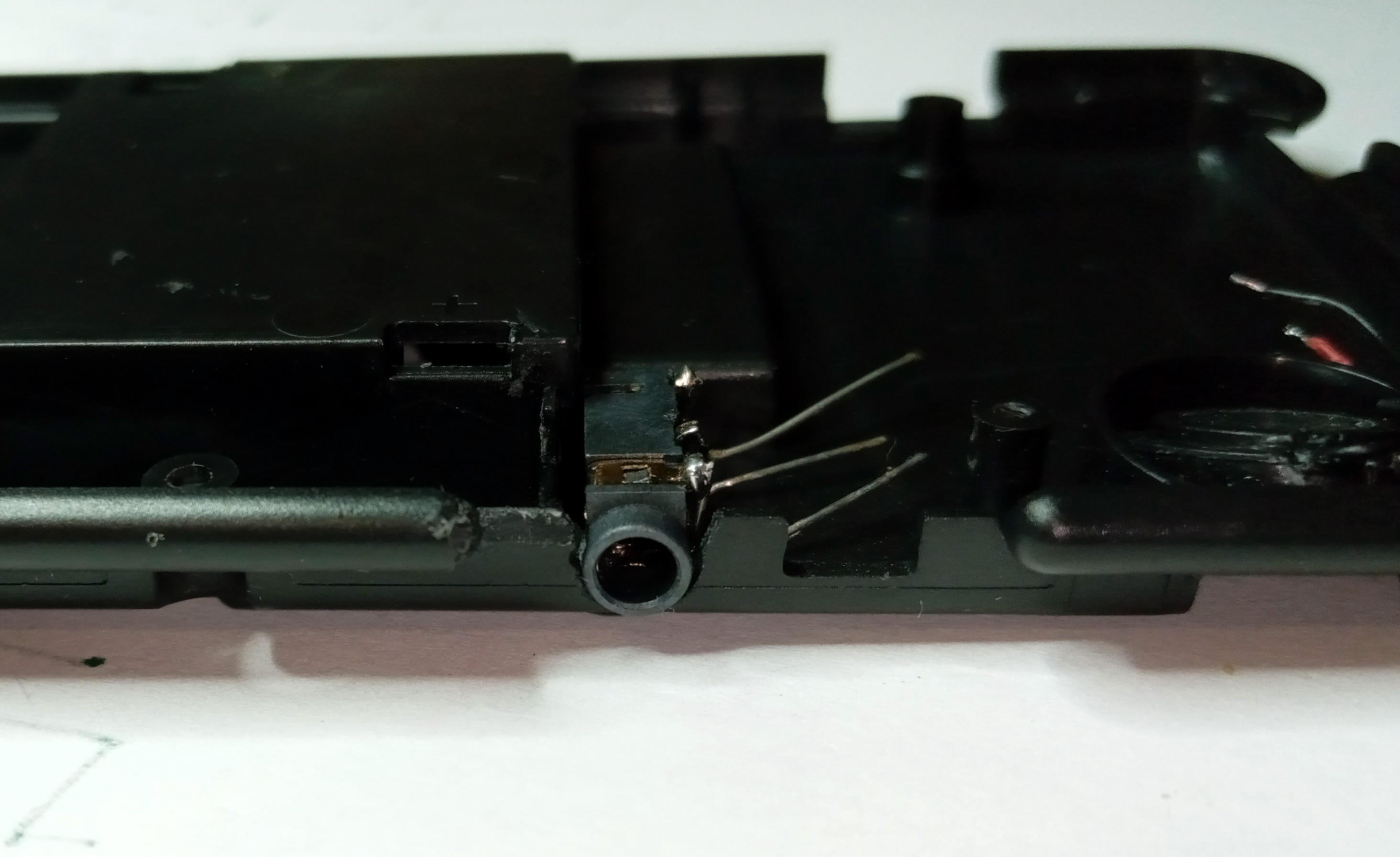
Make sure the connector fits after soldering the wires.
Try to put the PCB on top, there should be some room to move the connector, if after putting the PCB the connector can't be moved, it's too thick. Either you bent the pins the wrong way or you put too much solder.
![]()
![]()
![]()
-
8Do the rest of the wiring
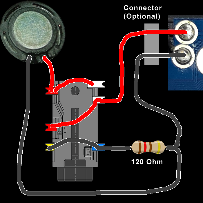
Use this diagram as a reference:
![]()
The speaker common (BLACK) is wired directly to the original speaker.
The speaker + wire (RED) goes through the connector switches.
The headphones speakers are driven in parallel and the signal is attenuated using the 120 ohm resistor (otherwise the sound will be too loud and you'll also hear background noise).
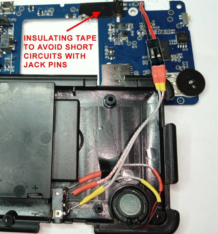
Should end up in something like this.
![]()
The resistor is inside the left yellow shrink tube.
Note: the wires are soldered to the bottom of the board, not the top as they were originally, this way, all the wiring remains bellow the board.
It's not strictly necessary, but my advice is to put a connector between the new wiring and the board, it will be useful for the next steps and future board mods.
If any doubts arise, this page may be helpful:
https://www.cuidevices.com/blog/understanding-audio-jack-switches-and-schematics
-
9Do a test, with the multimeter.
If done correctly:
When no headphone is connected:
Measuring between the board connection points, you should measure the same resistance of the speaker measured previously.
You should have continuity between the board red and speaker red and the same with the black.
When a headphone is connected:
Measuring between the board connection points, you should measure 120 + your headphone speakers in parallel, normally 16 ohms, for a total of 136 ohm approx. Also, if you put your headphones on, you should hear a small noise when you do this test.
You should not have continuity between the board red and speaker red, you should still have continuity with the black wires.
-
10Do a test before reassembling it all
I did it connecting only the board and putting the rubber buttons on top, not the screen.
After powering the machine and pressing the D-PAD L or R you should hear the menu sound.
Discussions
Become a Hackaday.io Member
Create an account to leave a comment. Already have an account? Log In.