Michael Perrone
-
December update
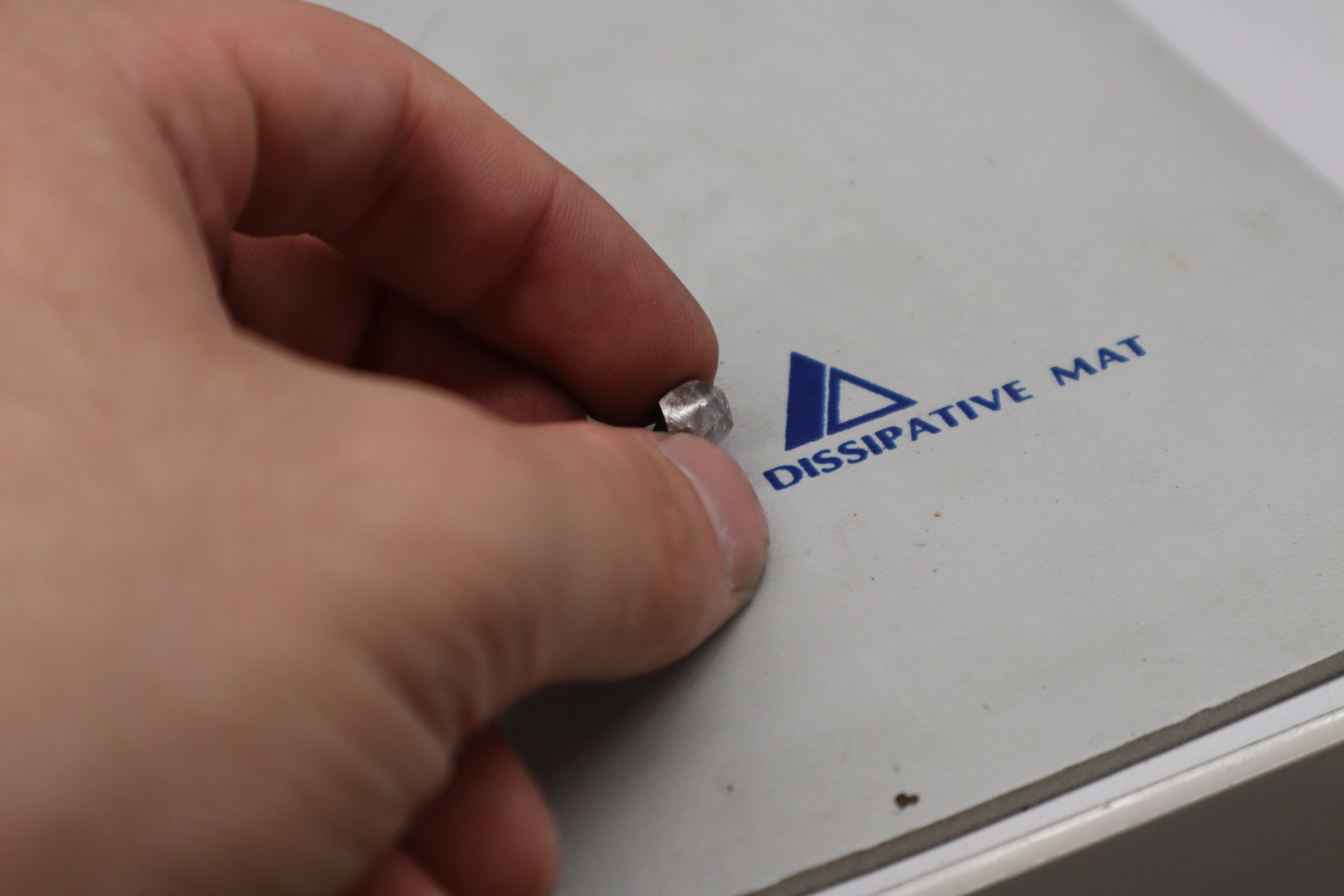
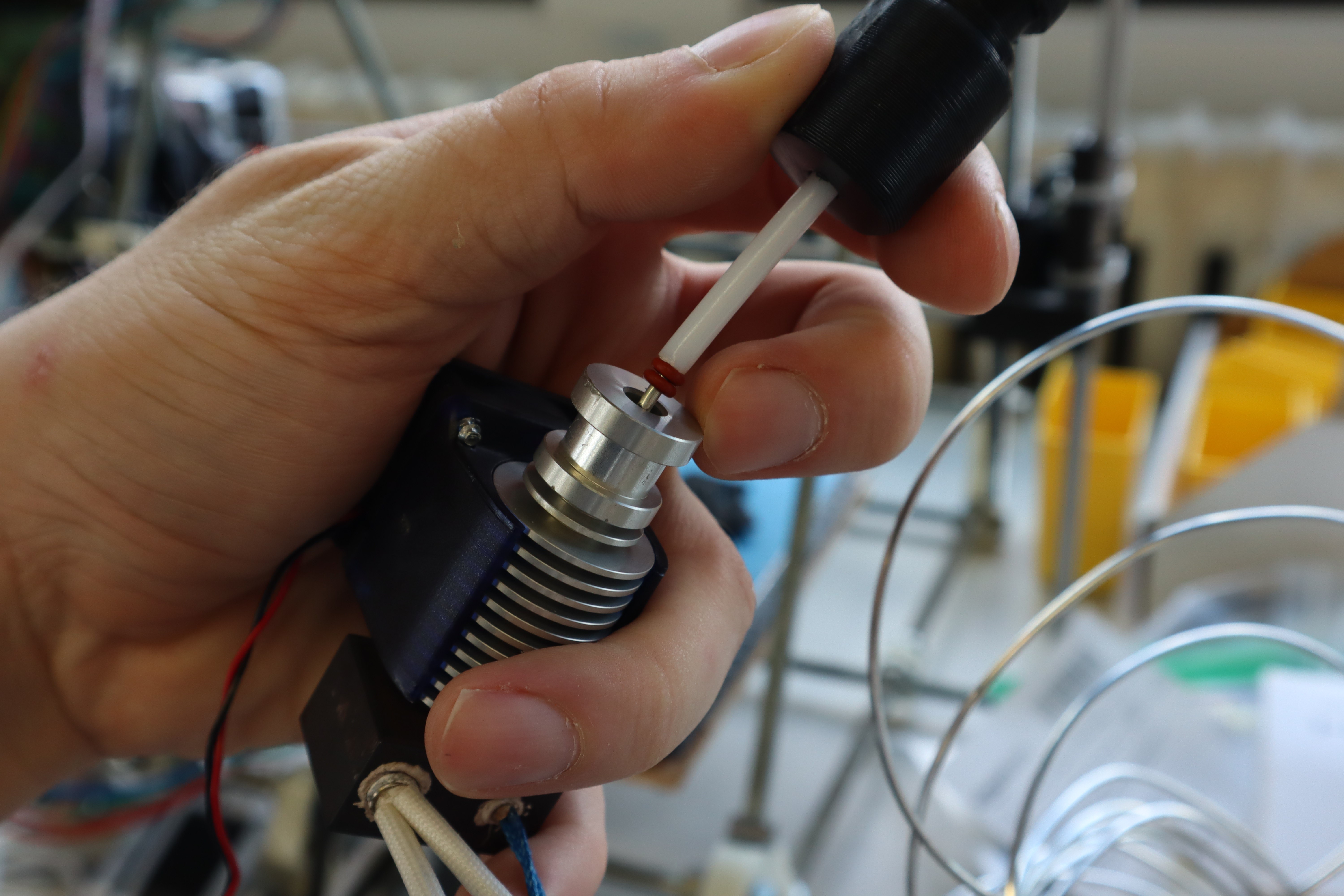
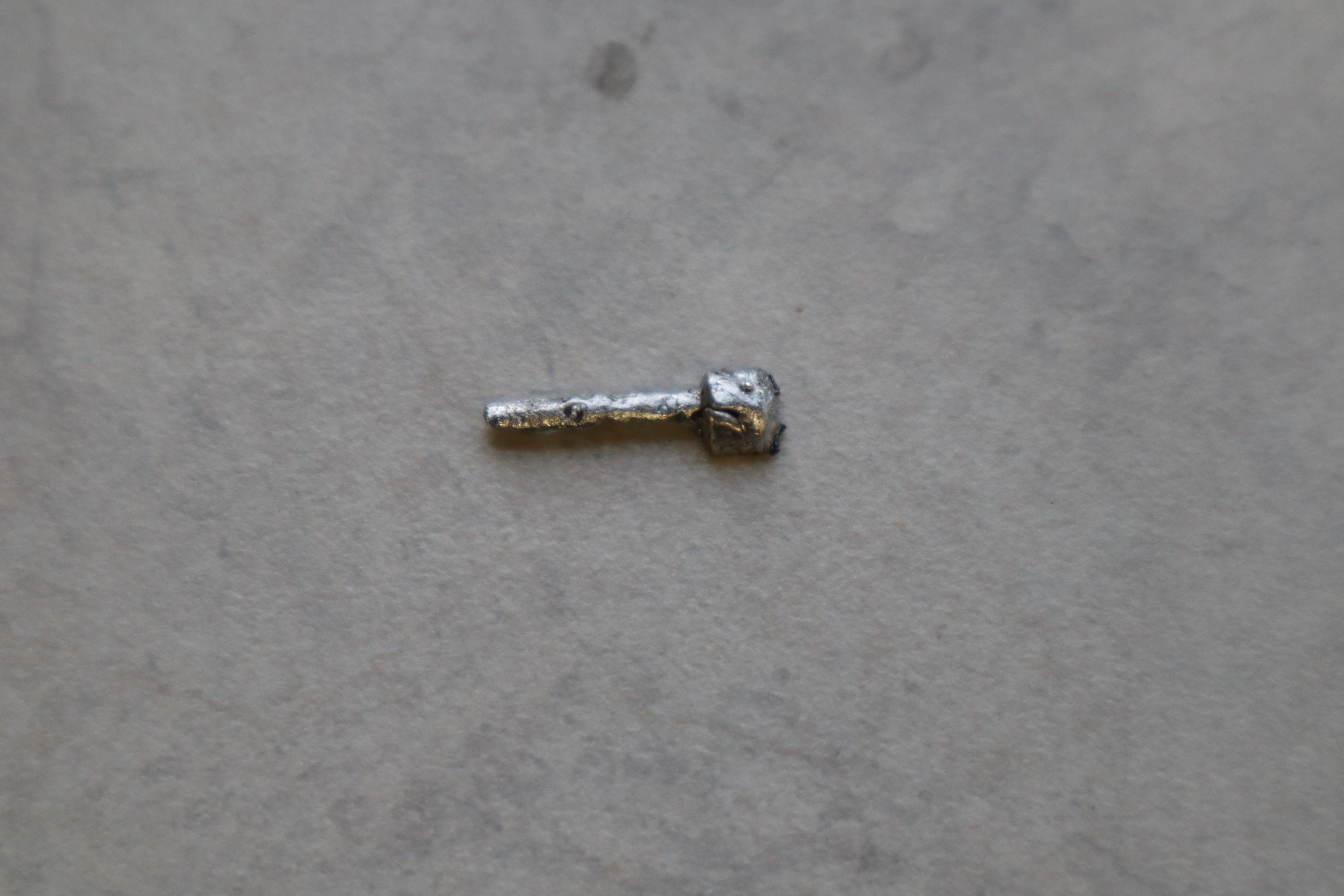
12/29/2021 at 20:29 • 0 commentsIt’s time for the next project update! The past few updates, I encountered various clogging issues, which was more or less to be expected with this technology. First, nozzle clogging was due to X-Pando pipe sealant that had gotten into the liquid metal, which was easily remedied by applying the X-Pando to the male pipe threads instead of the female ones. Then, clogging occurred in the heatbreak, where liquid metal soldered to the stainless steel wall of the heatbreak and froze, locking the wire in place. I know this because I accidentally broke a heatbreak
![]()
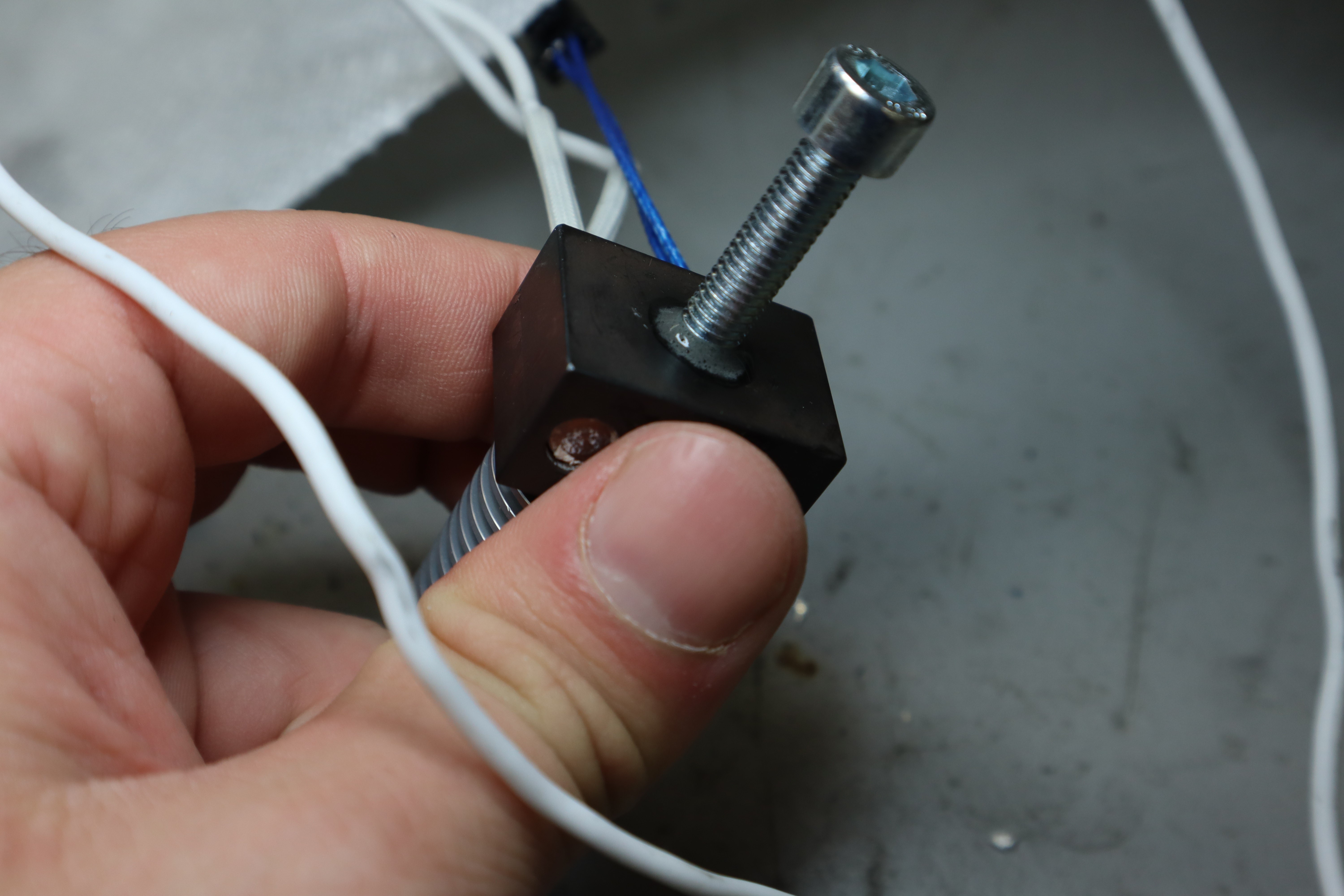
and figured I’d get some pictures of the jammed surface and see how hard it was to remove.
![]()
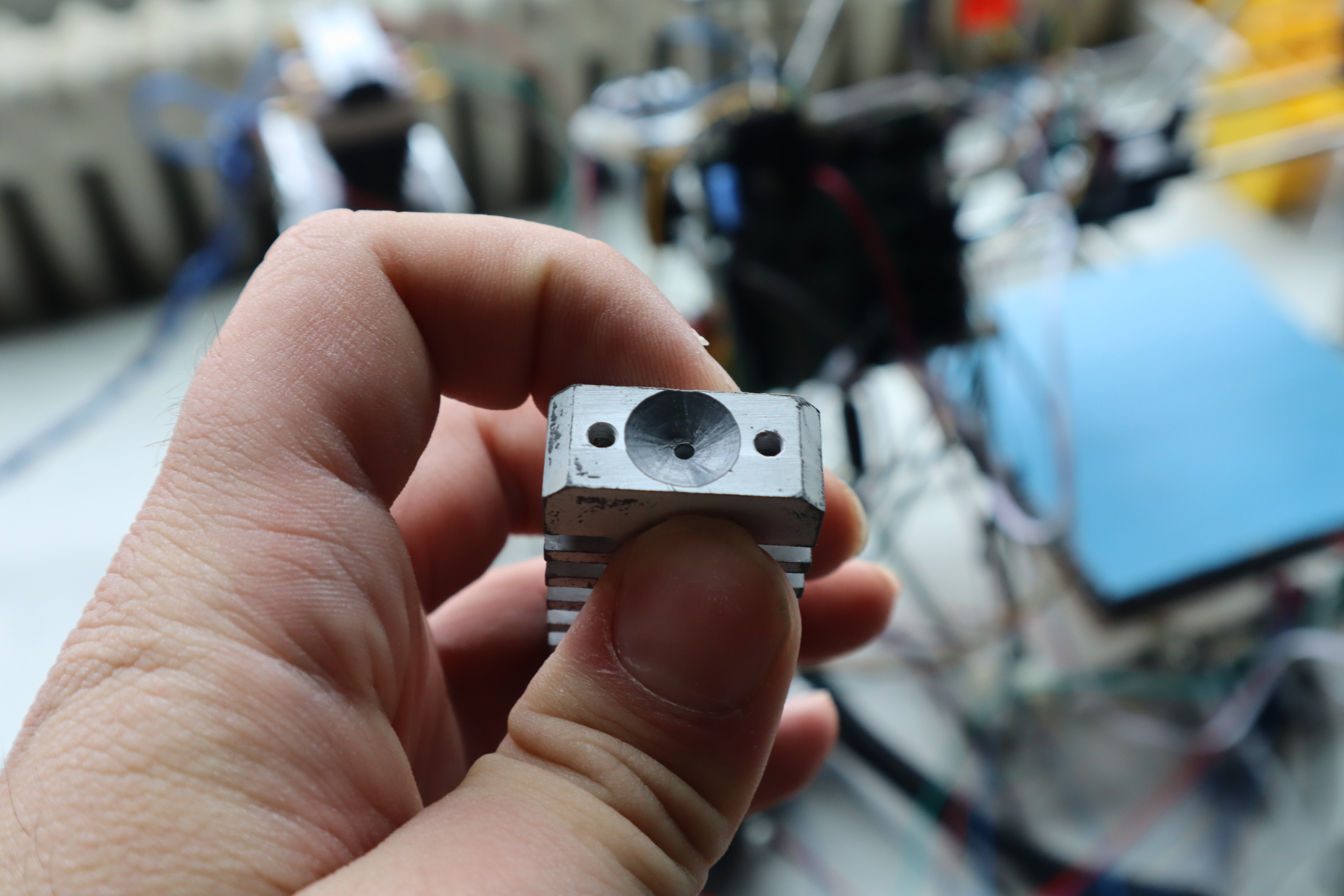
It was clearly soldered to the surface in the heatbreak. This was mostly solved by using a titanium heatbreak instead of a stainles steel one. Finally now, I’ve encountered the granular jamming common to semisolid alloys, which my semisolid metal printing technology is developed to get around.
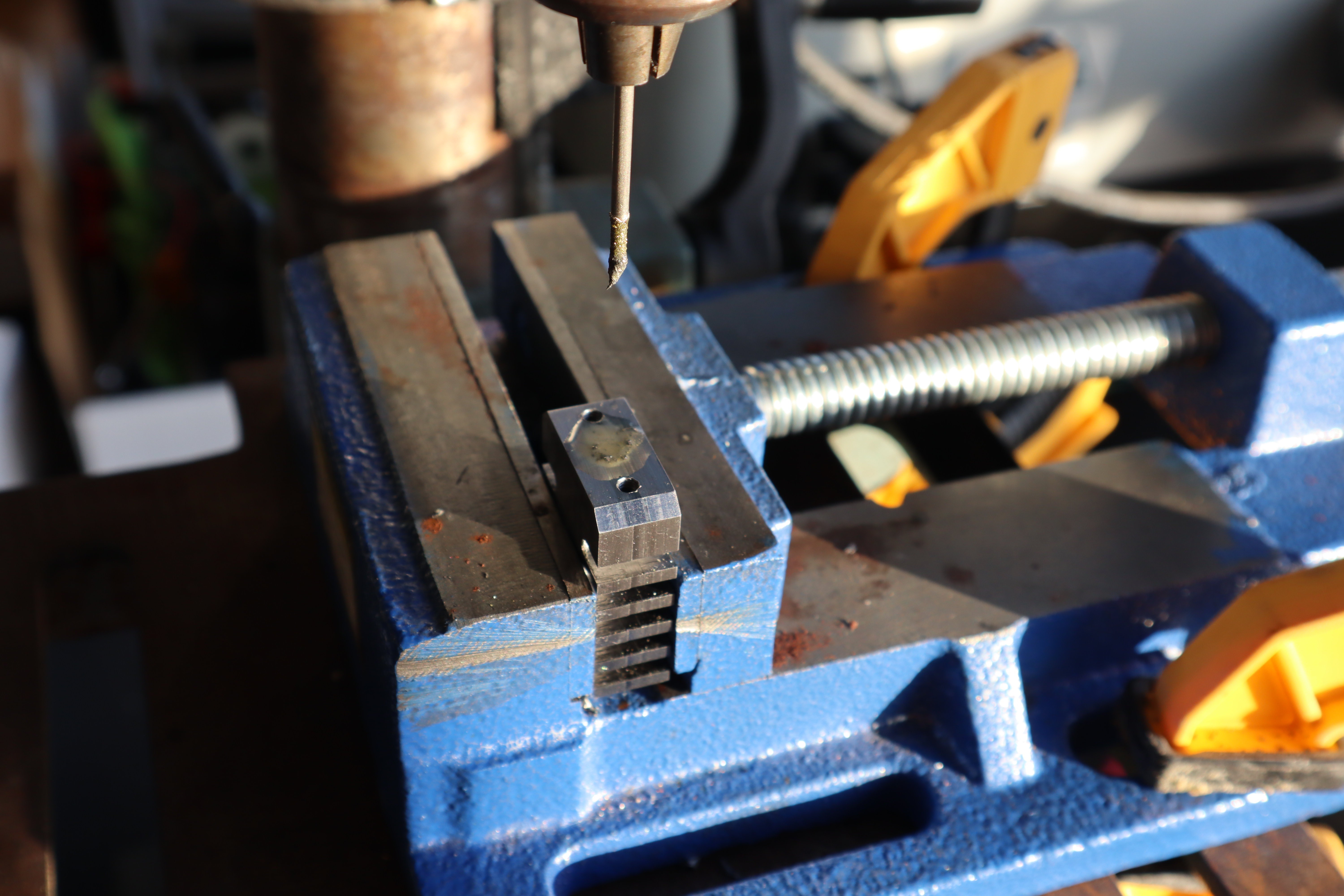
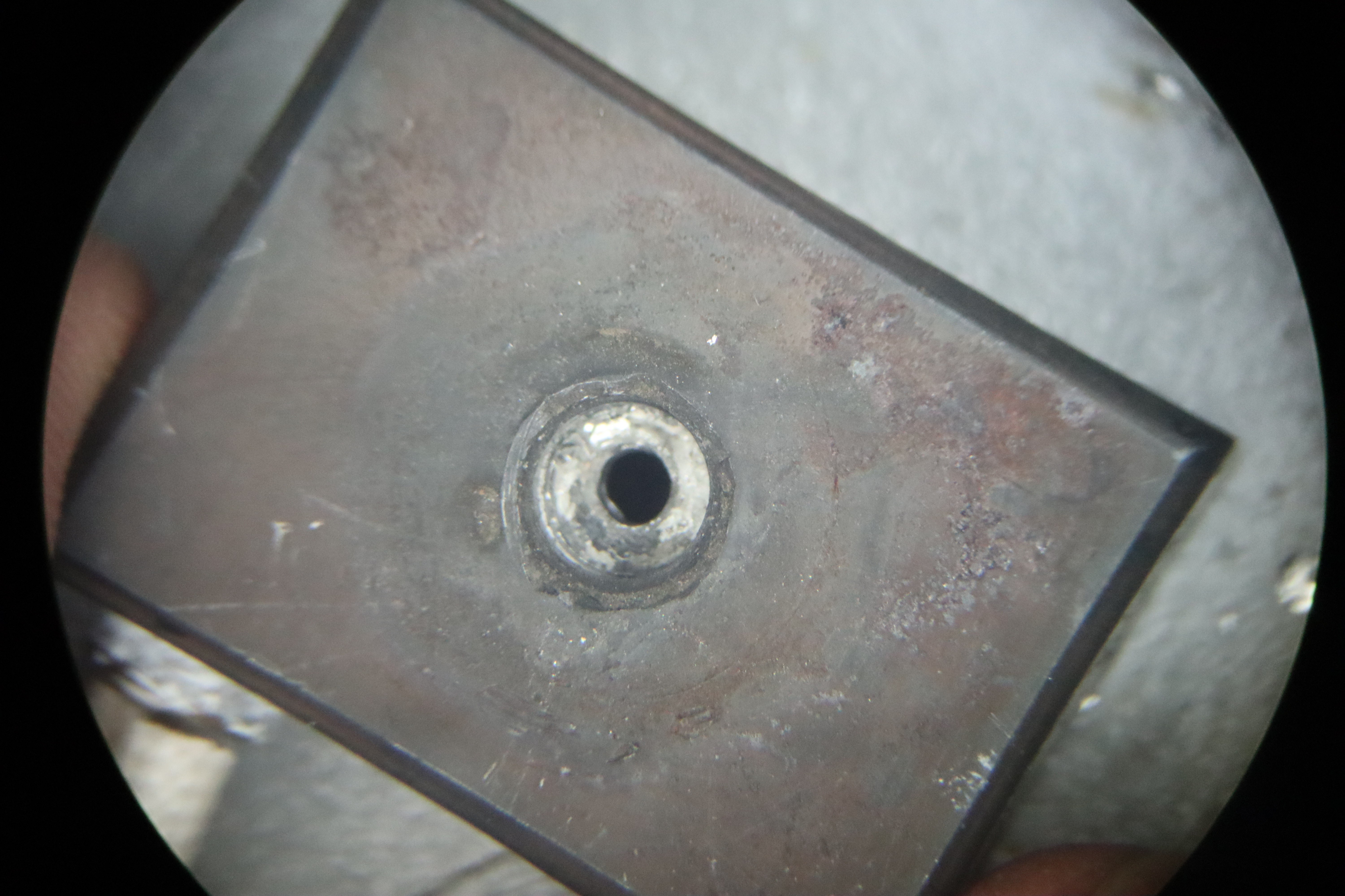
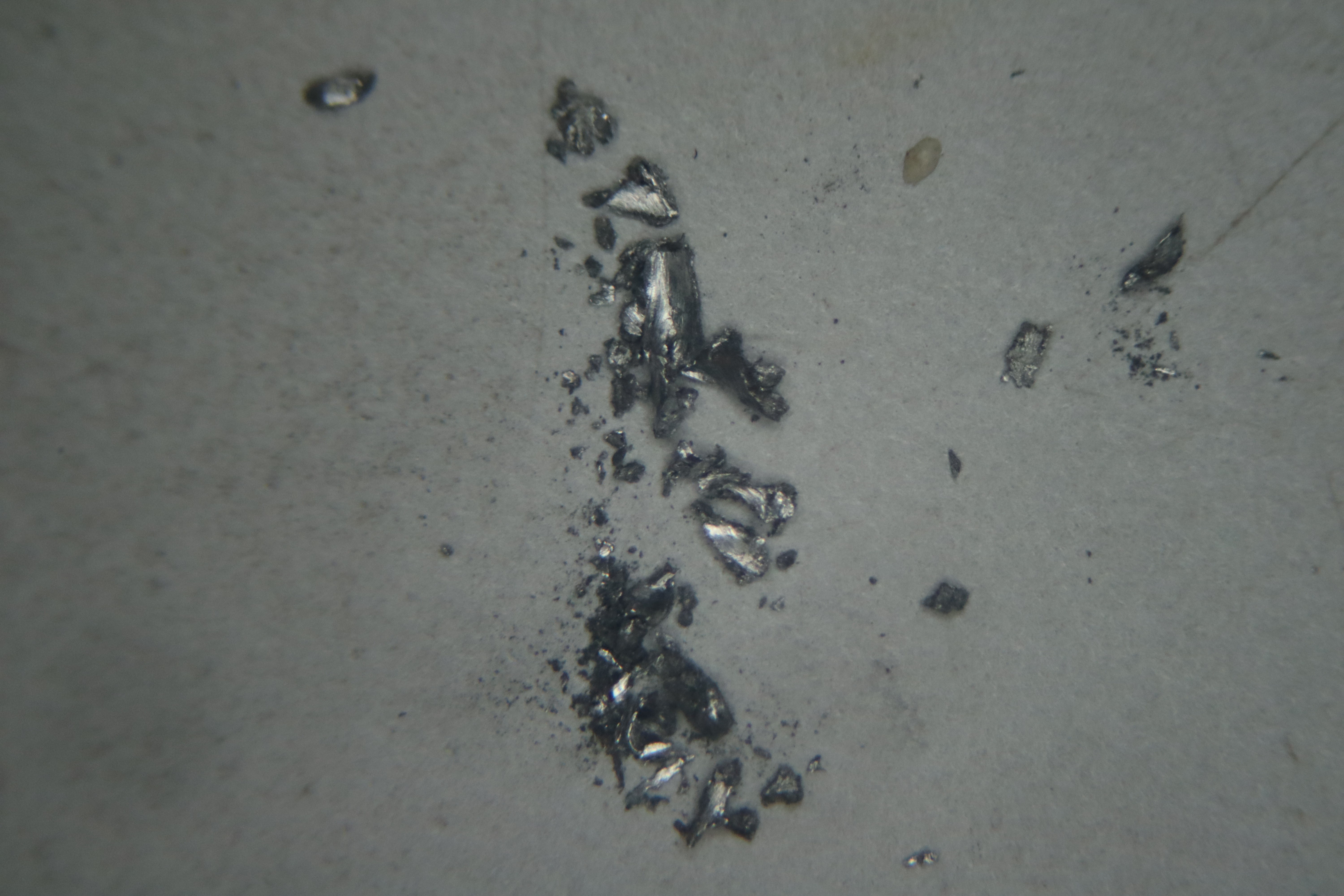
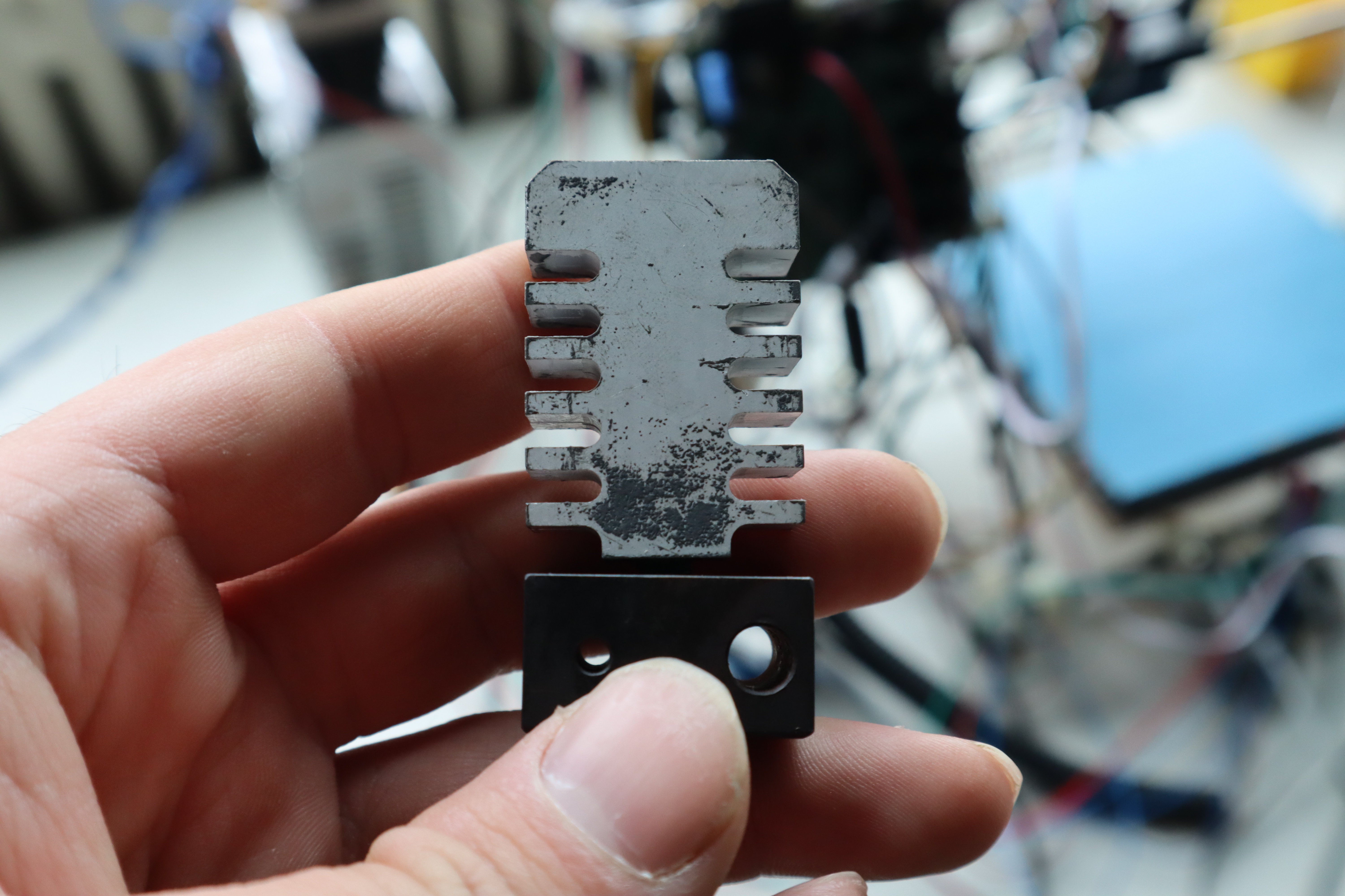
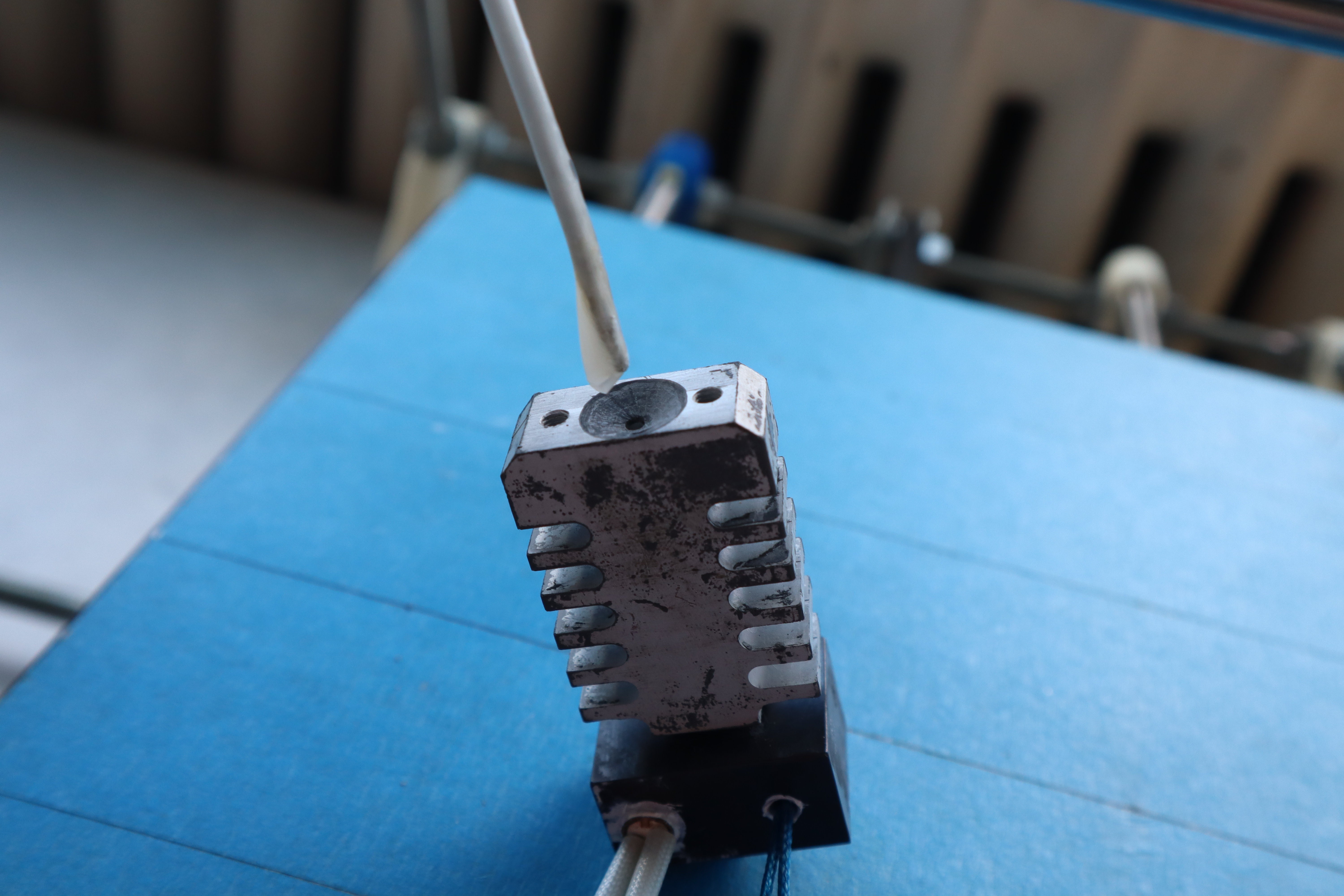
Granular jamming in semisolid metal alloys is easy to identify: when jammed, the solid phase can separate from the liquid phase, forming two different masses of metal with different phase equilibria, compositions and therefore melting points. When inspecting the nozzle, I found that the material in it was indeed solid metal, but it barely melted even with a soldering iron around 410C, the melting point of zinc metal. This means the majority of the tin had been pushed out due to granular jamming, increasing the melting point of the remaining material and eventually clogging the nozzle. I was surprised to find that this mass of zinc-concentrated material filled the entire nozzle all the way to where it meets the heatbreak: evidently it took a few layers of printing before the granular jamming got that severe. The deposited alloy also notably had a narrower semisolid range than expected, flowing readily and not keeping in place as it should. That metric is less conclusive, but seeing both things happen together is proof positive of this failure mode.
![]()
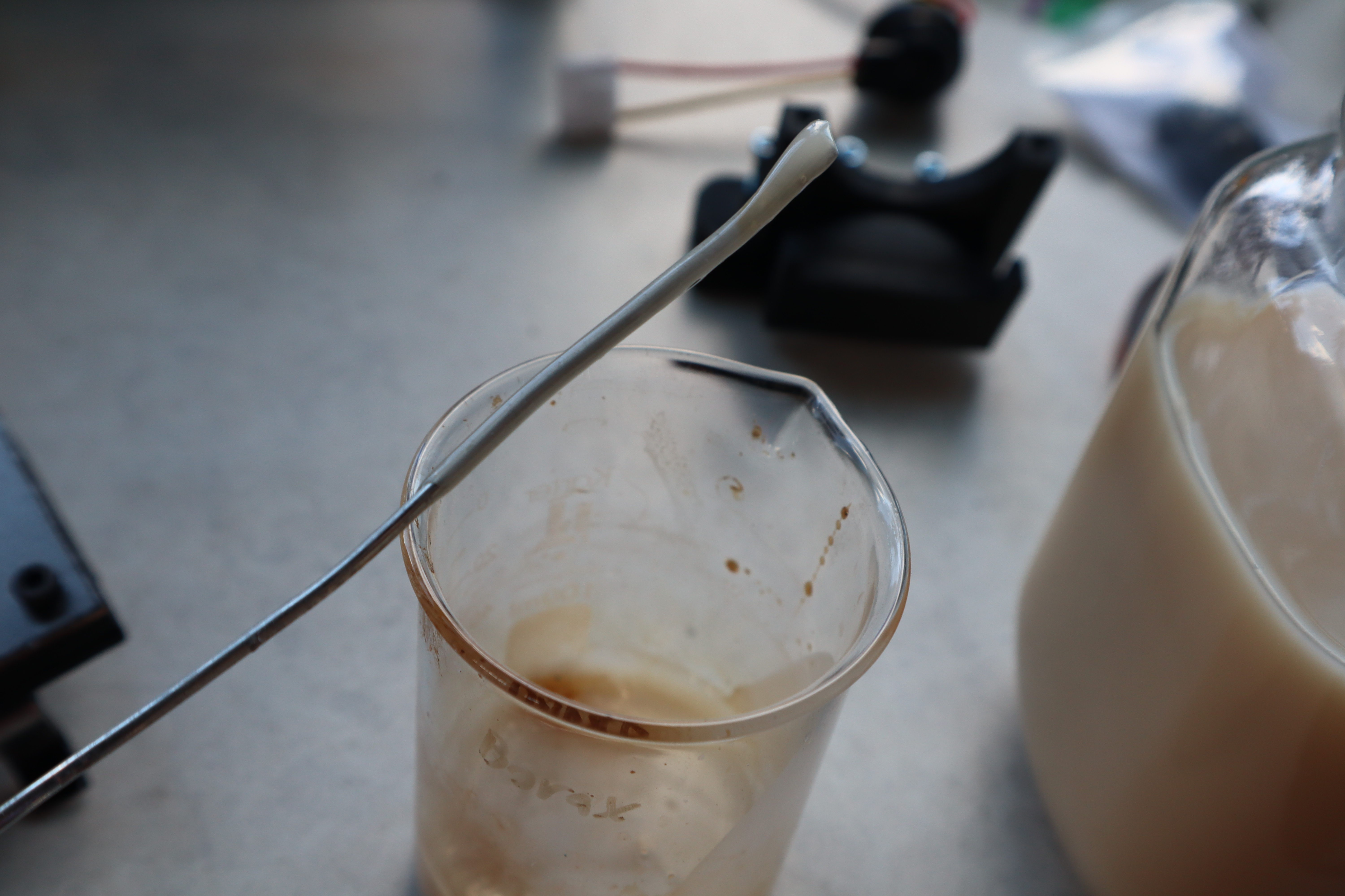
And just to make extra sure, I drilled the tin-zinc out and found only solid metal, confirming that it couldn't be any other form of jamming.
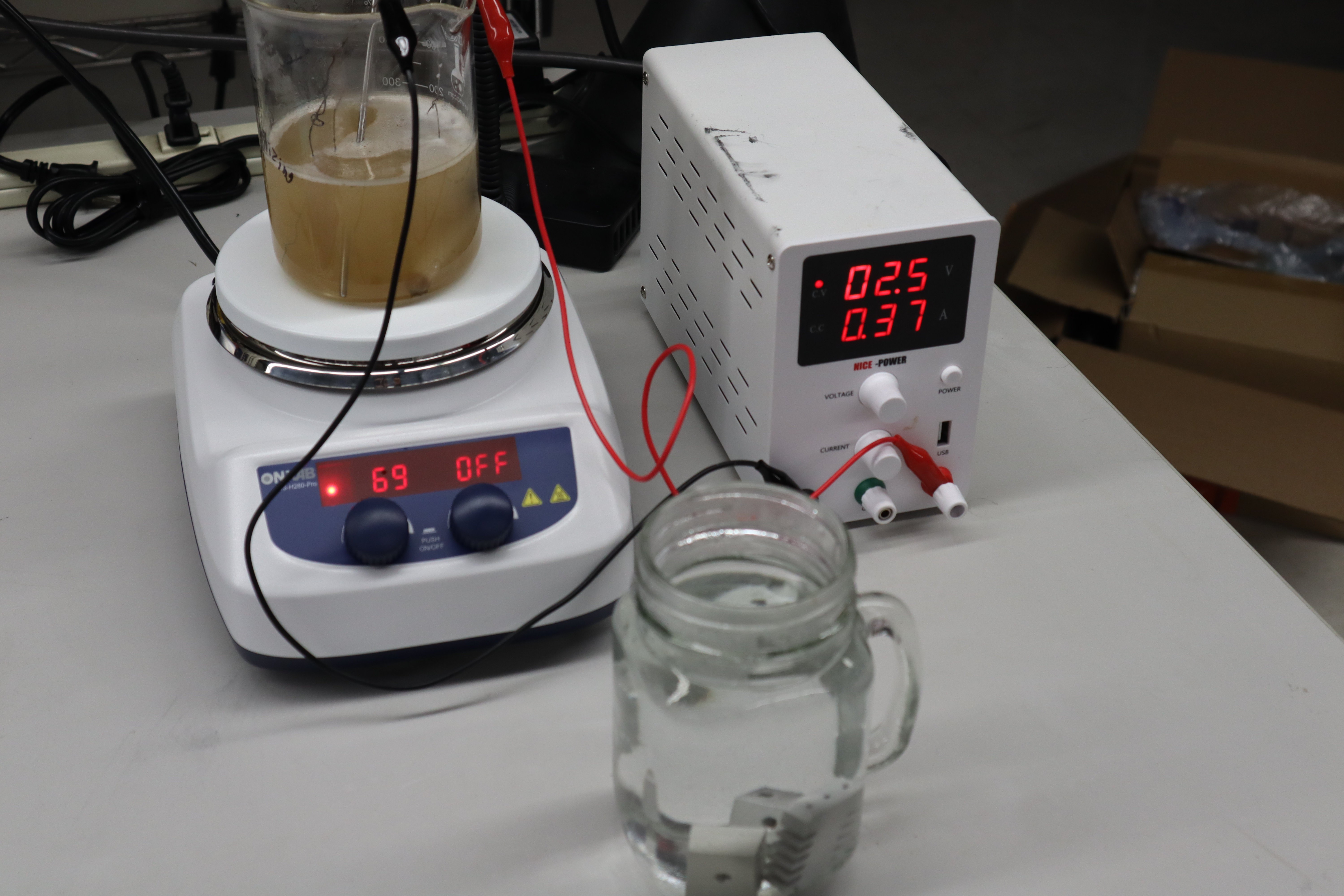
So what happened? I hypothesized that the temperature measured by the thermistor was not accurate to the temperature at the actual nozzle tip. To test this I got my multimeter with a standard type K thermocouple and wetted it with glycerol-ZnCl deep eutectic solvent for the best possible thermal contact, and touched it to the nozzle tip when the printer was up at various temperatures. I found that at 300 C by the thermistor’s measurement, the nozzle tip was actually at 266 C, and at 325 C the tip was at 286C. On their own these would be fine, since the tin-zinc alloy I use is fully molten around 250C. But the print bed is only at 180C or so, so once the nozzle touched the print bed, even at these temperatures, the nozzle tip would have fallen to 223 or 243. No lower printing temperatures would have worked either, and the previous printing attempts were done with a nozzle temperature around 280C according to the thermistor, so it’s possible some of the clogging in the previous runs was also due to granular jamming, though they definitely jammed first due to other mechanisms, because the metal in the nozzle in those runs was easier to melt out of the nozzle once disassembled - well below the melting point of zinc.
According to these measurements, the temperature actually required to extrude properly with this alloy is above what E3D’s standard thermistors can reasonably handle. Indeed, even to reach 325C, I had to extend the range on the thermistor lookup table, measuring with the thermocouple to make sure my additions to the table were accurate enough. It didn’t work particularly well, but it was enough to test with. Now I’ve purchased a PT100 RTD and a T-D500 thermistor, which both claim to go up to 500C. Those should do the trick; we’ll see when they arrive. There’s a slight possibility that printing at such high temperatures will cause the feedstock alloy to be too fluid or not have a yield stress at the moment of deposition, but hopefully as for Wire Arc Additive Manufacturing, this can be controlled adequately with the right system settings. Just in case though, I’ve got all the materials I’ll need to add a brush/wick to the nozzle to help direct the flow of the semisolid alloy, which should work just like a paintbrush. I also got a wider nozzle in case that helps prevent granular jamming, but hopefully I won’t need to use that. I suppose I could use a lower melting point alloy instead of increasing the process temperature as well, which would aid in printing this material alongside plastics, but that would take more time to make and at this point I’d just like to see the machine work.
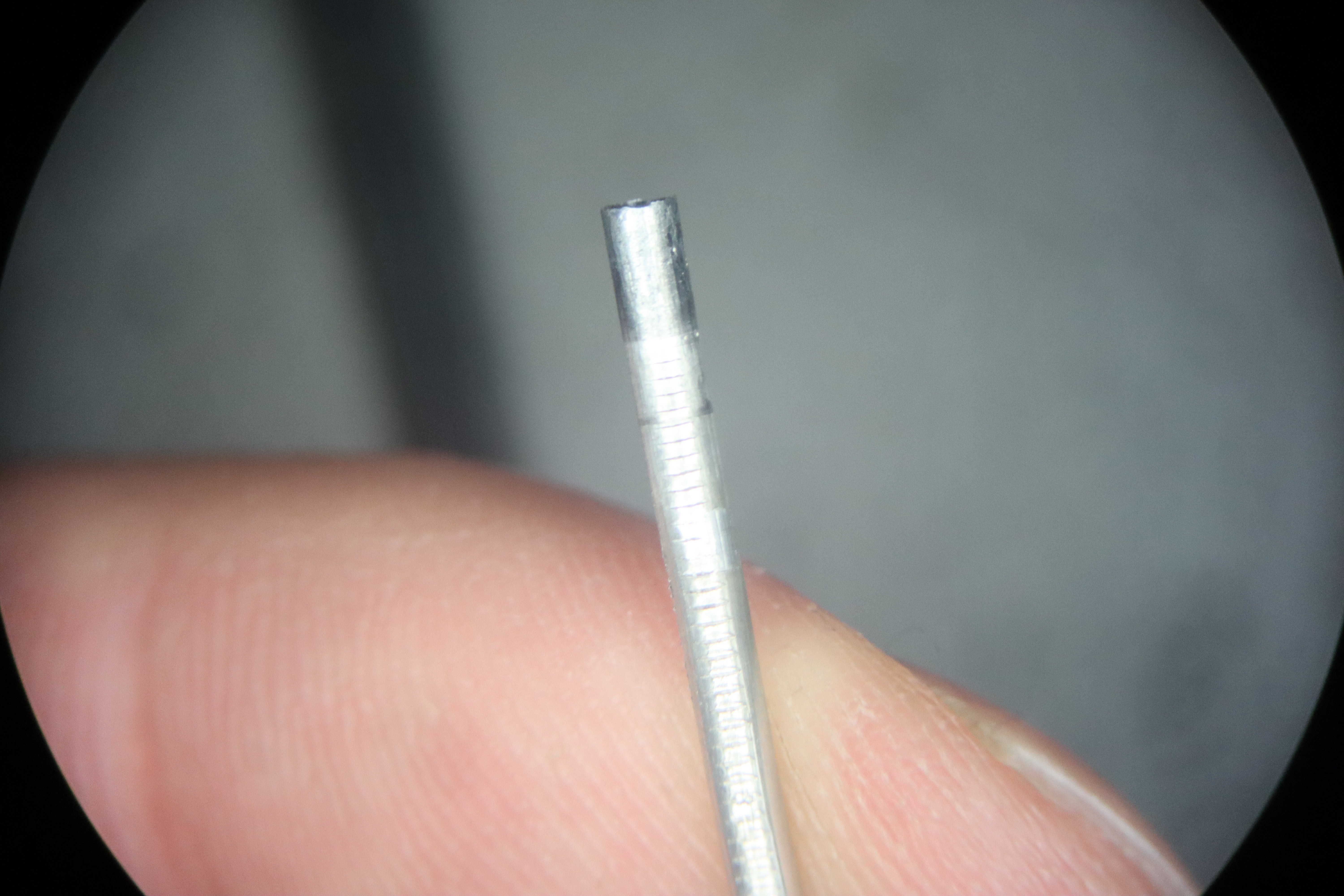
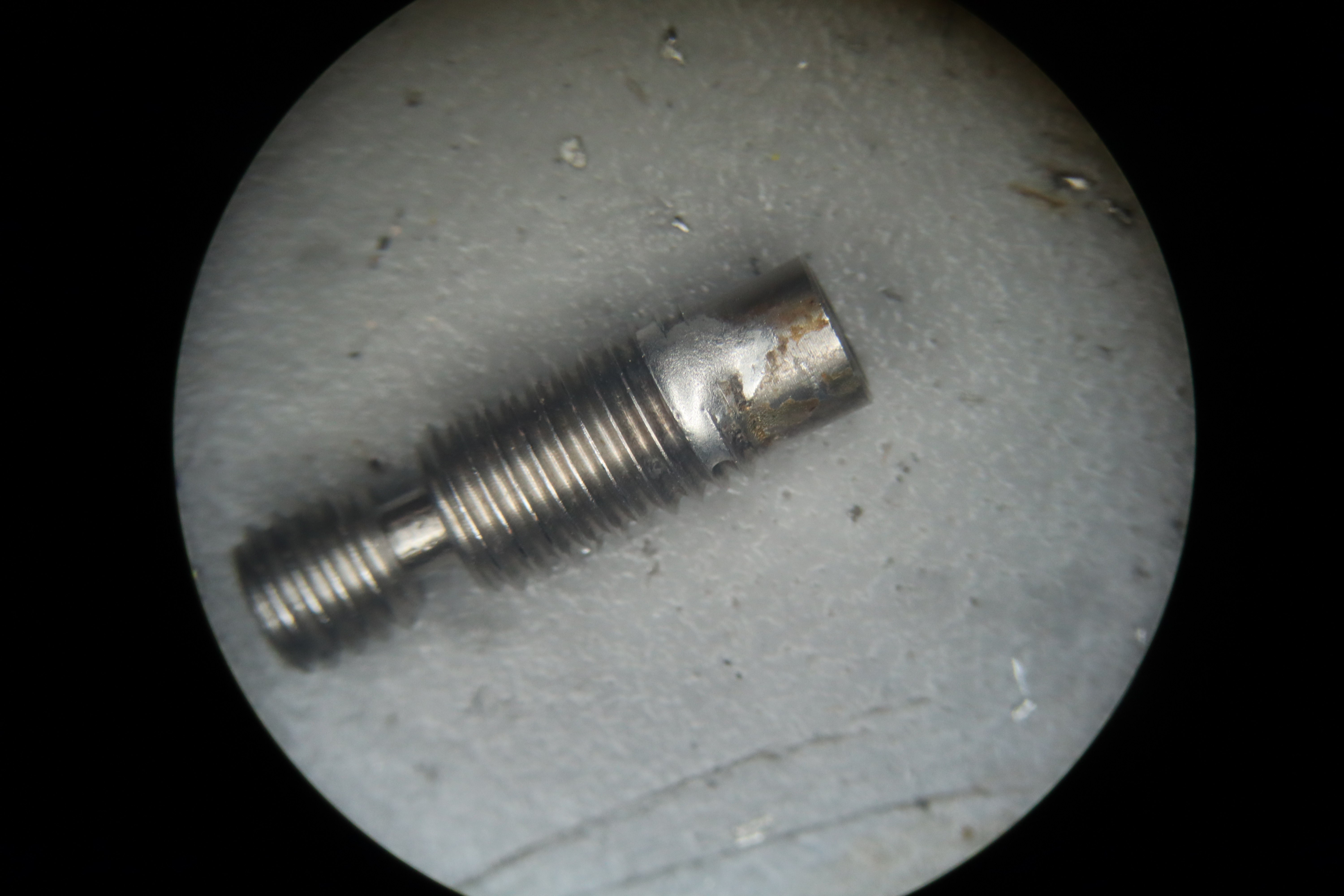
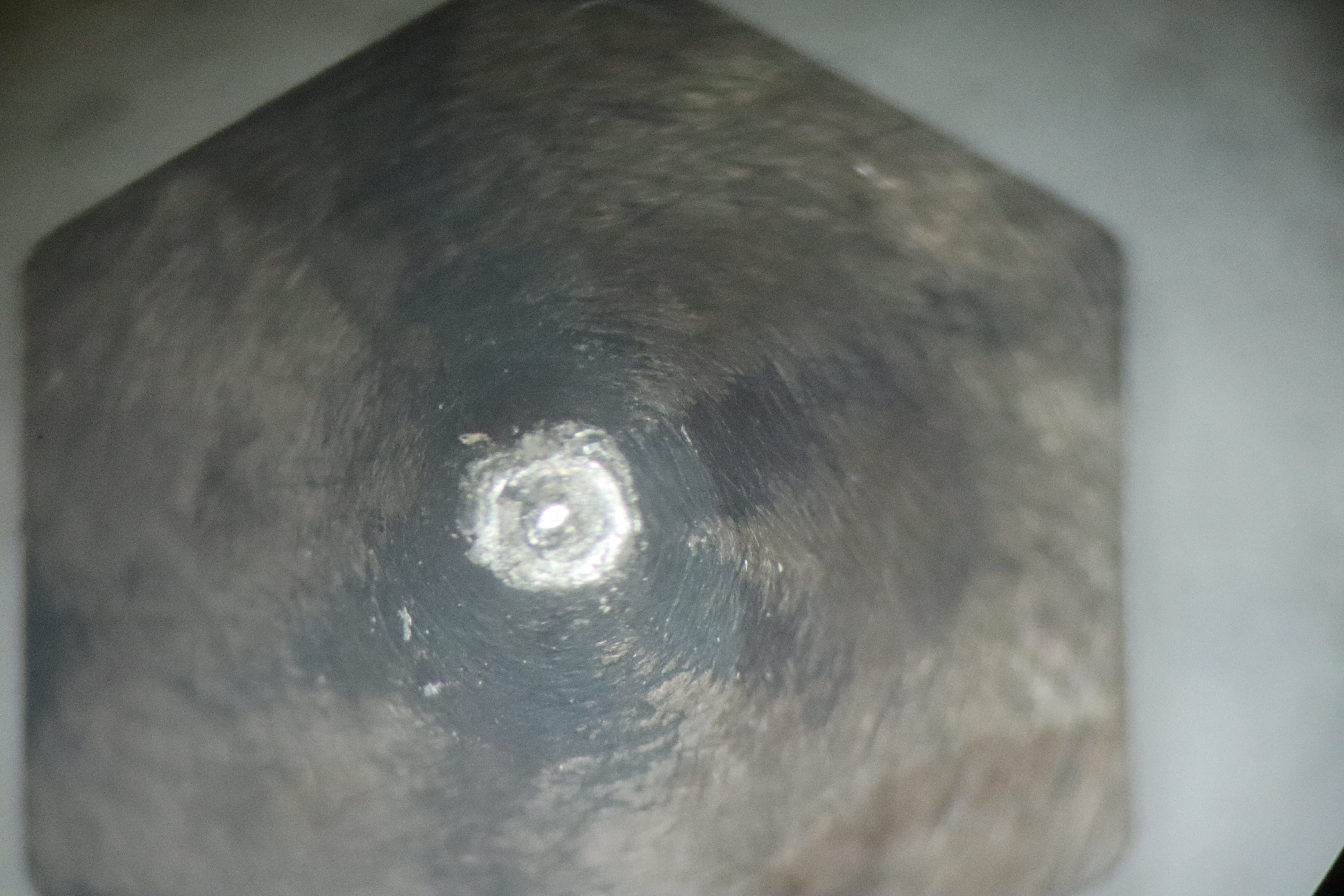
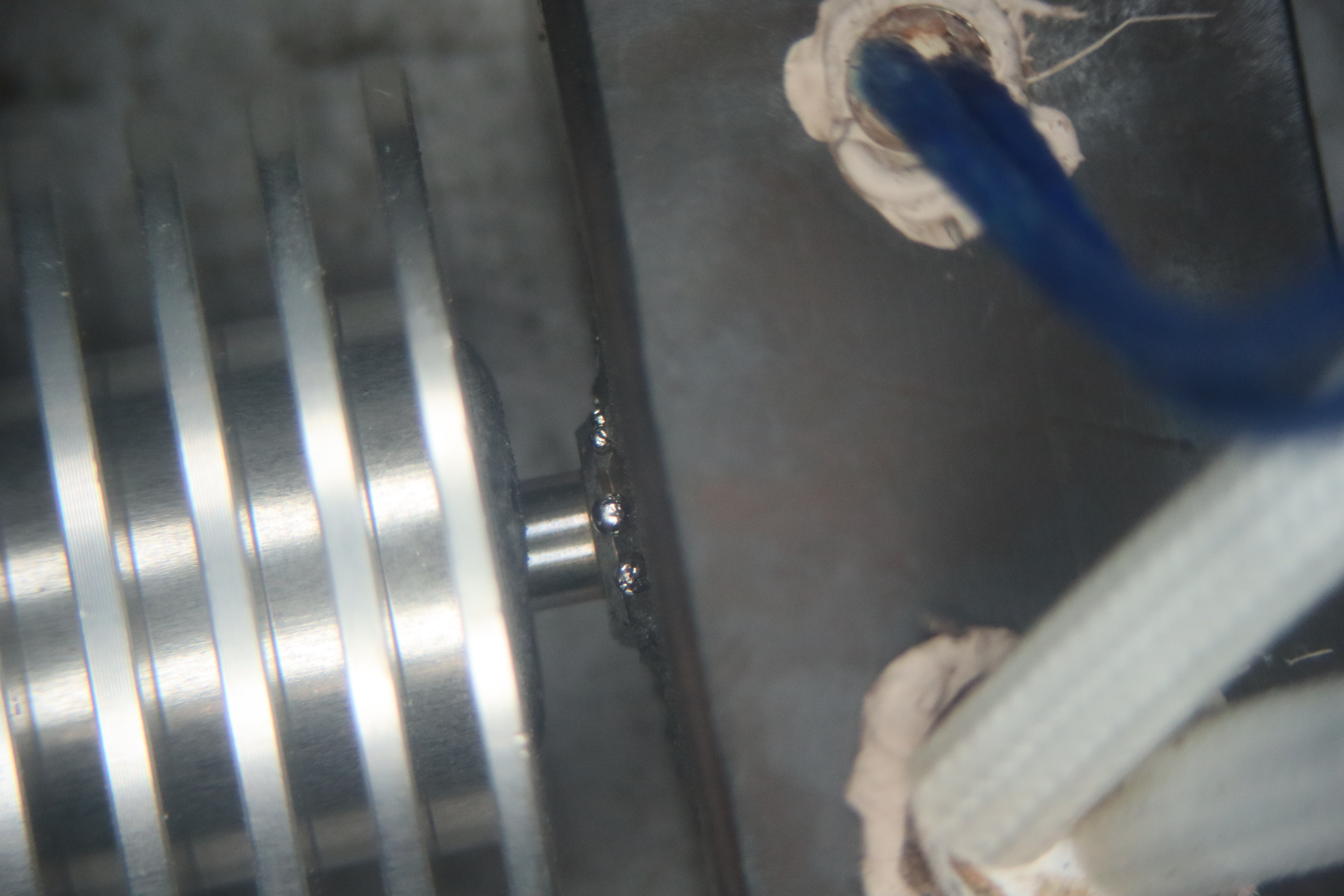
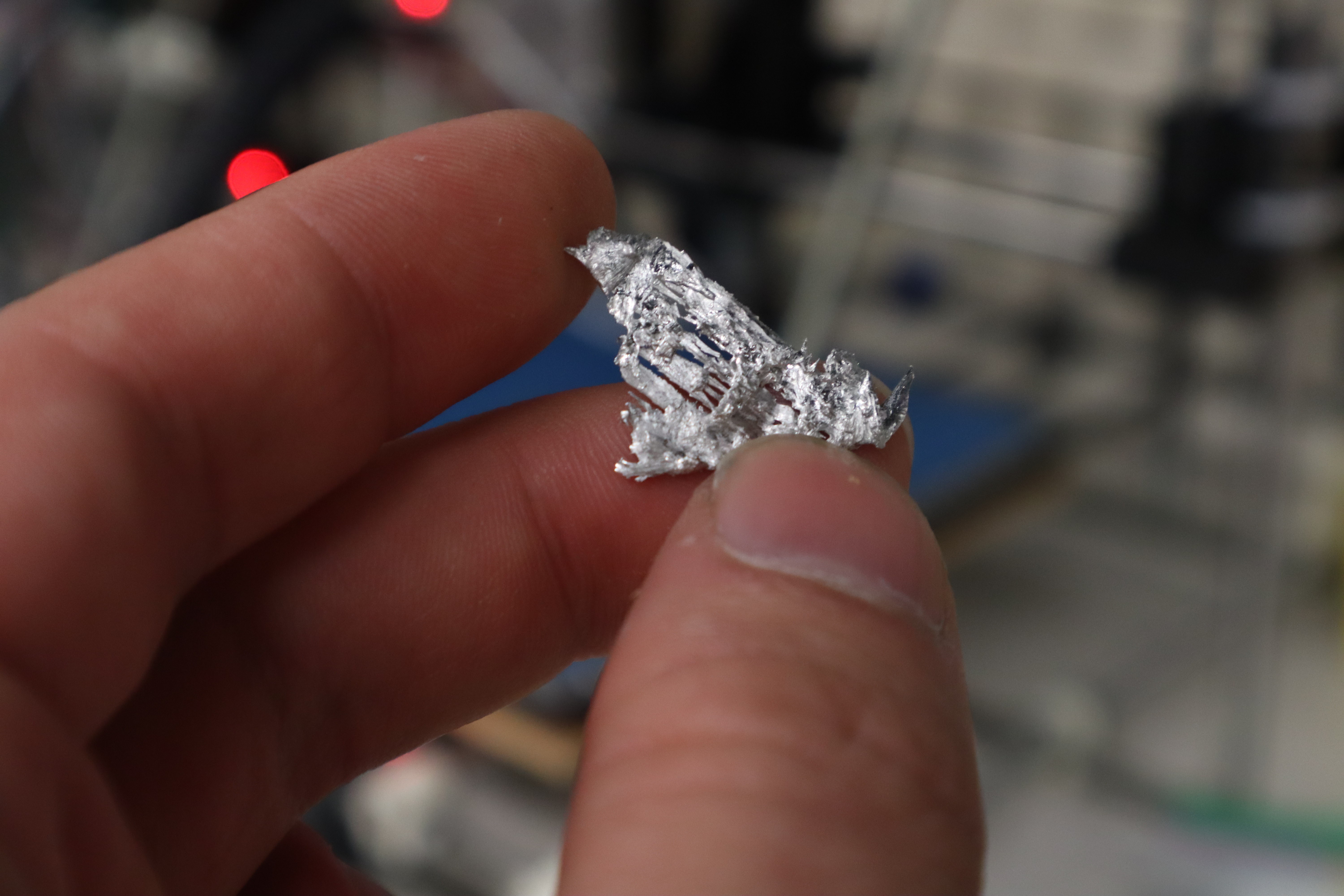
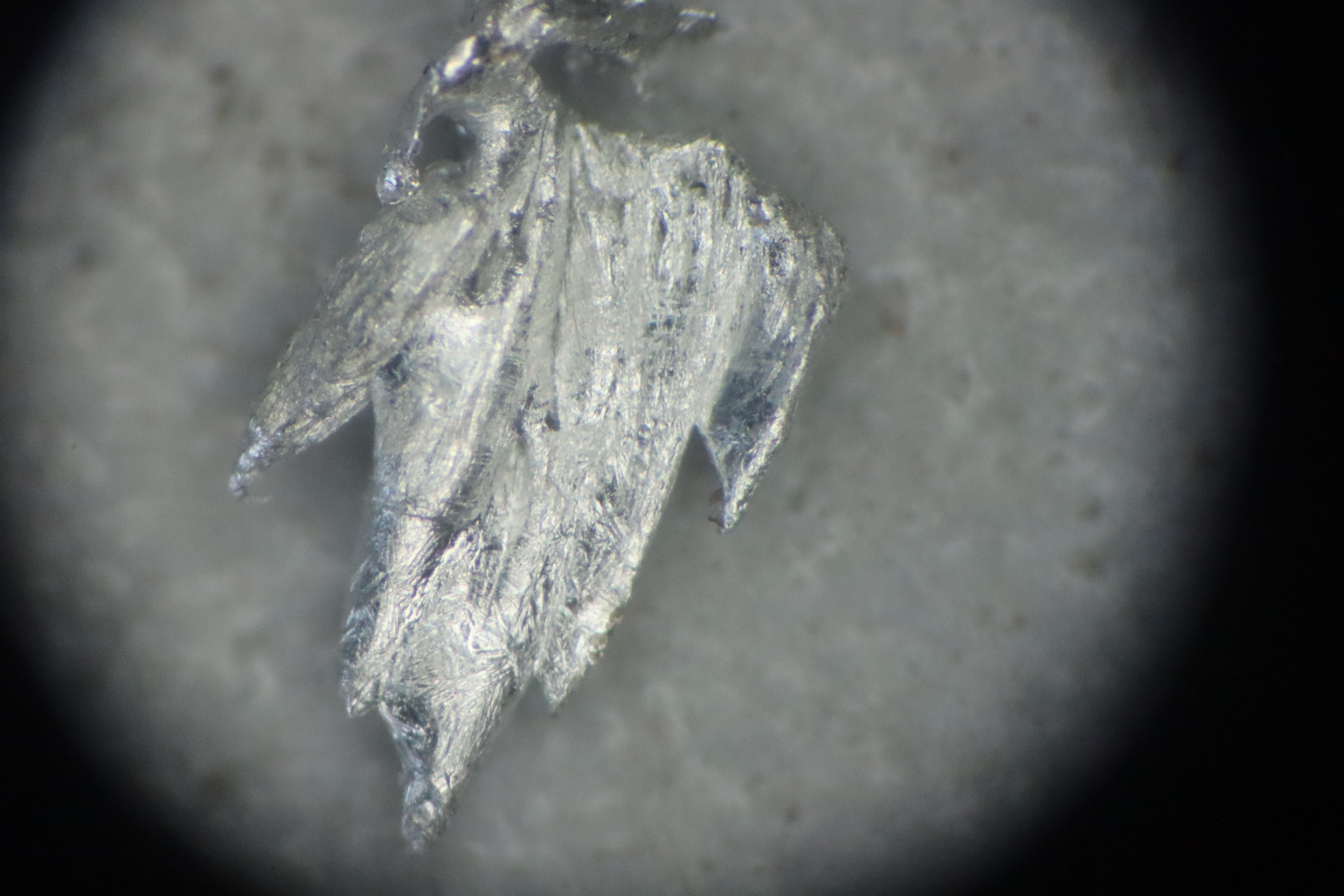
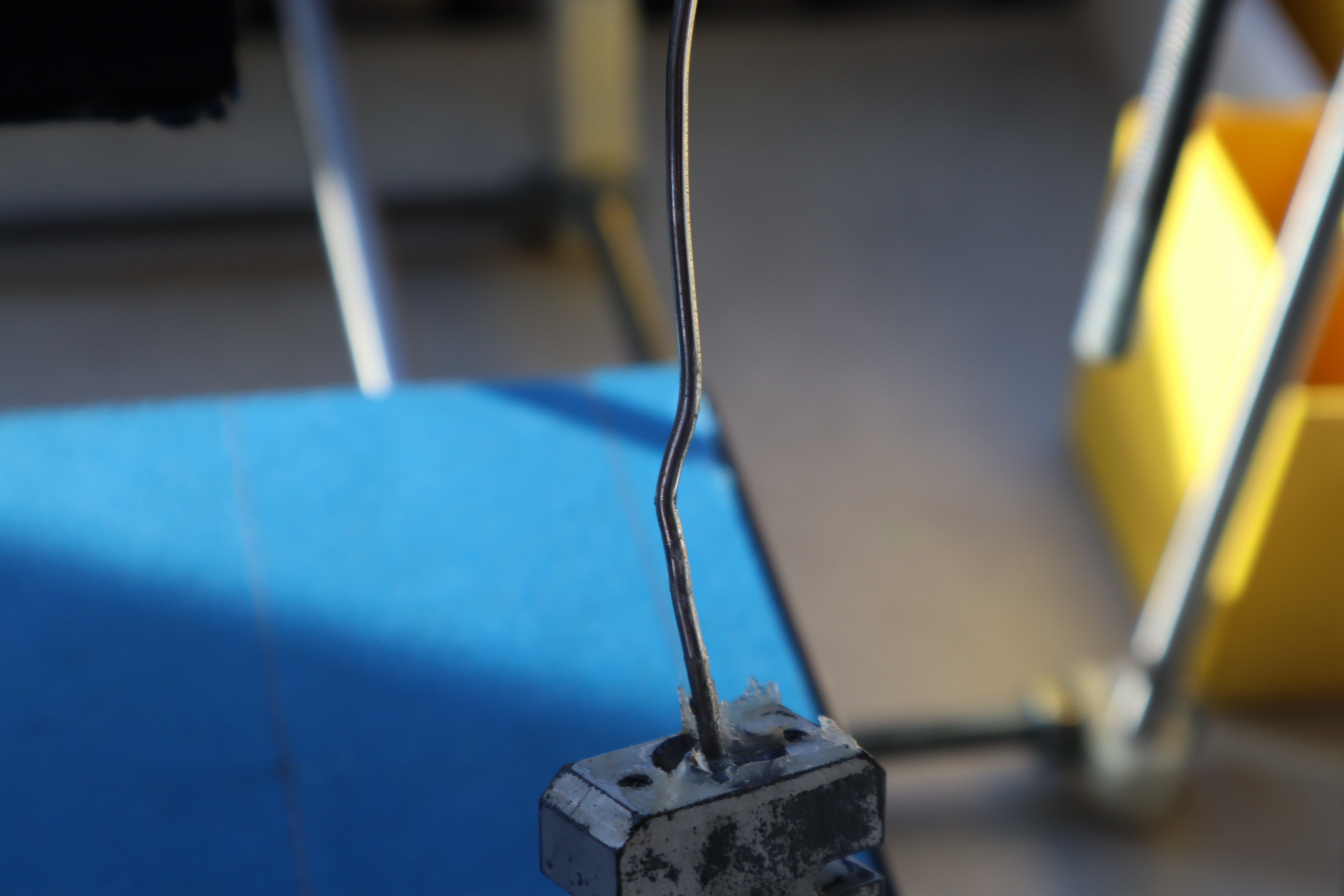
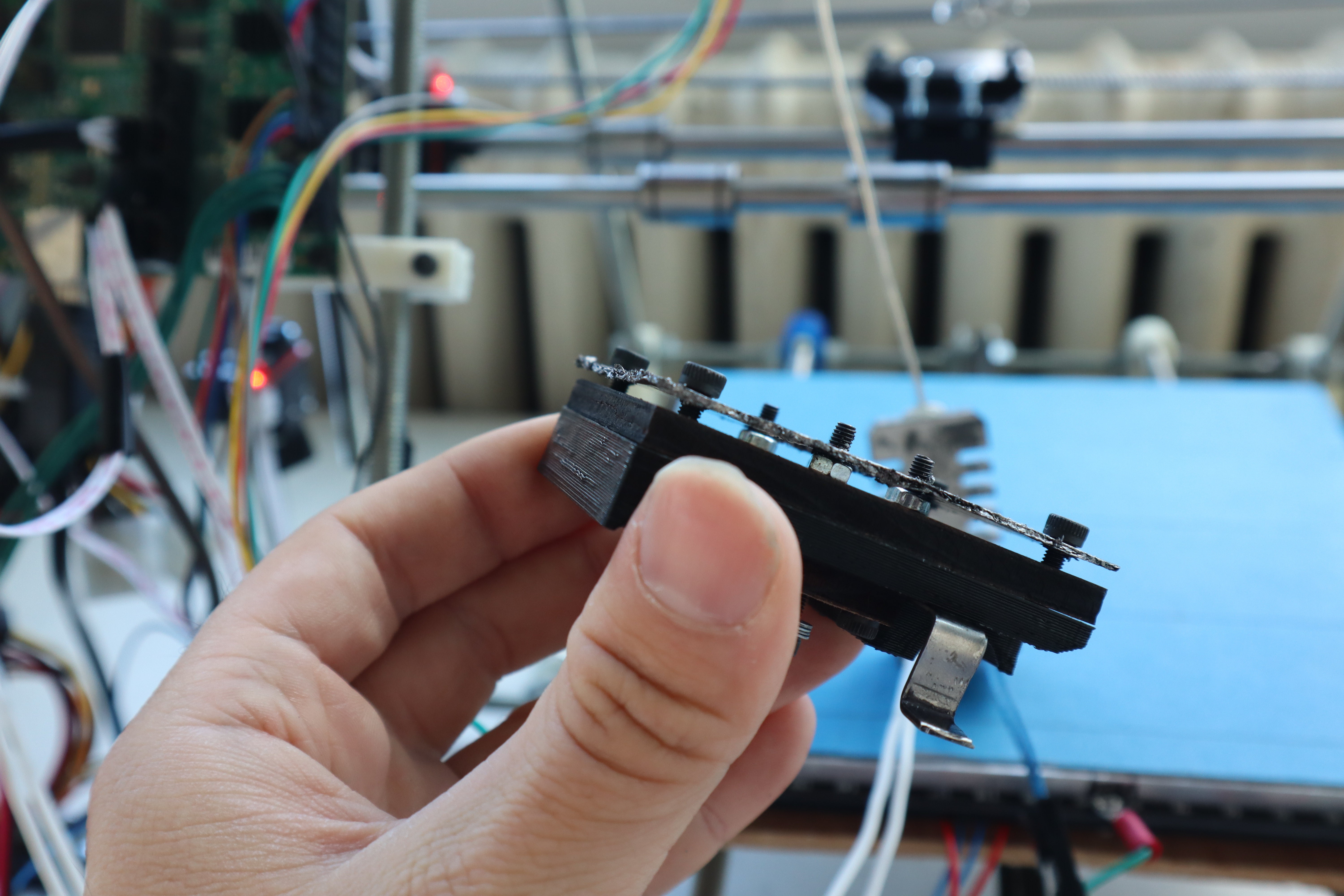
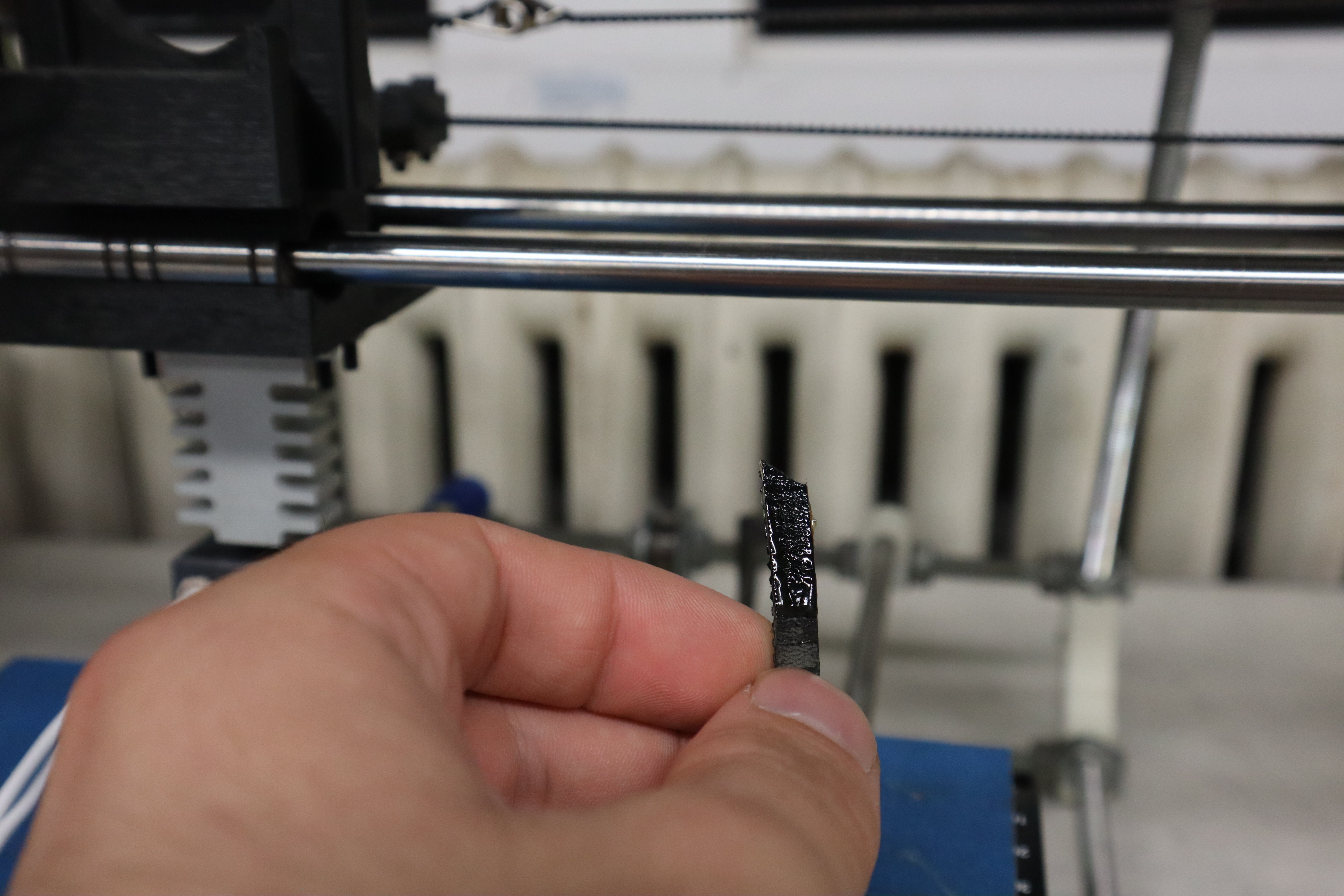
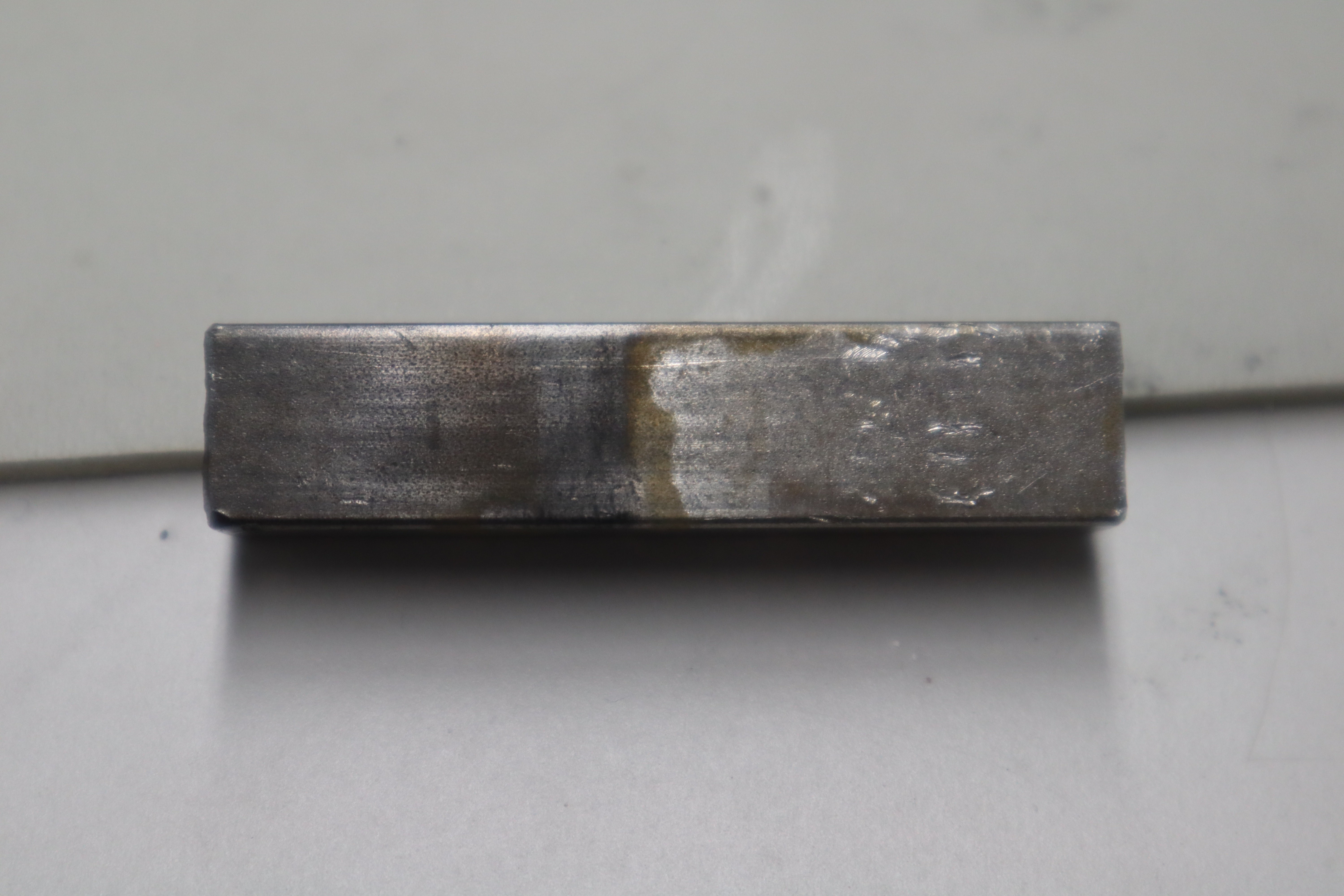
During granular jamming, the wire still got somewhat lodged in the titanium heatbreak, but upon inspection, no soldering occurred.
![]()
Where with the stainless steel, the darker section here would have been soldered to the heatbreak, here it was still possible to slide out. I also suspect that jamming only occurred once the nozzle had already jammed, allowing pressure to build up causing the wire to buckle where it was heated sufficiently for creep to occur. Hopefully once standard granular jamming is taken care of, we will see less of this failure mode. It’s a little disheartening to see that it can still happen, but I have many more ideas to try and mitigate that behavior in the future. 5.76mm of wire was mechanically stuck to the wall of the heatbreak and it still was possible to remove it by hand though, so I’ll count that as a win for MR-97 mold release. I suspect that the heat flows up the wire and causes it to creep, but then once it touches the cooler titanium wall, it solidifies a little more again. It would be fascinating to simulate this if I had the time and resources to do so. I’m not sure printing with oils or ‘liquid gaskets’ will prevent sticking, but perhaps some kind of porous surface with oil in it could?
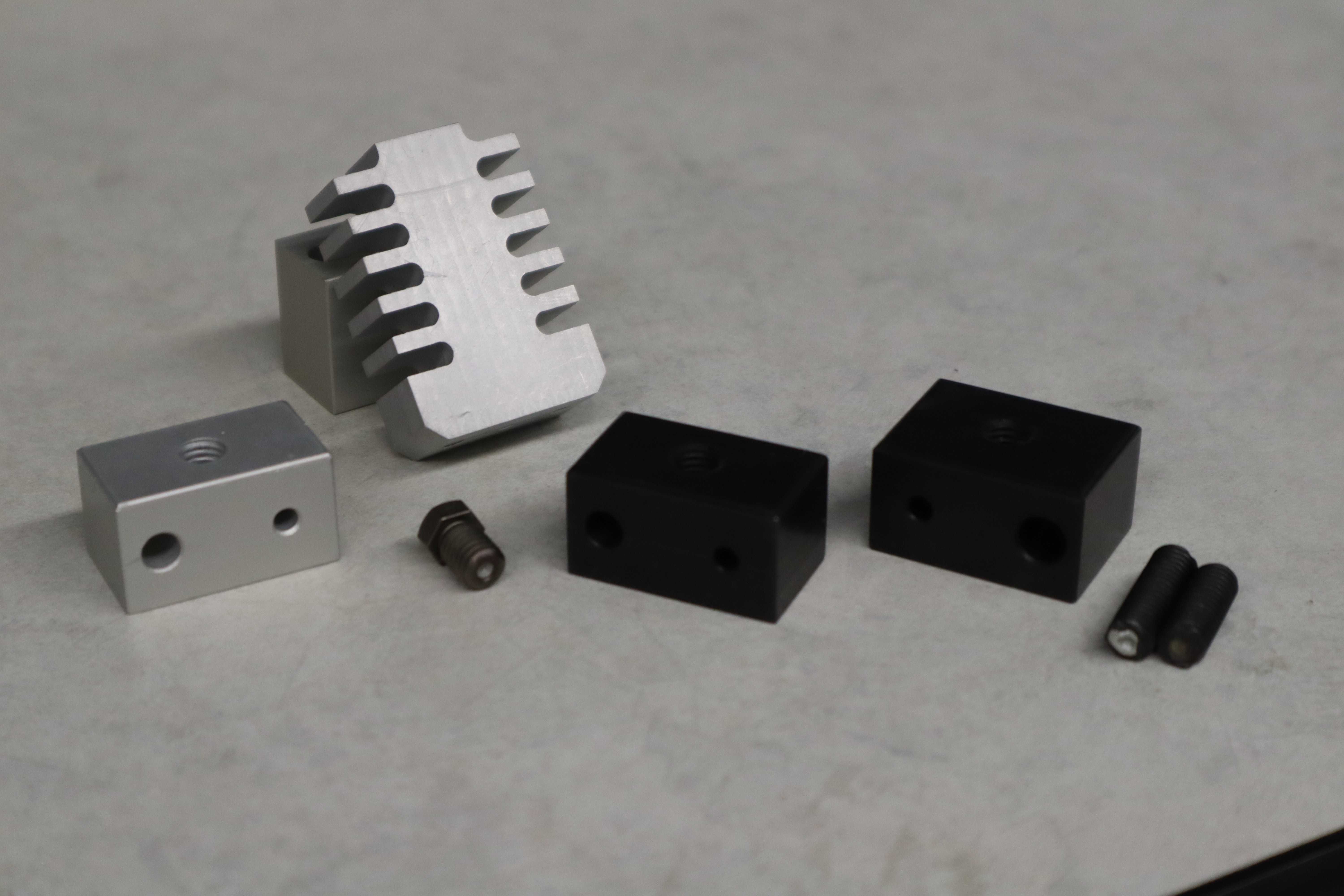
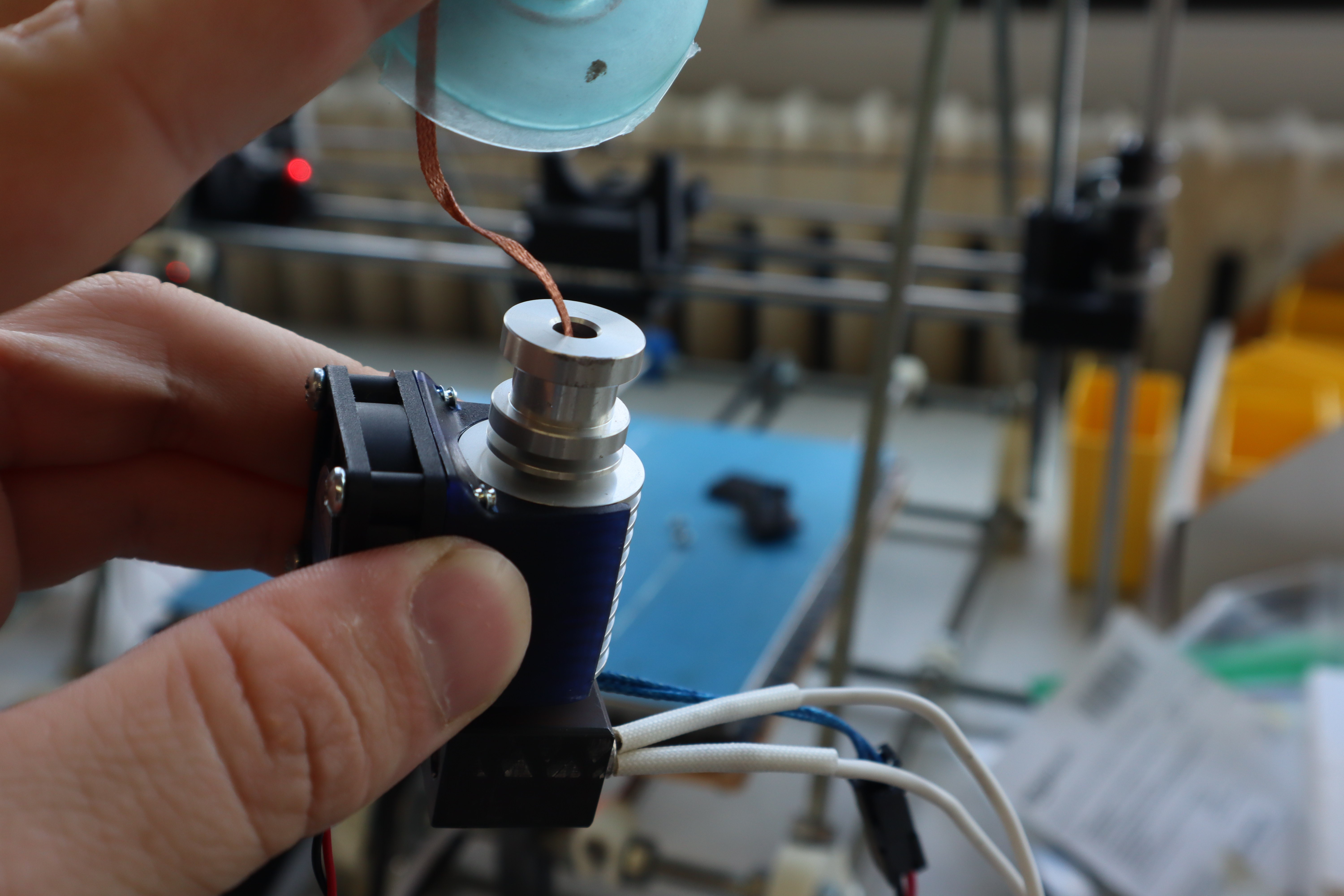
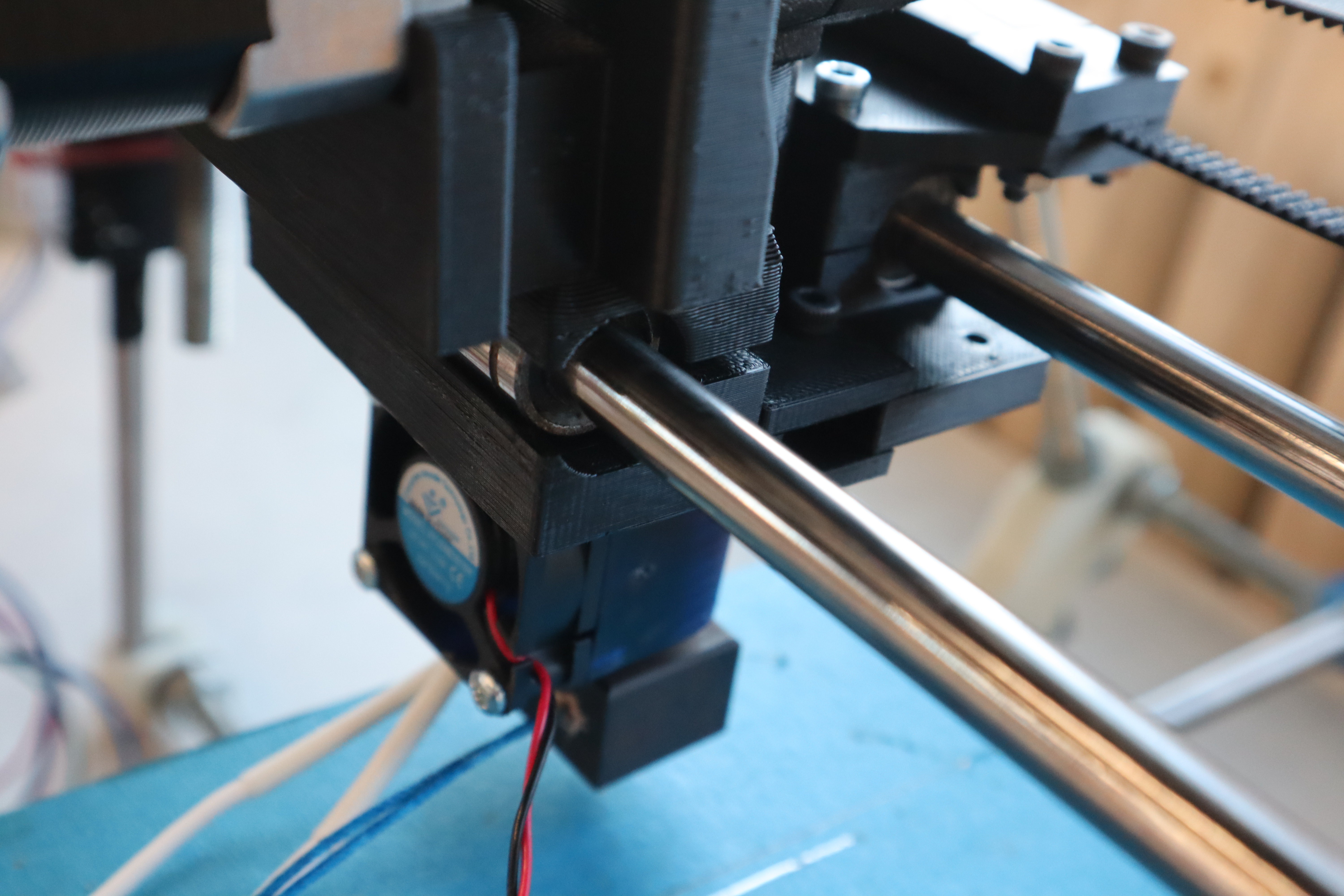
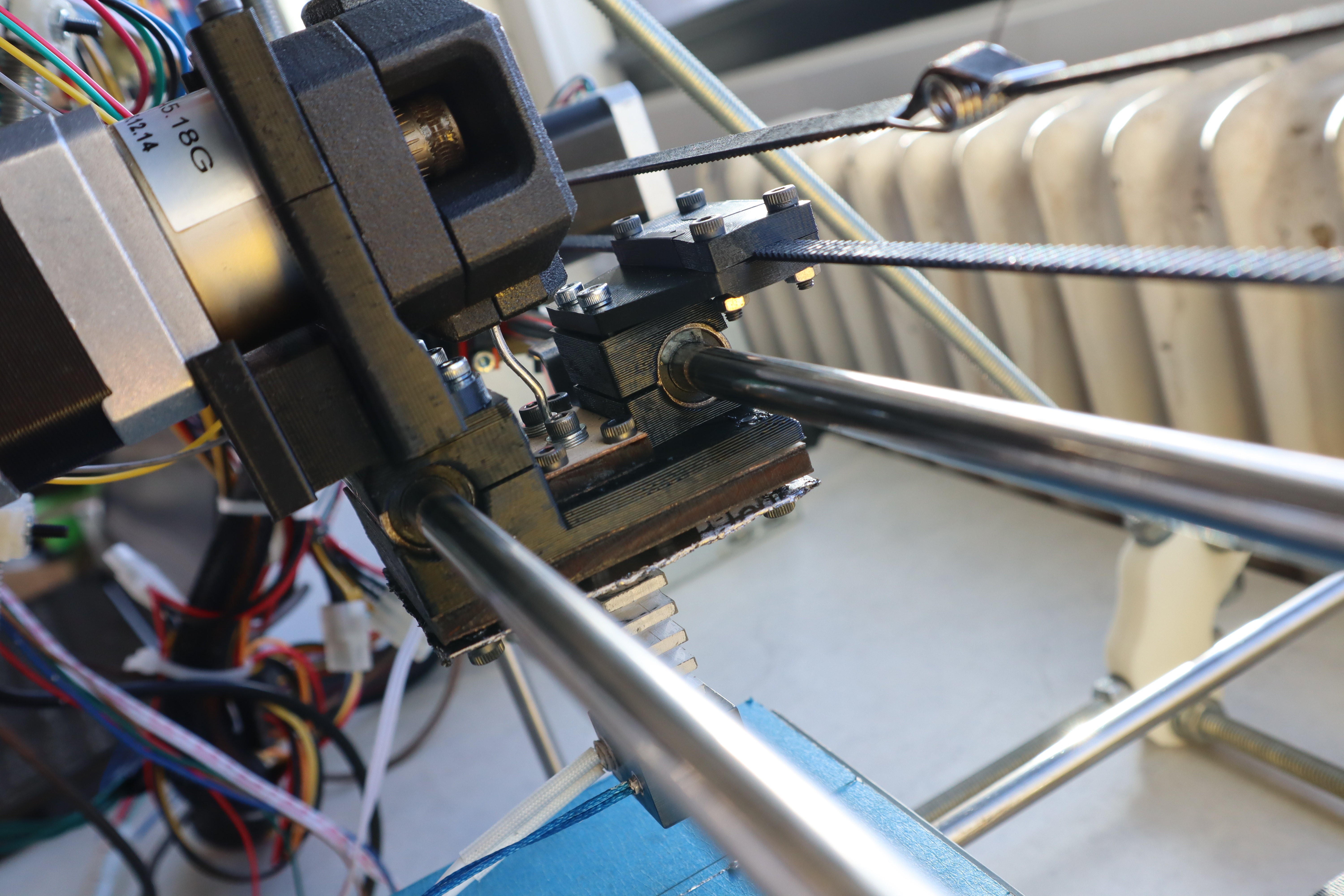
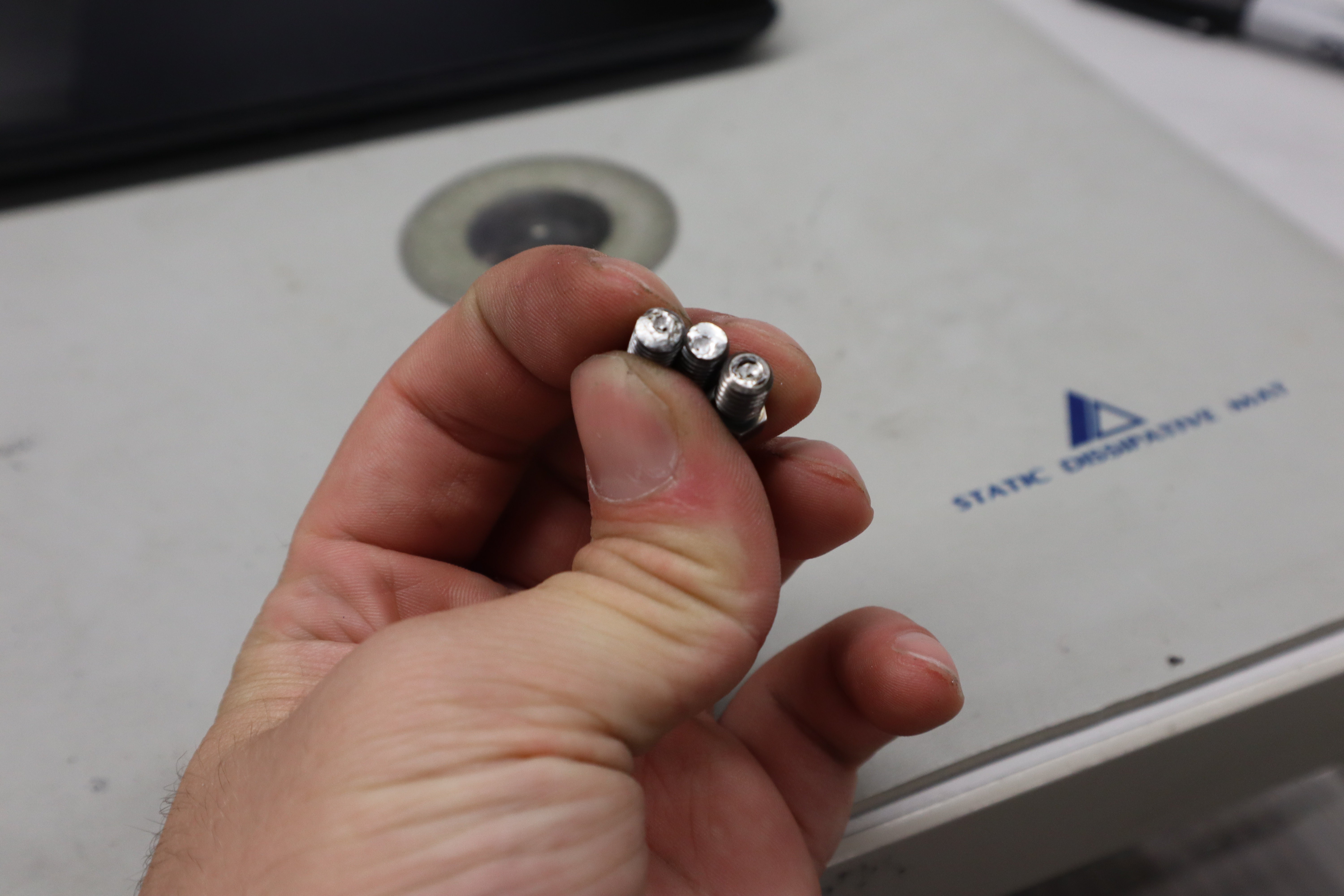
For this next design iteration, I tried to get the extruder in the best possible shape with respect to the results I got in the previous round: this meant trying to steepen the thermal gradient as much as possible, and making certain the fan duct didn’t fall off. I used the standard E3D fan duct and screwed on an adapter for a 40mm fan instead of a 30mm fan (in the future I might try something even bigger or with even higher airflow). Then I used an E3D bimetallic heatbreak, with low thermal conductivity titanium on the hot side and copper on the low side to maximize the thermal gradient. I also anodized the titanium surface to help prevent metalurgical bonding, and added a layer of MR-97 boron nitride mold release (a common metallurgical spray I highly recommend) to reduce mechanical sticking near the thermal gradient in the heatbreak.
![]()
(Anodized vs unanodized titanium heatbreaks. Depending on the coating thickness, some bright colors are possible.)
In the future, adding more internal geometry to the heat break could help prevent sticking while also potentially forming a good sealing surface.
![]()
I also insulated the nozzle with high temperature RTV silicone to try and keep the temperature of the nozzle tip as high as possible. I should also shorten the distance between the bondtech extruder and the nozzle, reducing the length of filament in teflon, but I suspect that’s a minor issue compared to the others. Finally, I replaced the steel heater cartridge with an aluminum one, to get a more even temperature across the whole block, and to help make sure enough heat was being transferred into the metal filament as it printed.
On the software side, I completely got rid of the large retractions during layer changes for now, in case that could cause jamming in the heatbreak. I might add it back later if I find retraction is unrelated, because it does tend to help. I also tried increasing the extruder temperature after the first layer instead of decreasing it, reversing the standard used for thermoplastic printing. Extruder max acceleration and jerk were both decreased 25% also, to help maximize the grip of the bondtec extruder on the filament before stripping, in case that could help it push through a slight jam. I also increased the printing temperature to 300C and adjusted the thermistor table by measuring its behavior against a known thermocouple on a high end soldering iron to allow it to work at those temperatures.
![]()
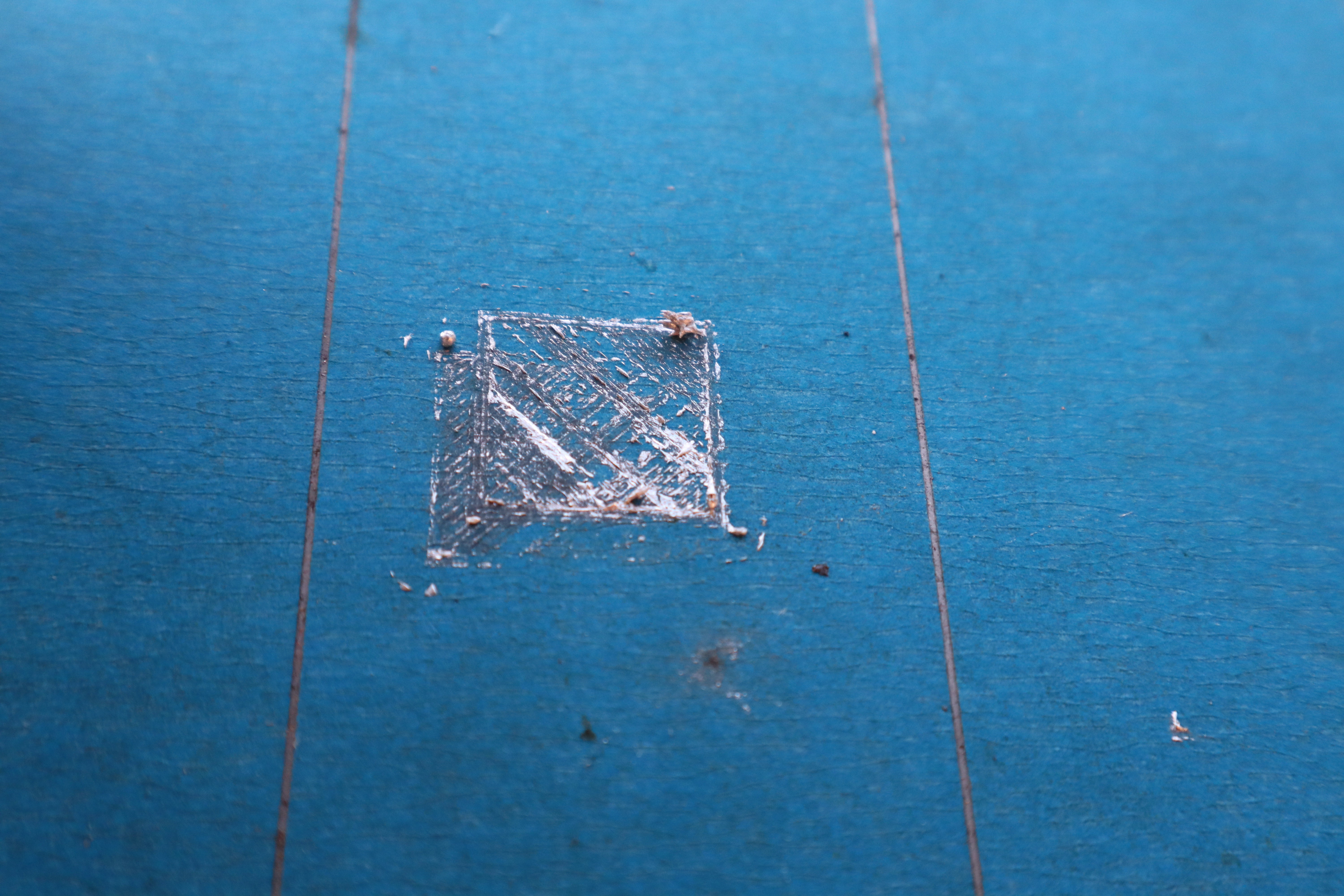
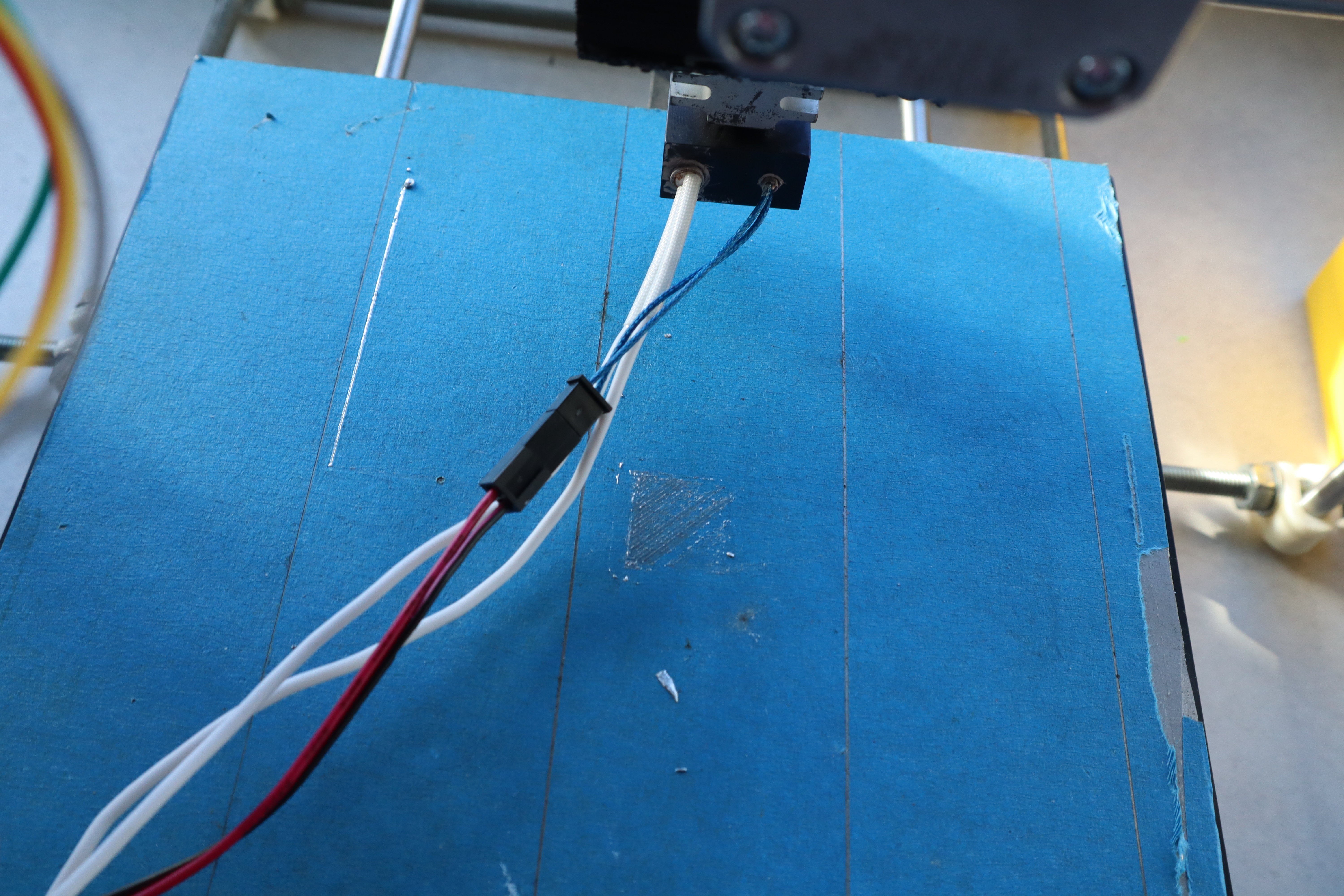
I’ve also been noticing that bed adhesion isn’t really good enough on blue tape to get a reliable first layer, so I’ve tried out a number of different substrates to improve first layer quality, and I ended up with spring steel substrate, which was good enough. It wets to the tin-zinc reasonably well without bonding strongly to it once it cools down, and isn't anything exotic, delicate, or difficult to work with.
![]()
I coated the spring steel print bed directly in tin-zinc to maximize the first layer adhesion during the next few tests, but in the future, a thin layer of solder flux sprayed on like hairspray might be usable for the same purpose, while also being far easier to apply. Or perhaps I could get spring steel galvanized, although it doesn't usually come that way.
![]()
The new temperature sensors will be added shortly, and once I increase the printing temperature, the rest of the system will hopefully finally work. If not, then I'll try the wider nozzle and perhaps add steel bristles to help direct the fluid flow. A solution is certainly close at hand though.
-
R.I.P. Sanjay Mortimer
12/12/2021 at 00:00 • 0 commentsI recently learned Sanjay Mortimer died...
I kept in touch with him and said hi at pretty much every Midwest RepRap Fest since 2015; He was an amazing person, and a great friend. My condolences to the E3D team for his loss; I've always thought of him as their Steve Jobs: excellent when communicating with customers to describe E3D's capabilities and envision what people would want next, and good at nurturing fledgling technologies like this one.
A little known fact about Sanjay was he and the E3D team worked in collaboration with a bunch of companies (I'm not sure I should name them here) on Semisolid Metal Printing. As I understand it, those projects were abandoned though. The last time I saw him, at this year's Midwest RepRap Fest (remotely via computer), he called me a hero for keeping up this work when so many others had given up. This one's for you Sanjay! I'll get this technology working soon enough, in your memory. I only wish you could have seen it in your lifetime.
-
A separate jamming issue
11/25/2021 at 18:01 • 0 commentsCareful application of the X-Pando to the male threads, and replacement of the glycerol-borax flux with glycerol-zinc chloride flux removed the clogging issue at the nozzle, but now it appears that there is a new issue:
![]()
As the wire approaches the heatbreak it softens and widens , apparently becoming semisolid. It then apparently mechanically sticks to the wall of the heatbreak. The length of material that does this seems a bit longer than the heatbreak itself, suggesting that most of the heat is being conducted along the metal wire. This means that the thermal gradient will be less steep than we would expect from thermoplastic printing, which means E3D's design would ultimately need to be re-optimized for metal printing; something I had hoped to avoid. I increased the clamping force to try and avoid stripping, but it still got stuck this way. Perhaps I should also reduce maximum acceleration of the extruder, to help prevent stripping, but the better thing would be to figure out the cause of the jamming
![]()
I poked around in the nozzle with my 100 micron tipped engraving bits but found only metal this time: no nonmetallic blockages this time. If the temperature gradient at the nozzle tip is too steep, then perhaps granular jamming is occuring at the tip, but the melting point of this alloy is at least 20 degrees below the steady state extruder temperature when not in contact with a surface. When subsequently lifting off the surface, the blockage should re-dissolve readily in the alloy, allowing for extrusion again, but that's not what I observed: once it's clogged, if you cancel the print and move the extruder up in the Z axis, it remains clogged. There is a chance I am wrong about the temperature at the nozzle tip, so I will investigate this further
![]()
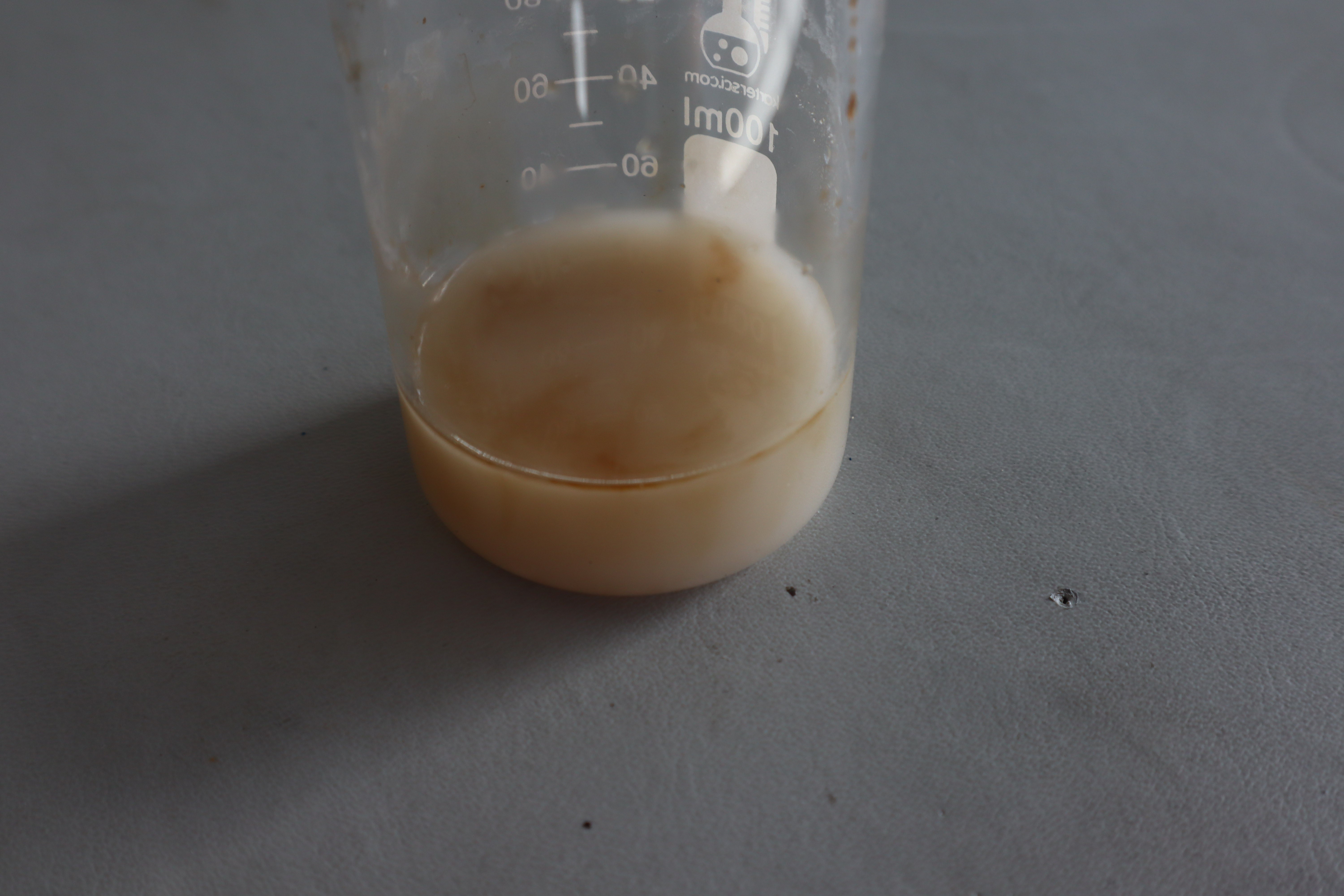
I also noticed something else: the glycerol-borax solution I've been using had some aluminum hydroxide powder I mixed in then forgot about for a while. If it were a glassy material we would expect it to be clear
![]()
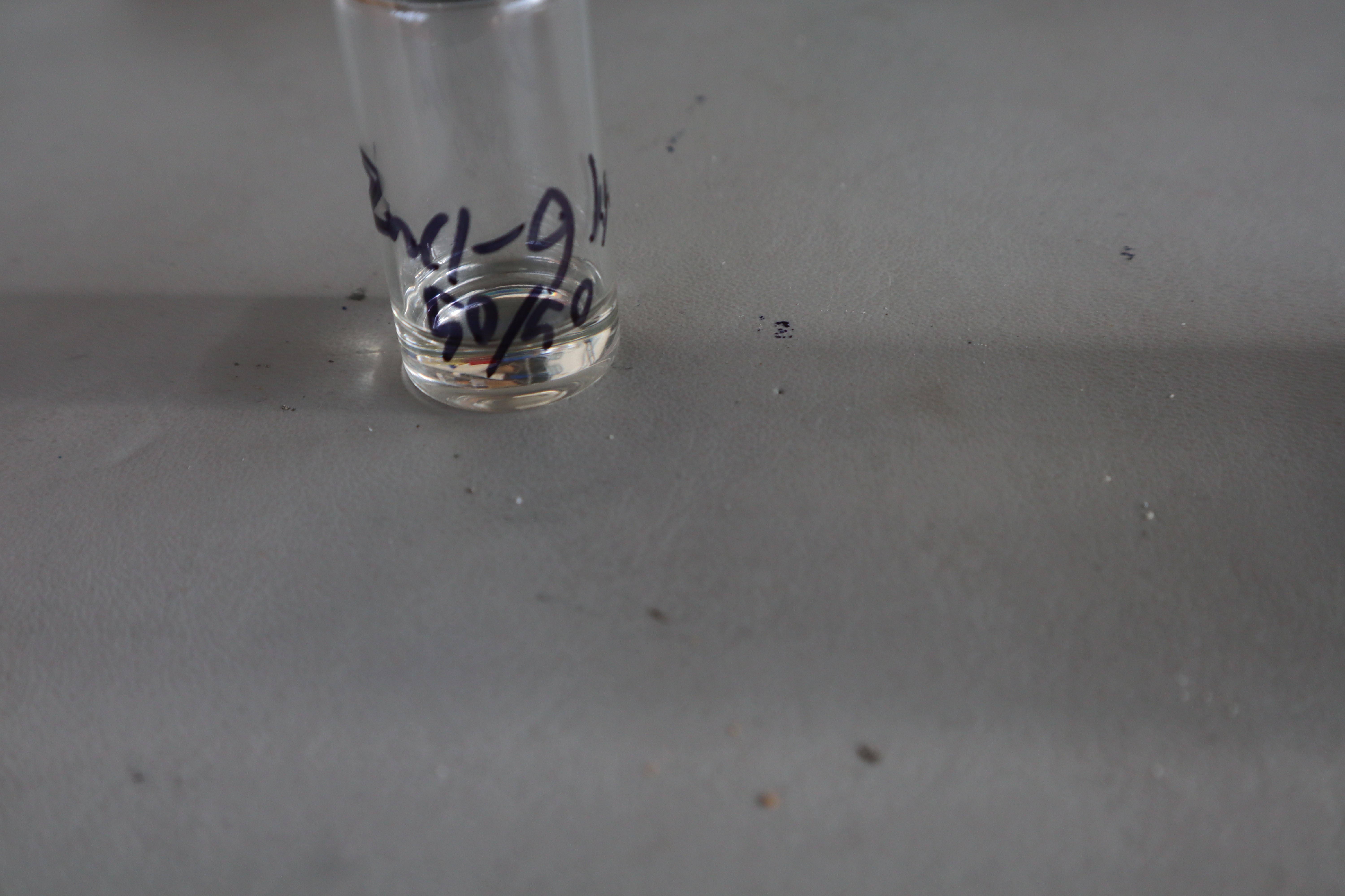
The zinc chloride/glycerol deep eutectic solvent was clear for example, though highly viscous with the 50/50 wt% combination I used. I bet this deep eutectic would be excellent for rechargeable zinc batteries: that viscosity would really help reduce dendrite formation.
But back to the jamming issue, I realized that the zinc chloride could have caused the tin-zinc to solder to the stainless steel, so I tested it:
![]()
And indeed, the glycerol-zinc chloride acted as a flux which made the stainless steel solderable by 80/20 wt% tin-zinc. I'm sure this is useful for a number of projects here on Hackaday. It seems to allow soldering to freshly abraded surfaces better than surfaces that have had time to develop a stable oxide layer.
With the knowledge that metallurgical bonding might be happening instead of just mechanical bonding, I realized that the molten metal was probably slowly creeping up the heat break and solidifying. Moreover, in thermoplastic printing it is standard to decrease the print temperature after printing the first layer: this could also cause jamming by allowing some of the print material to solidify higher up in the heatbreak as the temperature decreases. In all subsequent tests, I increased the printing temperature instead of decreasing it, but the jamming still occured. It's possible that long retracts could also pull liquid metal further up the heat break and allow it to solidify. In any case, zinc chloride is definitely a bad choice for this design, so I replaced it with just glycerol, which is still viscous enough to seal the surface when in the cold end.
![]()
Unfortunately the X-Pando bonds too well between the heatsink and the heat break to be able to take them apart without damage, so I tried heating up the nozzle and wicking up the tin-zinc, but it was apparently fully solid in the heat break while at 300C. I drilled out the old one and tried to use it again with glycerol and an increased printing temperature after the first layer instead of a decrease, but it just jammed again, probably due to the wetted section of the heatbreak. If I could take these apart I could remove the wetted surfaces of the heat break with a hot tank bluing session. Ultimately I had to use a new heatsink and heatbreak.
I got some silicone O-rings that function up to 300C from McMaster: I'll give these a try as a sealing surface and try this without a liquid sealant, then just glycerol again with a fresh heatbreak.![]()
I've also got a titanium heatbreak on the way, as well as a bi-metal heatbreak from a titan aero and a bigger fan to upgrade the cooling on the heatsink. I know for sure that tin-zinc won't stick well to anodized titanium, reducing the friction at the heatbreak. And the other components will help make the temperature gradient across the heatbreak steeper, to compensate for the higher heat conduction through the metal filament. Hopefully that will be enough. I have a few other ideas for sealing to try: a sprung sealing ring like in a gasoline motor piston, a wire drawing die profile which seals to the solid wire and widens again as the wire softens into its semisolid range, teflon inserts to prevent sticking, oils with corrosion inhibitors so that they better separate the heatbreak from the alloy wire. I may also experiment with altering the gear teeth on the bondtec extruder so that it grips better without stripping the wire, but hopefully that will not become necessary. There are probably a number of software settings I can play around with in Marlin and Prusa Slic3r. In case the nozzle is actually clogging via standard metallic granular jamming, I should also try heating the bed to the highest possible printing temperature
![]()
By the way, I've got a handle on cleaning the threads: an important step when re-applying X-Pando. Just add a bit of soapy water and thread a screw through the surface and lever it around to scrape the threads. I also went over the threads afterwards to pull out any tin-zinc that managed to get through. I have found that when re-applying the X-Pando, you want it to be a more paste-like consistency, not thin and runny. Otherwise the tin-zinc leaks through the threads more easily.
![]()
There we go: all clean, more or less. I also drilled down into the nozzle again to make sure it wasn't clogged by any remaining X-Pando debris, and I found nothing this time: it was all metal.
-
Jamming issue fixed
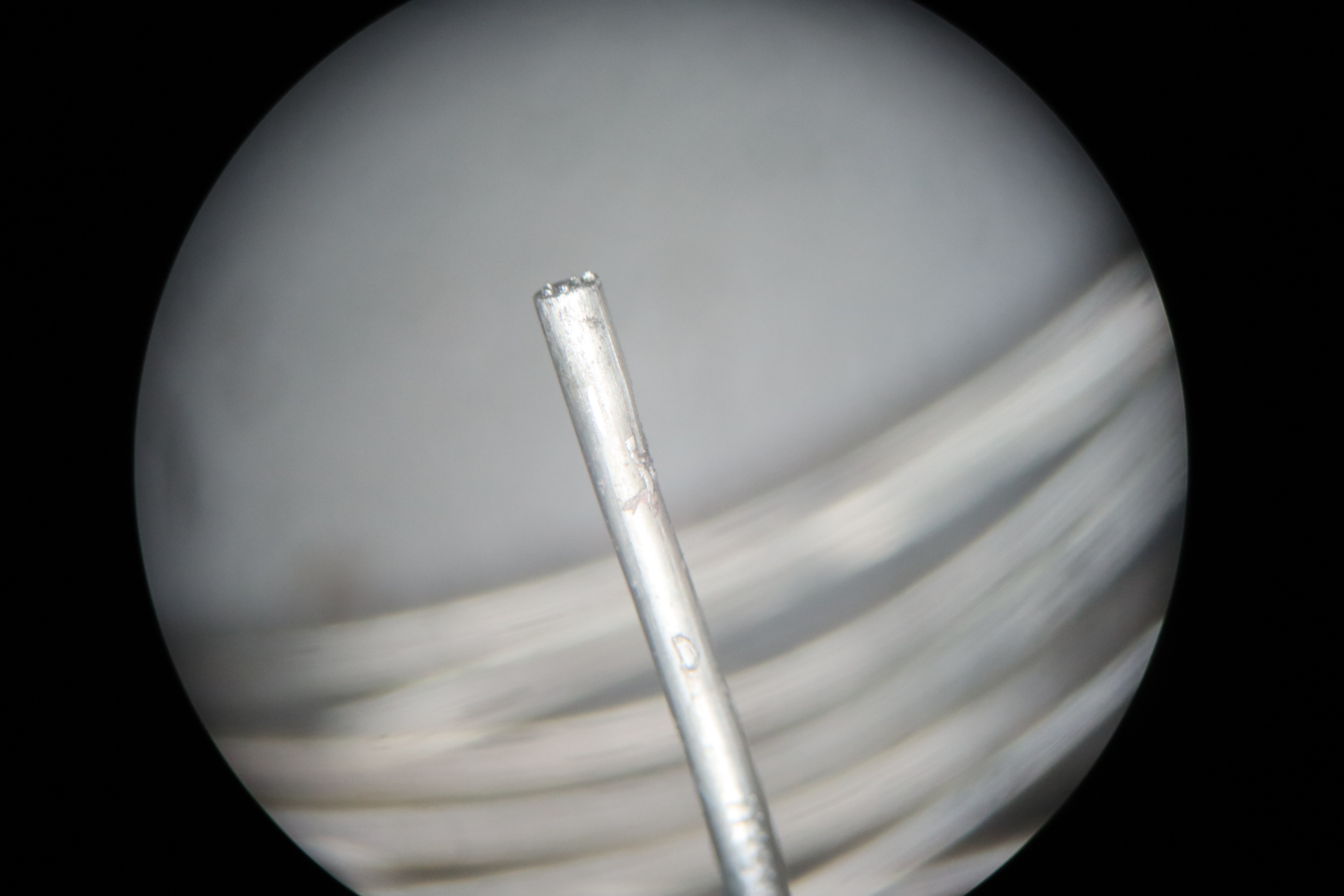
11/15/2021 at 23:06 • 2 commentsLast project log, I ended with another jamming issue. This time it turned out to be pretty standard jamming compared to the last jamming issue. Even just looking at the nozzle under a microscope, it's easy to see a bunch of nonmetallic stuff there.
![]()
And just to be thorough, I tried removing the filament while the extruder was hot, and it removed and re-inserted nice and cleanly, with a clear and stable interface between the glass gasket-wettable section and the metal-wettable section, enforced by the steep temperature gradient and patterned wettability at the interface. It wasn't so easy to capture with my camera, but was perfectly visible to the naked eye. You can kind of make out the smooth surface of the liquid metal though.
![]()
And I was in for a little surprise too: apparently this tin zinc alloy expands a little bit as it cools: it must have expanded enough to produce 5000 PSI of pressure in order to leak through the X-Pando like that and form droplets. Later on when printing again though, even with no servicing to some of those joins, the leaks did not continue at lower pressures. I imagine the capillary pressure developed at those tiny radii plus in conjunction with the surface tension of the metal in the cracks is immense enough to keep them sealed under normal operating conditions. What surprised me though is that metal came out here, but nothing at all came out of the nozzle. It must have been extremely clogged.
![]()
Speaking of the nozzle, it was time to figure out what went wrong with it. I slowly machined down into it, checking things out as I went
![]()
As I got deeper into the nozzle, it became obvious that there were little nonmetallic specks throughout it. I was pleasantly surprised to see so few air pockets, because one failure mode I was worried about was getting a large air pocket lodged in the nozzle, which would have made extrusion very difficult to control. Maybe it was just because the thing was at at least 5000 PSI though?
![]()
From looking at the chips directly, it's obvious that there are little grey or black nonmetallic specks in there. I hypothesized that these were bits of X-Pando that had leaked into the metal, because I had applied the X-Pando to the female pipe threads instead of the male pipe threads, which would have tended to push the X-Pando into the liquid metal instead of out to the nozzle.
![]()
This was easy enough to test: I just added some wet X-Pando to the female threads, threaded the nozzle on, then removed it, and Viola! The X-Pando was all on top of tinned surfaces that would have liquefied when the nozzle was heated next, releasing that material to clog the nozzle. I thought about other mechanisms that could have caused a clog, and three came to mind: particulates in the actual metal wire, a reaction between borax from the liquid glass gasket and the zinc chloride in the Sta-Clean flux I had used to make the inside of the nozzle so wettable, and standard semisolid granular jamming. Particulates in the metal wire would be unlikely, because I kept it well away from wettable metals and metal powders like copper, iron and nickel as I made the wire, and because surface chemistry would have caused any organic contaminants to keep to the surface of the metal, where they would have popped out or at least become visible during wire rolling. I have no reason to suspect that the clog was related to borax reacting with zinc chloride at the moment, but perhaps I will consider changing the glass gasket recipe in the future to use lewis acids instead of bases. But for now, it seems all the liquid gasket material floats nicely on top of the molten metal and doesn't get pulled down through it appreciably. Nevertheless, it's something to watch out for. If the X-Pando hadn't caused the clog, granular jamming probably still would have: I realized as I was going over these things that the alloy I made had 30% weight zinc, when I needed 30 atomic percent, which would have been 19.1% by weight. So I reformulated a new alloy and drew it into wire, but I made one mistake in that process, which I will discuss further below.
![]()
Before I did this test though I cleaned out the nozzle thoroughly to hopefully keep it from jamming again, Drilling got most of the alloy out, but left a thin layer on the walls and the bottom. I tried heating the nozzle up and banging it on the table to shake out the remaining metal, but it was wetted strongly to the surface so most of it remained. I couldn't even see what had clogged the nozzle. So then I got creative. Luckily for me, The M2 Molybdenum tool steel Micro Swiss makes their hotends out of is rather resistant to attack by gallium, so I melted some gallium into the top of the nozzle, heating the outside of the nozzle with a soldering iron (don't touch gallium to soldering irons, it kills tip wettability). This worked nicely and rapidly dissolved the remaining tin, while also making the surface of the steel less wettable, I then scooped out the pasty metal around room temperature with some brand new titanium nitride coated drill bits (TiN is a decent barrier against gallium diffusion). After that, I cleaned out the inside of the nozzle many times with paper towels, though I wish I had Q-tips or pipe cleaners instead. After one final scrubbing with a soapy folded up paper towel (soap helps remove gallium quite nicely from all manner of surfaces) and a thorough rinse, all the metal was removed from the nozzle and I could see the X-Pando blocking the nozzle. To remove this, I thankfully had some 100 micron fine-tipped engraving bits to very carefully scoop out the X-Pando until the nozzle was clear, while watching under the microscope. Then I scraped out any from the back end with a 1/16th inch drill bit, also titanium nitride coated, and stuck a plastic pipette with soapy water in the back end for good measure, squeezing out and drawing in water a couple times from a cup for good measure. Then, I coated some of the new zinc alloy wire with Sta-clean flux and inserted it into the nozzle while the nozzle was hot to re-apply the tin-zinc alloy and make the inner surface wettable again. I kept the nozzle hot and held it sideways, then pushed through a good amount of tin-zinc filament in an attempt to squeeze out any remaining zinc chloride the way a doctor squeezes out air bubbles from a syringe, in case it reactd with borax earlier. After all that, the nozzle was almost like brand-new, and I re-inserted it, applying the X-Pando properly to the male threads. And the printer finally worked?
![]()
Sort of... It didn't clog this time, and I got actual extrusion and interlayer bonding and finally a solid chunk of metal, which proves that adjacent and subsequent layers will adhere to each other, but the alloy was oddly melty and didn't stick well to the bed this time. I quickly recognized what had gone wrong: when I reformulated the alloy earlier, I added some of the zinc as 1mm granules (to measure out a more precise amount) and some as a large chunk. The large chunk dissolved in easily, but as I've seen before, the small granules oxidized too much on the surface to be wettable by the tin, so they didn't dissolve in. Thankfully I recorded the amount of zinc granules added beforehand; it was about 5 grams out of 100 grams of material total. What that means is, the alloy I produced was roughly 85.3% tin and 14.7% zinc, instead of 81% tin and 19% zinc. You metallurgists out there might recognize that this composition is extremely close to the eutectic composition of tin and zinc, which has no semisolid range.
This is a good teachable moment actually: with such a narrow semisolid range, in theory I could have still printed it, but the likelihood that I would find the ideal printing temperatures on the first attempt without knowing the semisolid range would have been extremely slim. It would not have printed controllably at all if the composition were at the exact eutectic point. That's why the name of the project is Semisolid metal printing. alloys with a semisolid range will have solid granules in them as they are being deposited on the print bed, allowing for better mechanical adhesion to it. Moreover, as semisolid alloys solidify, they rapidly become shear thinning fluids with a yield stress, preventing them from just flowing all over the place like what happened above.Also I have one dirty secret that didn't help extrusion regularity: my bondtech extruder was for a 3mm filament, so I carefully added epoxy to the gear teeth to fill in enough space that it could grip . I considered adding silicon carbide particles to the epoxy so that it would still have traction, but at the time I didn't want those particles falling out and jamming the nozzle, so I left the epoxy smooth. In this configuration, it just doesn't have enough traction to extrude and retract at times, compounding the narrow semisolid range of the alloy I used. To make matters worse, it seems like there may be some residual X-Pando I didn't clean off of the heatbreak previously, still slowly making its way into the nozzle. Before printing again I'll make sure to drill out the heatbreak and thoroughly clean the nozzle again, now that I know how.
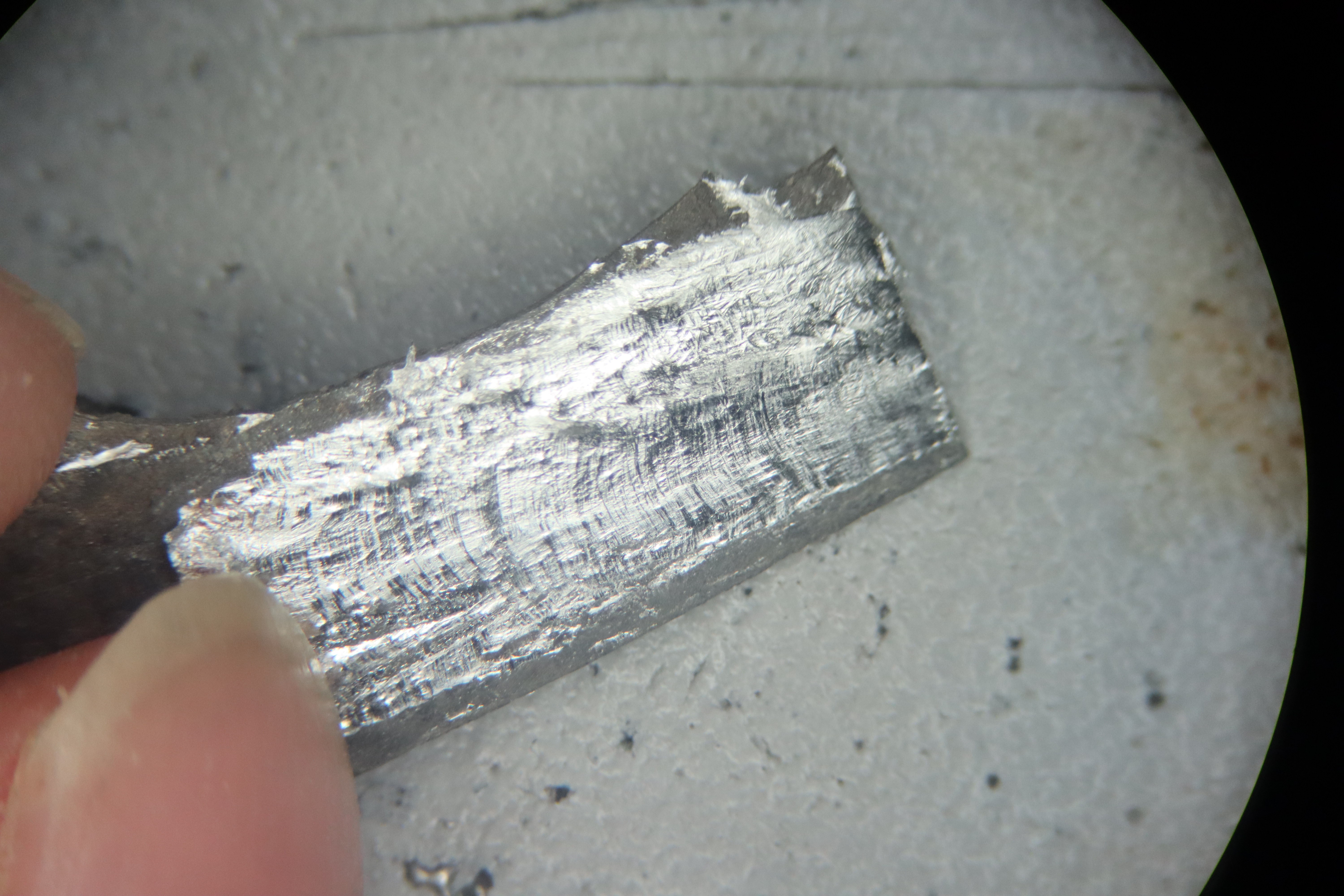
Luckily, I thought ahead and ordered a 1.75mm bondtech extruder last week, and it should be arriving shortly. That plus one more thorough cleaning and one more alloy reformulation should get me hopefully all the way to my first complete print with this technology. I do anticipate a bit more tuning of Prusa Slicer settings and maybe even some custom G-code before it prints perfectly though.![]()
Here's a nice microscope close-up of interlayer bonding on the first 5 layers on a piece I broke off. These layers were bonded together with roughly the same strength as the bulk material when tested with pliers after taking this picture. The deformation was ductile and it did not tend to fail across any of the interlayer structures. This demonstrates that this style of printing can print multilayer structures in principle, and now that we've identified all the major clogging mechanisms as well, and found solutions for all of them, no fundamental physics stands in the way of getting this system working: only engineering and perserverence is required from this point out. I see the light at the end of the tunnel.
-
Progress?
11/10/2021 at 21:48 • 0 comments![]()
Got slightly further before it jammed? I'll take it! It still jammed, and I'm pretty sure I know why: Prusa Slicer starts with the fan off for better adhesion between layers but I was using that same fan on the cold end of the extruder to keep that side from getting melty soo...
![]()
Things got a little too melty. Also It looks like the default fan on the E3D nozzle is 24v, so I'll get a 12v one with ideally more CFM to get more cooling power on the cold end. I'll probably do a full teardown and diagnosis while waiting for those parts, in case I can think of a way to get this running before those arrive. The default oozebane settings might be way too high, causing liquid metal to jump into the cold end, among a few other possible issues.
![]()
Really feeling this web comic right now...
-
Issue identified
11/04/2021 at 22:29 • 0 commentsDuring the last test the metal filament kinked and the extruder clogged. I initially thought it was just due to the bend in the wire, but while the system was hot, the wire could spin freely, although it wouldn't budge when pushed in or pulled out.
![]()
As soon as I noticed that the wire could spin freely I was pretty sure I knew what was going on, but I wanted to make sure, so I took apart the clogged extruder and sectioned the clogged cold end.
![]()
As I suspected, the nozzle and heatbreak performed just fine, wetting and not wetting where expected. The anodization on the aluminum heatsink also performed admirably: the interface between the feedstock alloy and the aluminum is very clear and there is no metalurgical bond between the aluminum and the tin-zinc alloy
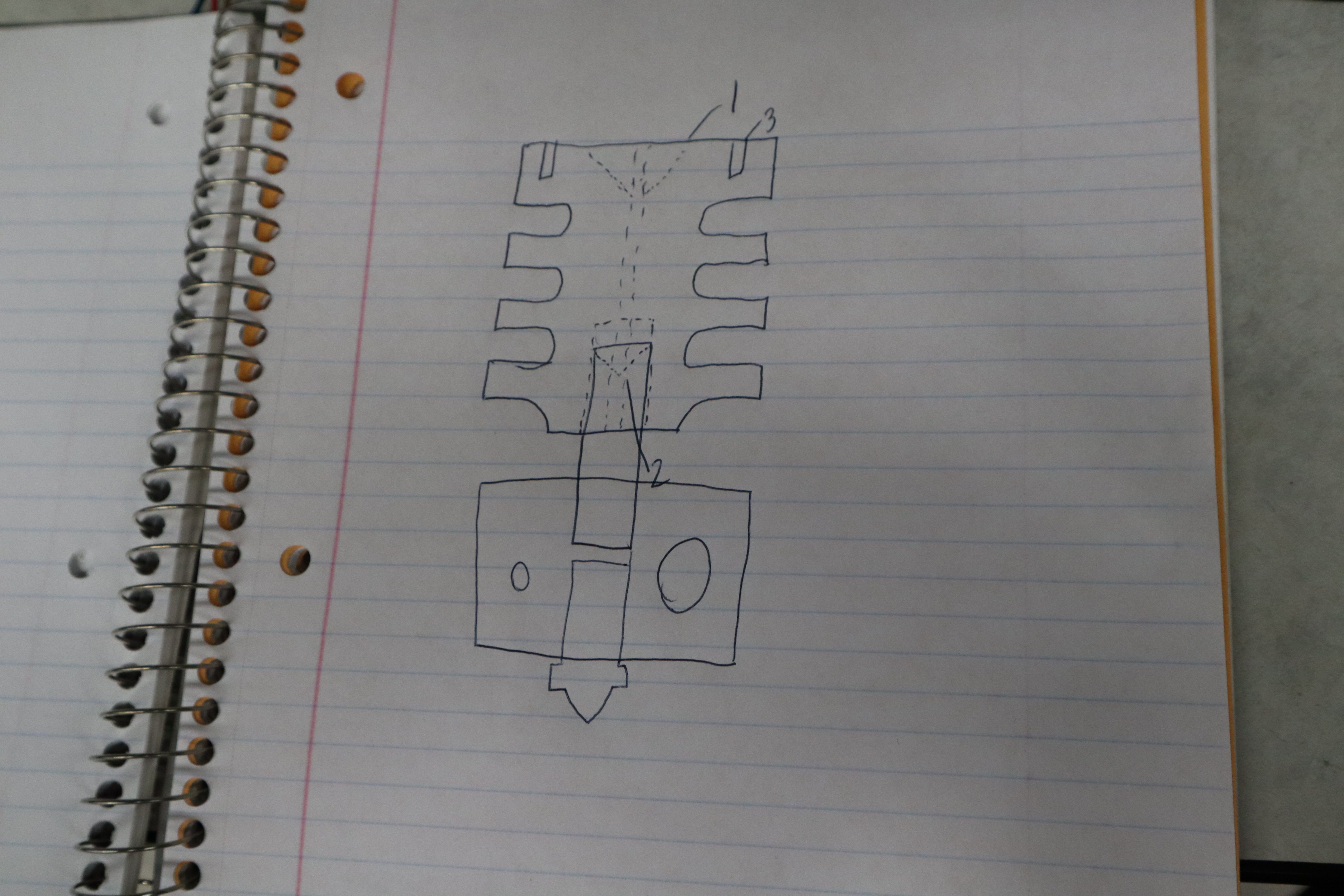
Thankfully, just as I suspected, this was an easy thing to fix. Some metal flowed back up towards the cold end and solidified in a cylindrical cavity behind the back of the heat break. Then, because it was in the cold end, it could not melt again and flow through the nozzle. Some thermoplastic extruders encountered the same issue during their development in the RepRap project. It will just require some 3D modeling on my part and maybe some waiting for a few more components in the mail, but implementing the fix for this will be nothing new. But for those who are not familiar, I'll explain:
![]()
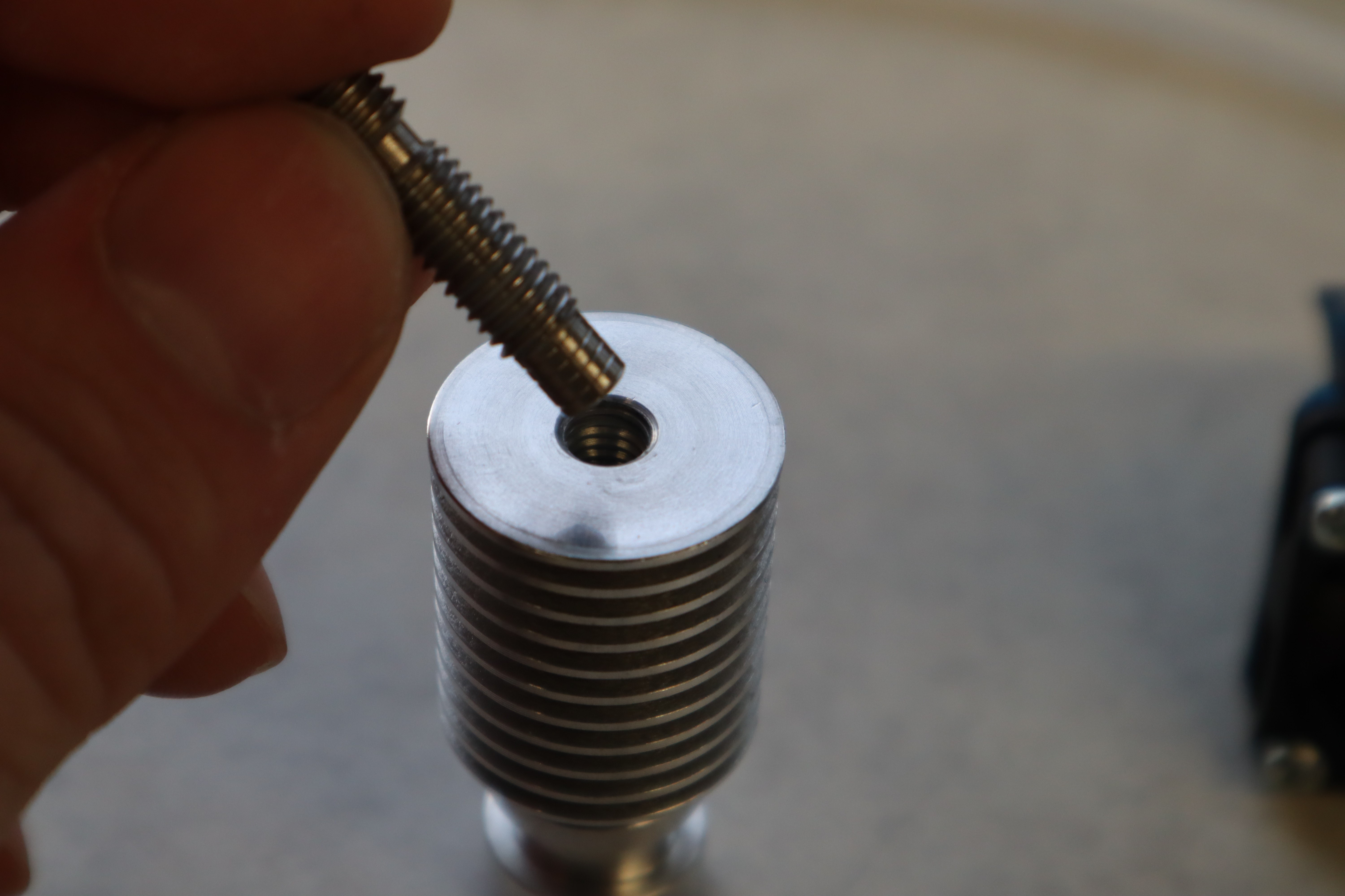
If you look at the heatbreak of most modern nozzles, they all have this extra unthreaded section in the cold end.
![]()
This design feature is key because when you want to tap threads into a hole that doesn't go all the way through the part, it's hard to get threads all the way to the back of the hole. Indeed as you can see above, the filled section doesn't really have threads. Bottoming taps can do a little better, but still aren't perfect. In practice, this means a fully threaded heatbreak can't thread all the way to the back of the hole, leaving a cylindrical cavity behind it. I thought my liquid glass would still be viscous enough to prevent metal from flowing back, but without a cooling fan on the heatsink, apparently the temperature gradient was not steep enough for that effect. Without active cooling, and with the cavity in a position where the feedstock alloy started getting melty, it's no surprise that this region quickly filled with liquid metal from further below, which subsequently froze and locked the wire in place.
![]()
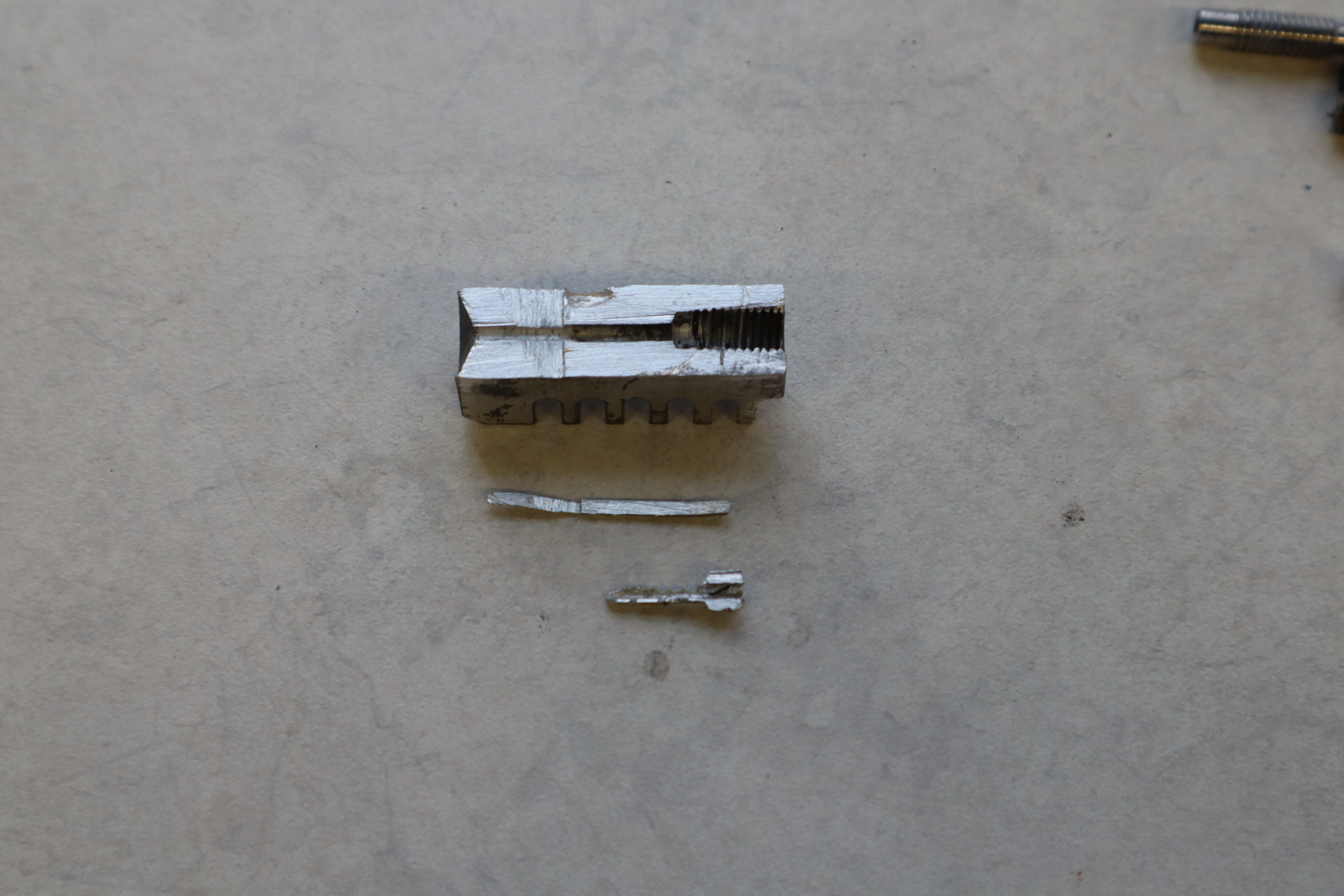
The unthreaded section of E3Ds heatbreaks is made to fill up the unthreaded or poorly threaded space at the bottom of the hole and prevent that area from filling up with plastic. It even has a lip at the back of it which bites into the aluminum to seal it well. This leaves no cavity where plastic or metal could potentially get stuck, reducing the possible failure modes of the hotend. So all I need to do is implement the same idea on my extruder. Since I've destroyed my heatsink to demonstrate the failure mode, I think I'll cannibalize the E3D extruder I have, or get one shipped quickly via Amazon, since this E3D nozzle was an old one meant for 3mm filament and I have 1.75mm metal filament instead. I would need to anodize the aluminum and black oxide coat the stainless steel depending on the grade, or if I get one of the new titanium heatbreaks then I would anodize that as well. I'll probably need to redesign and reprint most of the extruder system as well.
![]()
And just to show that feedstock alloy has not welded onto the aluminum, we can remove it with no damage to the surrounding aluminum. What's especially fascinating about this is that the solidified melt around the filament actually detached cleanly from the filament wire. This demonstrates that it backflowed from further down in the extruder then solidified further up where it was cold. Indeed, the small finger of metal that shot up really far into the cold end may have been the thing actually jamming the nozzle, because further down I would have expected the metal in the cavity to at least be semisolid, which shouldn't have impeded the movement of the wire, tending instead to deform out of the way. Whatever the case may be, it would probably be better if that cylindrical area were filled so that the tube is fully constrained, and it will be better to have a steeper temperature gradient by putting a fan on the heatsink: this will keep the liquid glass highly viscous, preventing metal from shooting up into the cold end as far as it did here. Those two adjustments should fix this issue, just as they previously fixed it for plastic printing. My bad for not remembering that detail, but I suppose it's certainly worth it to go through some more obscure 3D printing history/engineering most people probably aren't aware of. I also wonder if I can pinch off the metal flow if I add a metal drawing die or similar constraint that the wire just narrowly fits through, but I think that may prove more finicky than just increasing the glass gasket viscosity, especially when the bondtech teeth bite into the metal filament: it would make the seal inconsistent. I'll keep that option on the table for later perhaps; maybe a silicone O-ring could suffice at low temperatures.
![]()
the smooth surface demonstrates that this material did not wet onto the aluminum threads, and in the previous image, the threads in the aluminum are clear as far back as the threads go; this means that the anodized coating on the aluminum worked as intended, because normally tin-zinc loves to weld to and dissolve aluminum.
Anyways I've got my work cut out for me, but at least for once I'm not inventing something entirely new to get around a problem few people have ever encountered before, and I've got a solid roadmap in front of me. I think by the middle of the month, I should be back to printing stuff, without the part where the extruder clogs. -
The history of SMP and some shoutouts
11/02/2021 at 18:16 • 0 commentsThe first attempt at this type of printing was done by someone on the Lulzbot forum back in 2013. Back then they didn't give any particular consideration to the material properties of the molten metal, which is why they couldn't get past the clogging issues they were having.
Later on in 2013 or 2014, some high school student who's name I forget tried semisolid metal printing with an antimony alloy. Were they the one who eventually went on to start Vader Systems? I forget but if anyone still knows where that info is, please do mention it in the comments.
In 2015 I started a project at WPI which over the following years became a full scale collaboration with Lawrence Livermore National Lab and produced some papers. But the technology was abandoned: they attempted to print in the semisolid state, but semisolid metals undergo granular jamming under compression and shear, because they are not one homogenous phase. This meant that either the nozzle had to be very wide as with a concrete printer, or they had to implement something complicated to avoid granular jamming. Ultrasonic, induction and direct mechanical stirring were proposed, but each had its pitfalls, either making the system more expensive than other metal printing technologies, or outright not being feasible. I've heard whispers that Desktop Metal also attempted Semisolid Metal Printing, but evidently they got no further than LLNL.
While at Voxel8 in 2015 and again in 2016, I attempted to further develop semisolid metal printing in order to print traces for use in 3d printed circuit boards. This time, it was abandoned by a fluke more than any engineering bottleneck: the company pivoted to printing shoes, and therefore didn't need the capability to print metal anymore. I learned what I could from that last prototype, and continued thinking of a way to solve all of its flaws.
And so we find ourselves at today, with this project. I've iterated a few more times on my own, and we're finally closing in on a real engineering solution. It's been a long road.
Many thanks to Ninja-Robot for their affordable and customer-focused CNC machining service! Go get your stuff machined with himShoutout to Johnny at Ultimachine: I've never managed to brick a RAMBO dude, and I know a ton of that is thanks to your diligence.
-
Last couple bugs
11/02/2021 at 02:51 • 0 commentsI tried hard oxide coating the aluminum: unlike normal anodization, this process requires high voltage and active chilling, as well as a ramp-up in voltage that is gradual so that the surface isn't porous. Also, it evidently requires a fresh surface to start with:
![]()
I machined this feature on the top to retain the liquid glass gasket material and prevent it from getting stuck in the threaded holes. The hard oxide coating was somewhat microporous because I ramped up the current too fast, but on this freshly cut surface it was stable.
![]()
The rest of the surface was already anodized, so I assumed nothing would happen there. I guess it got scraped over time from handling. It also seems like fingerprints somehow destabilized the alumina coating under additional anodizing. Doesn't look pretty; oh well. The thick oxide coating was still very protective and abrasion resistant. The dark areas are hard oxide coated, and rose off the surface kind of like braille: the oxide coating got surprisingly thick!.
![]()
Setting up the liquid glass gasket was a little finicky with this design. I'll have to figure out something better in future iterations. First we prime the metal wire with some melted borax/glycerol (50/50 wt %) that has been cooked at 220C for 1 hour to fully diffuse the components into each other. This solidifies on the wire in a film as it cools, almost like molten sugar.![]()
I then heat up the hot end and squish it in through the top.
![]()
I may have added a bit too much borax/glycerol mix.
![]()
To correct somewhat for the overheating in my previous test, I added wooden belt clamps and tacked on an infrared reflector on the bottom of my extruder cold end to help keep it cooler. It was just some extra graphite gasket I had lying around. It wasn't perfect, but it worked well enough for now, because I was finally ready for my first true test print. After a false start with some bad slicer settings, here's the result of my first attempt:
![]()
The high temperature heat bed worked perfectly: it kept the metal molten long enough to wet to the print bed (Print beds at the normal temperature of around 60C are nowhere near hot enough in my experience). But then almost immediately, the extruder jammed! It's always something, isn't it? The issue was easy enough to diagnose:
![]()
The wire had buckled in my crappy prototype extruder because it wasn't constrained properly. And moreover, when I opened up the nozzle, the molten metal had forced its way up into a cavity in the cold end and solidified, locking the filament in place. It will spin around because the cavity is circularly symmetric, but it won't push in or pull out. This means I need a steeper temperature gradient and more careful control of the internal geometry of the extruder. Luckily, I have an extra E3D nozzle I can cannibalize to test that out. More info will be available as soon as that's done.
Also something important to note: If you look at the Prusa Slicer config, you will notice that the print temperature is set to 300C instead of 240: this is because of the thermal gradient from the nozzle to the print bed: while printing, we want the very tip of the nozzle to be at about 240C, so to achieve that in practice, we need to increase our print bed temperature substantially, and need to do the same with the hotend. For the extruder geometry I chose, a midpoint rule can conveniently be used to roughly estimate the extruder and bed temperatures required: the extruder set point is 60 degrees above 240, and the bed temperature is 70 degrees below that temperature. A bed temperature of 180 degrees would work just as well. for an even split. All that temperature gradient falls across just the small nozzle, so it's feasible to control the temperature gradient precisely with a large heat source and sink: the heater block and the print bed. In that sense, the thermal boundary conditions are controlled.
-
Quick update before the Hackaday Prize deadline
10/27/2021 at 03:11 • 0 commentsI wanted to post a video of my printer actually printing tonight, but I ran into a couple unexpected bottlenecks. First off, my Y-axis belt clamps straight up melted off!
![]()
I guess I should have expected something like that now that I can heat the print bed up to 200C. No biggie: I can make new belt clamps out of laser cut wood and epoxy that will hold up to the forces and temperatures.
And secondly, there were 3 issues I need to fix with the extruder.
![]()
- There needs to be a liquid glass gasket reservoir on the top to enable easy application of the gasket material, and so that it will pour into the extruder after being applied. Otherwise it is quite difficult to actually apply the gasket material
- The heat break I used was filled in with molten solder to keep the inner wall wettable by the feedstock alloy, but the heatsink worked too well and cooled the upper end of the heat break until the solder there was always solid, all the way up to 300C measured in the heater block. Moreover the drill through-hole wasn't perfectly straight because the old drill press I used wasn't great, so the metal filament wasn't even hitting the hole in the heat break. This can be fixed by a bunch more dremeling, anodizing, black oxide coating and other processes I'll explain in more detail once I have pictures to show of them.
- The kinematic coupling to the extruder seemed loose when the extruder was heated up to temperature: this means that the plastic components were heating up too much. In the future I can fix this with a better heatsink geometry, but for now I can laser cut some wood parts to replace more of the plastic.
On the bright side, the design does not leak or form gas pockets, unlike old designs from the past. This means as long as the gasket forms a good seal, it will be capable of controllable extrusion. These problems may take a day or two to fix, but after that we'll be all set to print!
On an unrelated note, when reviewing my documentation I noticed I hadn't talked about my print bed modifications yet!
![]()
They're quite straightforward and I'm not entirely certain they are necessary to get Semisolid Metal Printing functionality, but they've been very helpful in prototyping things so far, and I'm sure they can help other people with other projects down the line I'll add 3D models at some point but mine are hand-machined because it was easy to do with a dremel and a drill press. It's just a 1/4 inch by 8 inch square 6061 aluminum plate, some drilled plywood, a 200X200mm E3D high temperature heat bed (requires a beefy solid state relay and some wire), some 0.2 inch by 3/8 inch SmCo magnets, a .042 X 8 X 12 inch spring steel sheet, and a little epoxy. I just drilled out holes slightly larger than the SmCo magnets and epoxied them in, then drilled holes as needed in the plywood (The Prusa Mendel I2 Mk2 documentation includes a printable drill guide/laser cutting DXF)) and drilled then dremeled the corners of the aluminum plate so that the bolts would fit sunk into the surface. I also added some thermal compound between the heated bed and the aluminum to help conduct the heat from the bed into the aluminum. -
A brief aside on conversion coatings
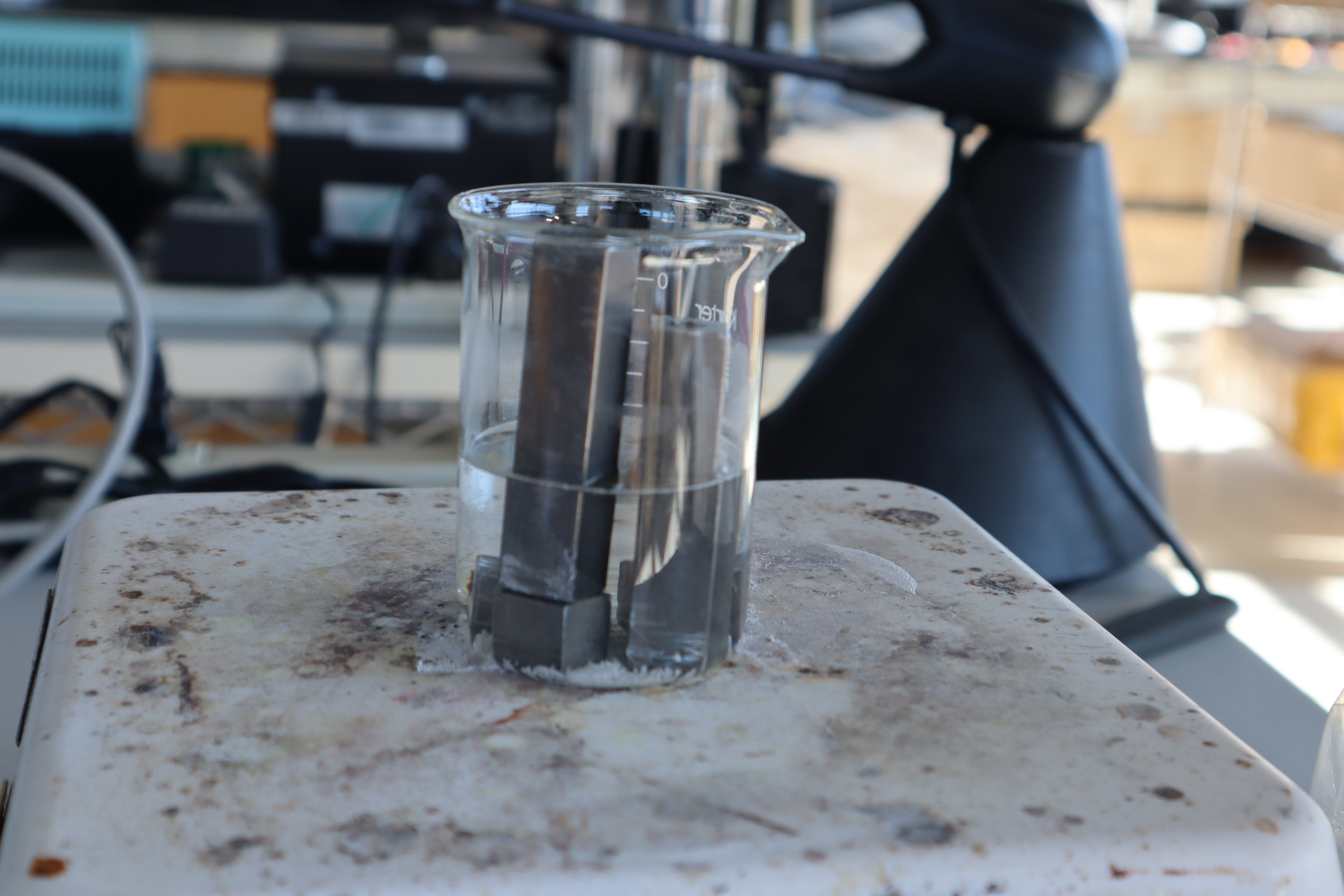
10/22/2021 at 14:54 • 2 commentsOne of the key details for semisolid metal 3D printing technology is controlling and patterning wettability to passively control the flow of the liquid metal, and mitigating solubility of the nozzle in the molten metal. With steel and aluminum alloys, the easiest way to do this is with black oxide coating and anodization respectively. Over the past few weeks I have run many experiments to implement these in my process. In my first experiment I learned that black oxide coating of steel doesn't really happen much in the absence of nitrates and nitrites.
![]()
With my first test in sodium hydroxide using mild steel, I got the following result:
![]()
There is a thin dark layer of presumably magnetite nanoparticles in the dipped section after running for an hour at the recommended 140C, but it's barely distinguishable and definitely not thick enough to resist abrasion. Moreover, partially submerging the parts led to rust at the air-liquid interface, where the solution didn't limit oxygen diffusion and control the surface chemistry of the iron It may also be that the iron exposed to salt and air galvanically protected the region below the fluid from forming magnetite at a faster rate. I was hoping for a cleaner interface; perhaps there is an electroplating process that can do that. Worst case scenario I could black oxide coat the whole part, then machine away the coating where it isn't needed. Later on I thought of another solution described further below, which works well for my purposes.
![]()
So then began a series of additional tests with anodization, and in the process I discovered that TSP-borax electrolytes are perfect for anodizing titanium, in case that becomes useful later on. The electrochemical attempt at black oxide coating steel shown above ended in relative failure: the oxide coating was nice and dark, but did not withstand much abrasion and wasn't electrically insulating or corrosion resistant. In the end I opted for standard hot tank bluing with a solution of 2 parts sodium hydroxide, one part sodium nitrate by weight, and just enough water to get it mostly dissolved at 140C. Running that process for about an hour ended up with a workable result, but in the future I may need to optimize further.
For anodizing, I just followed this guy's instructions for aluminum anodizing here and it worked like a charm. I think I used 12 grams of 70% sulphuric acid per 1000 grams of distilled water, so it was a little bit overly concentrated compared to what other people use. I didn't even wire brush or sand blast the parts ahead of time, they just had their typical machined surface finish, and the surface finish at the end reminded me of a Macbook Pro's surface finish, with the machining marks hardly noticeable.:
![]()
That said, I'd like to go even further in the future and try hard oxide coating, where you chill the sulfuric acid bath to near freezing then dump many amps through it at 100 volts or more. Hard oxide coatings on aluminum and titanium can be extremely abrasion and corrosion resistant.
I realized that my printing alloy melted around 240C, well above the temperatures required for black oxide coating steel. To selectively keep surfaces wettable, I filled or covered those regions with my printing alloy as a mask. Like these drilled vias in these components about to be black oxide coated.
![]() An M2 tool steel extruder with a rough attempt at patterned wetting properties at the tip. M2 tool steel offers excellent wettability but low solubility in molten zinc alloys, so it makes for an excellent nozzle for this kind of printing. All the threads required anodization or black oxide coating because, as I have learned, you do NOT want to encourage the molten metal to wick into the threads and squeeze out via capillary action. That happened to me once at a previous company: once the liquid metal wicks in and wets the threads, it's virtually impossible to stop and you generally have to throw away the whole component and make a new one, or abrade away all the related surfaces and hope you have a usable part at the end of that.
An M2 tool steel extruder with a rough attempt at patterned wetting properties at the tip. M2 tool steel offers excellent wettability but low solubility in molten zinc alloys, so it makes for an excellent nozzle for this kind of printing. All the threads required anodization or black oxide coating because, as I have learned, you do NOT want to encourage the molten metal to wick into the threads and squeeze out via capillary action. That happened to me once at a previous company: once the liquid metal wicks in and wets the threads, it's virtually impossible to stop and you generally have to throw away the whole component and make a new one, or abrade away all the related surfaces and hope you have a usable part at the end of that.![]()
Here are the finished black oxide coated and anodized components, ready for use in the extruder. Thanks to NinjaRobot for machining these for me!
![]()
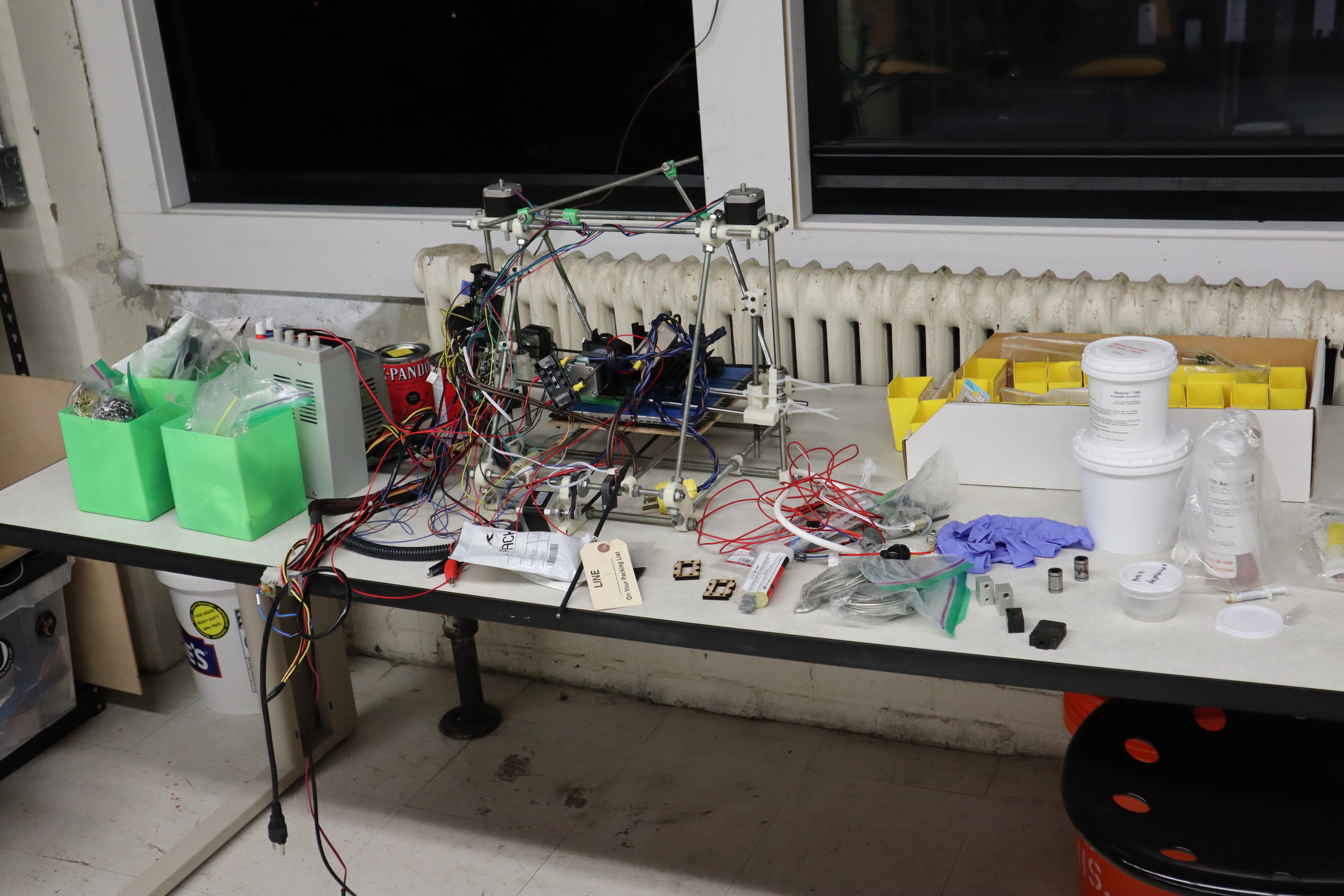
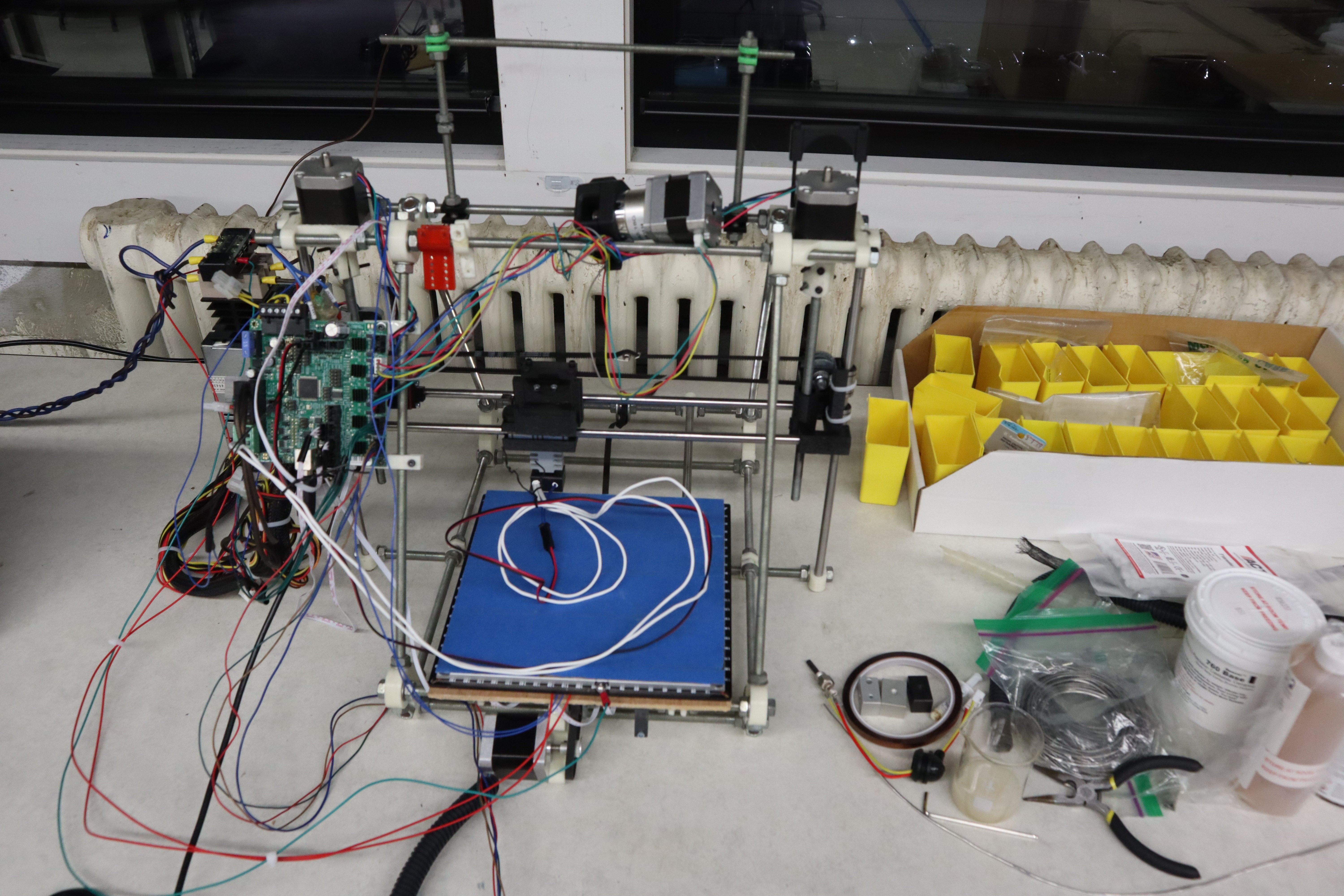
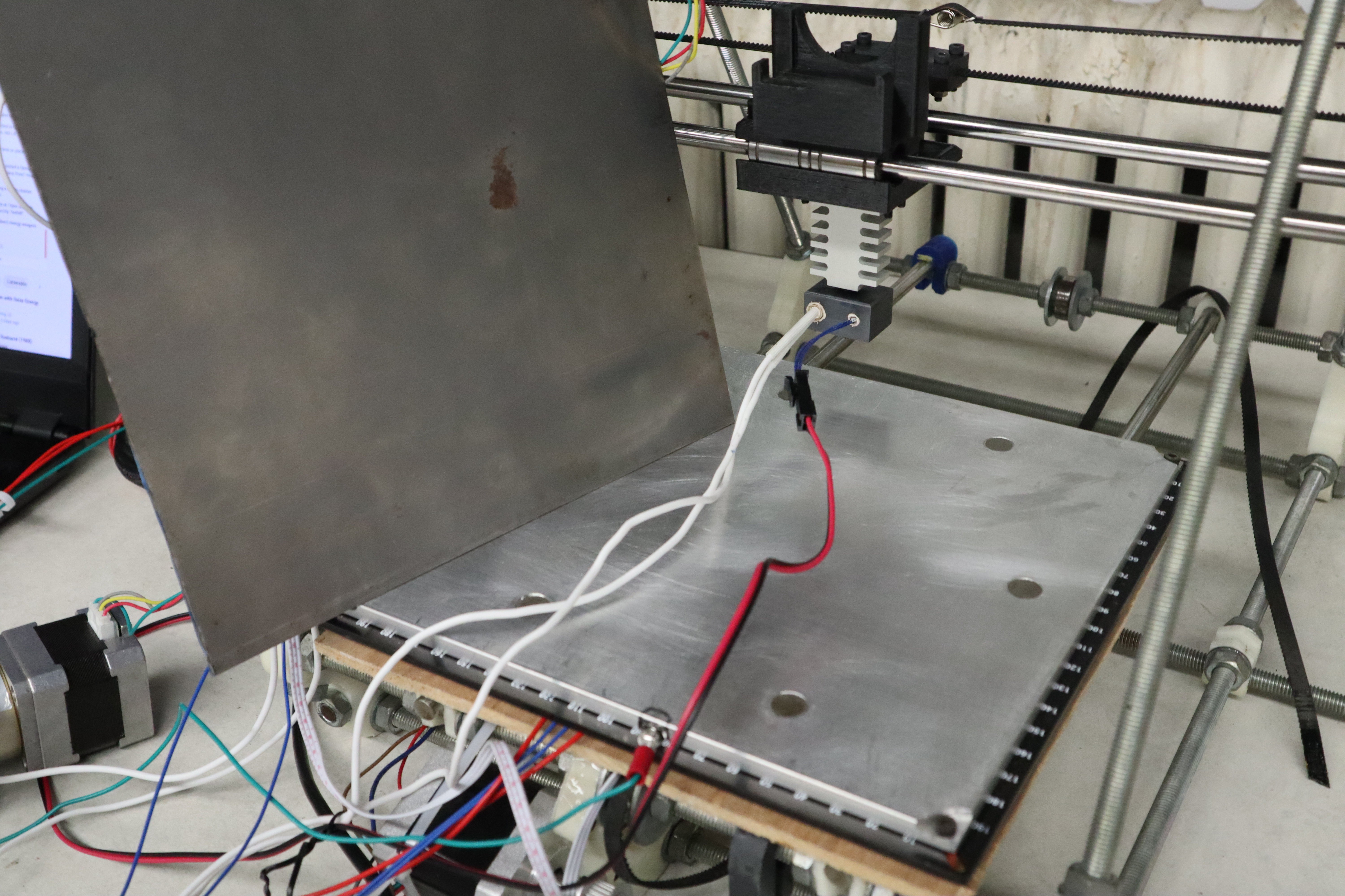
Finally, with those done, it was time to assemble my new extruder for molten metal, and get it on a working printer! Womp womp... I haven't touched my old Prusa in at least 5 years and it needed some TLC.
![]()
After much effort, barring a bit more wire management, my printer is just about ready to go! Metal printing experiments start today
![]()
On a somewhat unrelated note I broke a drill bit in one of the components I had hoped to black oxide coat. Luckily, diamond tipped bits are poor man's electric discharge machining if applied very carefully: break one of these in there though and you're just done. Once you've embedded diamonds in there, there's not really a good way to recover.
![]()


 An M2 tool steel extruder with a rough attempt at patterned wetting properties at the tip. M2 tool steel offers excellent wettability but low solubility in molten zinc alloys, so it makes for an excellent nozzle for this kind of printing. All the threads required anodization or black oxide coating because, as I have learned, you do NOT want to encourage the molten metal to wick into the threads and squeeze out via capillary action. That happened to me once at a previous company: once the liquid metal wicks in and wets the threads, it's virtually impossible to stop and you generally have to throw away the whole component and make a new one, or abrade away all the related surfaces and hope you have a usable part at the end of that.