Michael Perrone
-
Quick update: the new design
09/26/2021 at 13:55 • 0 commentsWhile hiking up Mt Ranier I kept thinking about how I should redesign my metal extruder, and eventually near Camp Muir I arrived at a solution.
Printing metal filament is nothing like printing plastic filament: plastic is a viscous liquid which forms its own sealing surface as it passes through its glass transition temperature. Metal may have semisolid states where there are solid and liquid phases are mixed together, but it is possible to separate these phases, causing granular jamming and clogging nozzles. This can be avoided by printing above the liquidus, having material only pass into the semisolid state as it goes over a deposition brush.
If one attempts to print metal in a fully liquid state, the thin liquid will leak out of any hole provided: the metal does not go through a glass transition, and therefore it does not form a sealing gasket surface. It is possible to have extremely tight tolerances on the metal filament and on the extruder, but then any variation in your filament would induce a clog in the nozzle. The required precision would make metal filament far too expensive for the average maker. Rubber gasketing could in theory take the place of the self-forming sealing surface on the metal, but it would be limited to low temperatures and the trapped air would tend to expand when heated, causing the nozzle to drip.
This is how I arrived at using a liquid glass gasket: design low melting-point glasses which surround the metal wire as it enters the hotend and before it itself melts, to restore the gasketing behavior that thermoplastic normally has. Serendipitously, I discovered a few such compositions myself long ago when playing around with a hotplate, and a quick look through google scholar shows plenty of options for these low-melting glasses even below 400C. The vast majority of these glasses are less dense than the metal alloys I plan to work with, except maybe in the case of aluminum, where care must be taken to pick the proper glass. This is important because the liquid glass gasket remains in place due to buoyancy on the molten metal in the nozzle and a few other factors, and the molten metal remains in place because of the capillary forces in the brush, as I learned all too well when playing around with the MHD system. I'm getting some key parts to test this concept with machined at the moment, but it won't be long before this method gets tested. -
Rethinking designs
09/23/2021 at 21:52 • 0 commentsHi everyone! Here's how things have been going since the last project update:
![]()
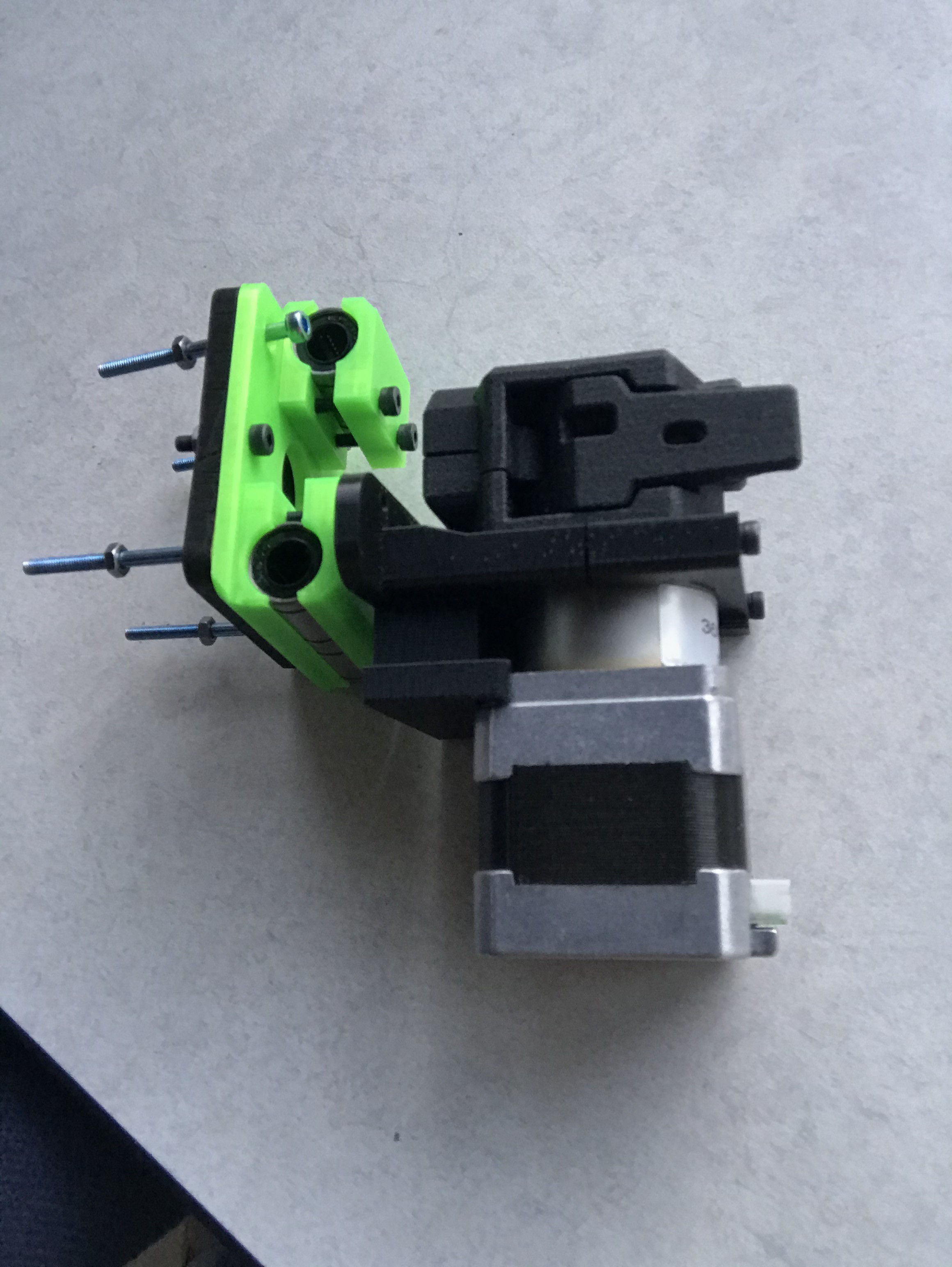
Firstly, I finished up the cold end of the extruder for attaching the MHD extrusion system to a bondtech extrusion system and my old Prusa Mendel printer, for prototyping purposes. (little did I know this effort would prove useless) Then I got back to testing my MHD extrusion system:
![]()
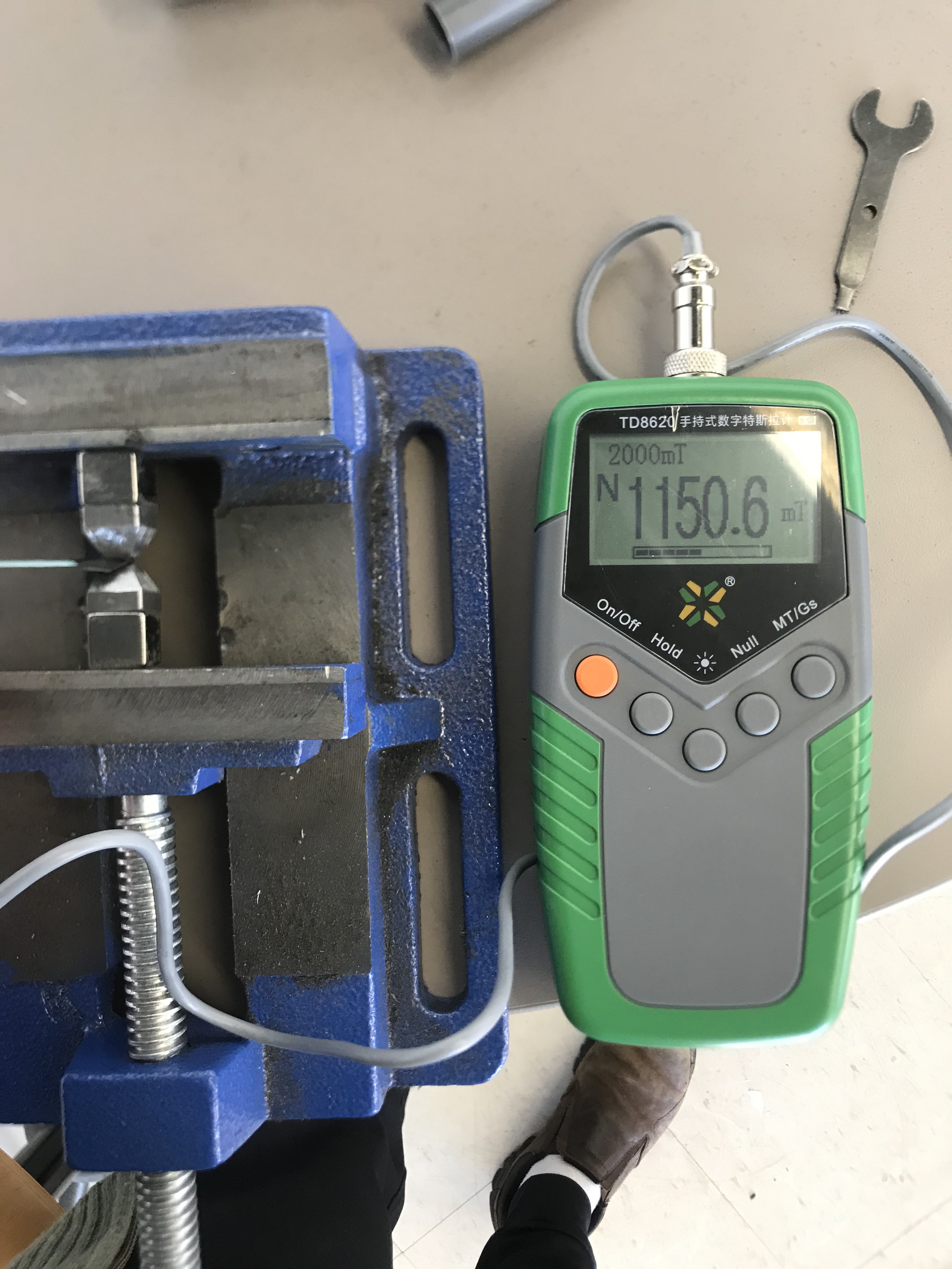
In the previous update, I had this extruder built as well, but there was a problem: the capillary force/surface tension of the liquid metal was just too high to be overcome by the MHD forces plus gravity. Even if it were enough, liquid metals are so thin that if it overcame the capillary forces, metal would shoot out of the tip very fast. This would require some very involved control electronics to stabilize, pushing the price well outside the range I was hoping for. I did a few tests with different magnetic yoke configurations and was able to get steady-state fields as high as 1.15 Tesla, but ultimately the chip shortage going on right now was the straw that broke the camel's back for this design, and I had to rethink things. The controls problem was workable if I could boost the field or the current enough, but if the control electronics were going to be prohibitively expensive or outright unavailable, it would defeat the purpose of making highly available metal printing at a cost makers can actually afford.
![]()
![]()
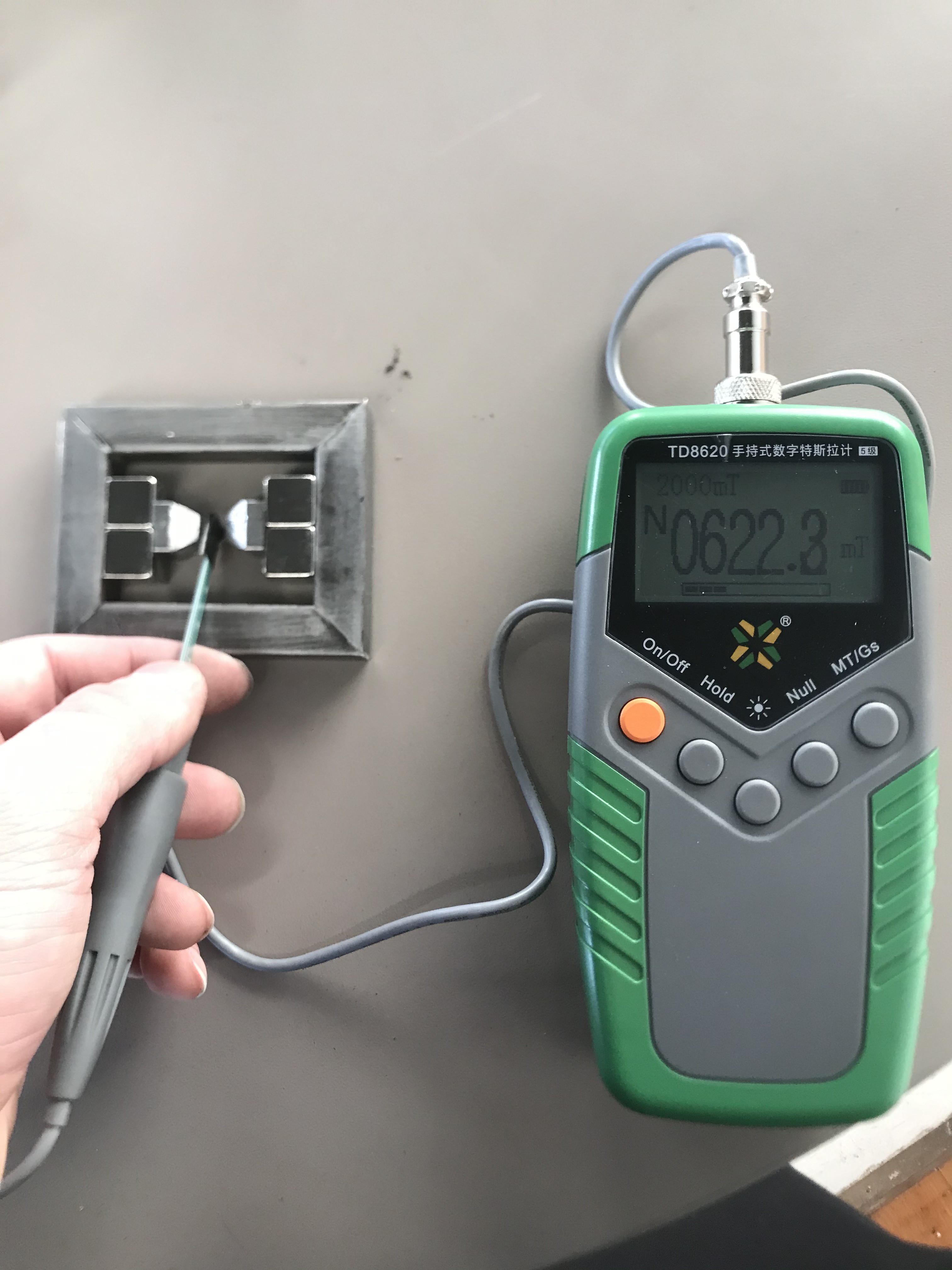
Here were some of the other test configurations to see how much magnetic field I could get out of the yoke. Perhaps having small volumes of high magnetic field will help someone else down the line, but I ultimately couldn't enhance the field enough for MHD to make sense for metal extrusion. I could have made up the difference than upping the current on the driving circuitry, but it was already going to be way too expensive, if available at all, due to the chip shortage. These digital tesla meters from China are pretty good by the way.
![]()
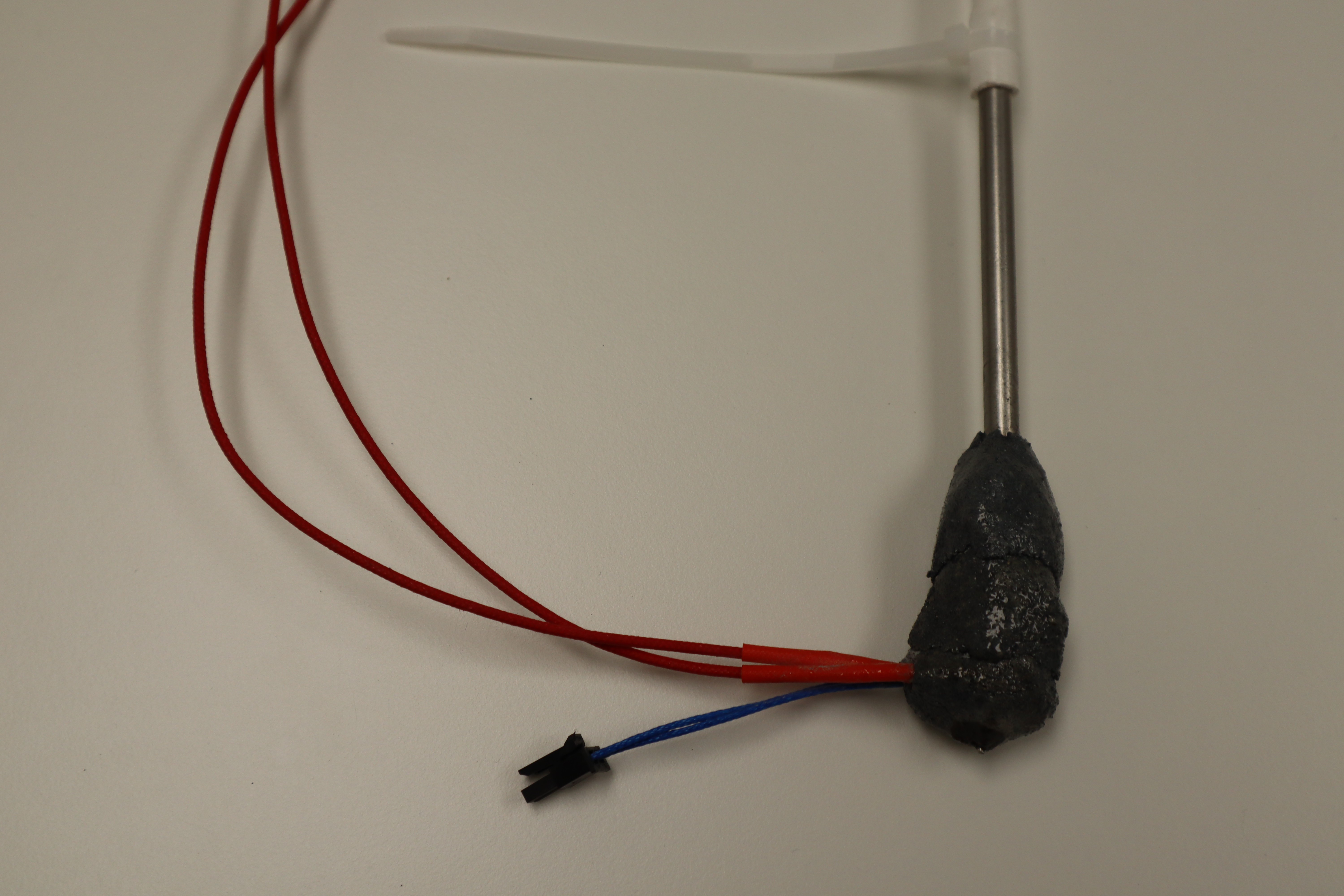
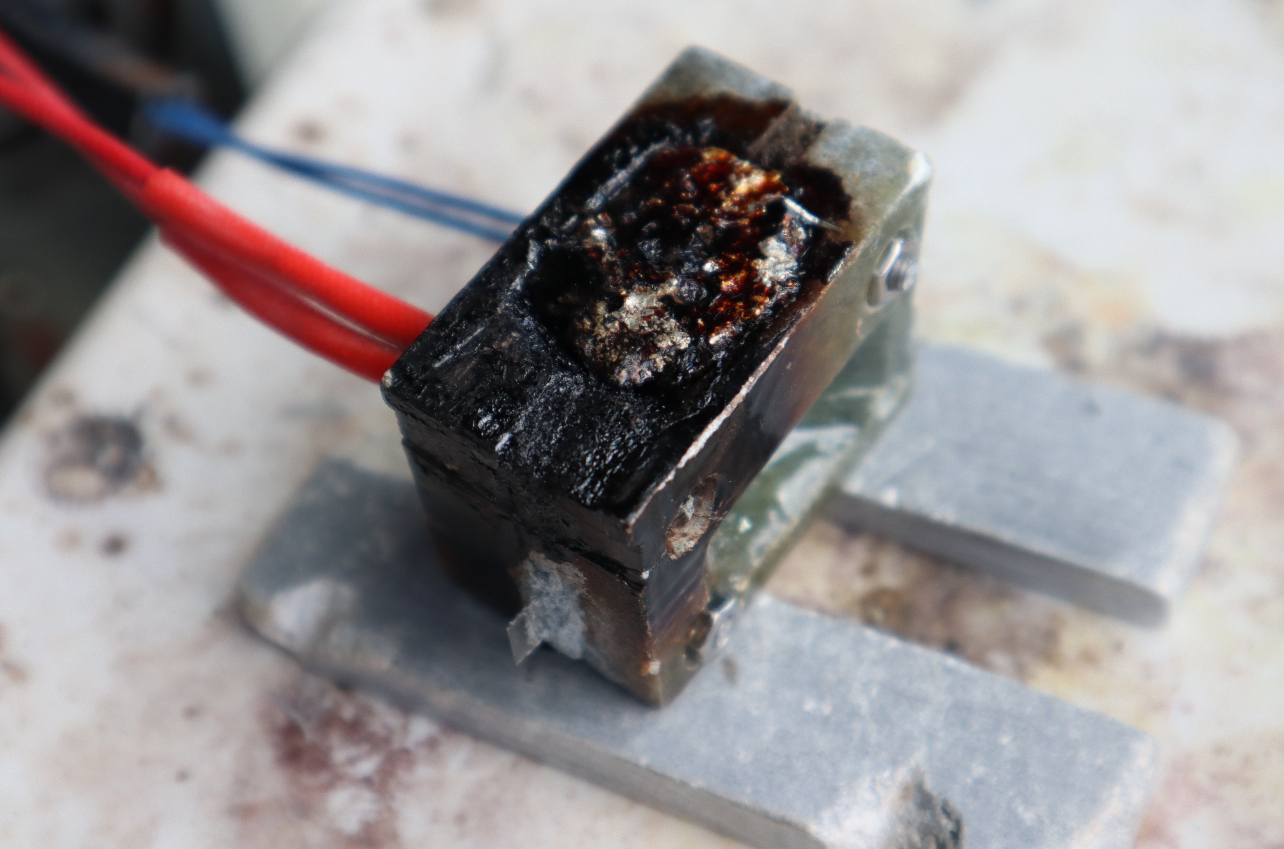
Since I couldn't get enough extrusion force with MHD, I threw together a new "nozzle" out of Cotronics Silicon carbide ceramic, plus high temperature epoxy for added tensile strength, in order to test pressure-based extrusion. With a stainless steel tube as a standoff for the tubing, I attached it to an air tank, pressure regulator, and foot pedal switch to open and close the pressure source. With this I was able to slowly increase the pressure to directly measure how much more pressure I needed, compared to how much the MHD system produced. The ceramic/epoxy held up surprisingly well to the pressure, without any leaks during testing at temperature. The secret was epoxying the stainless steel tube at the top: this allowed the different thermal expansion coefficients to just stress the high temperature epoxy, which had enough elasticity to it, and not the silicon carbide cemented ceramic. The extrusion pressure was about 4 times higher than what the MHD system could produce, which was in agreement with my calculations. Once capillary forces were overcome though, extrusion was not very controllable. I was able to stack material moving the thing around by hand as with a hot glue gun, but this print wasn't going to win any prizes.
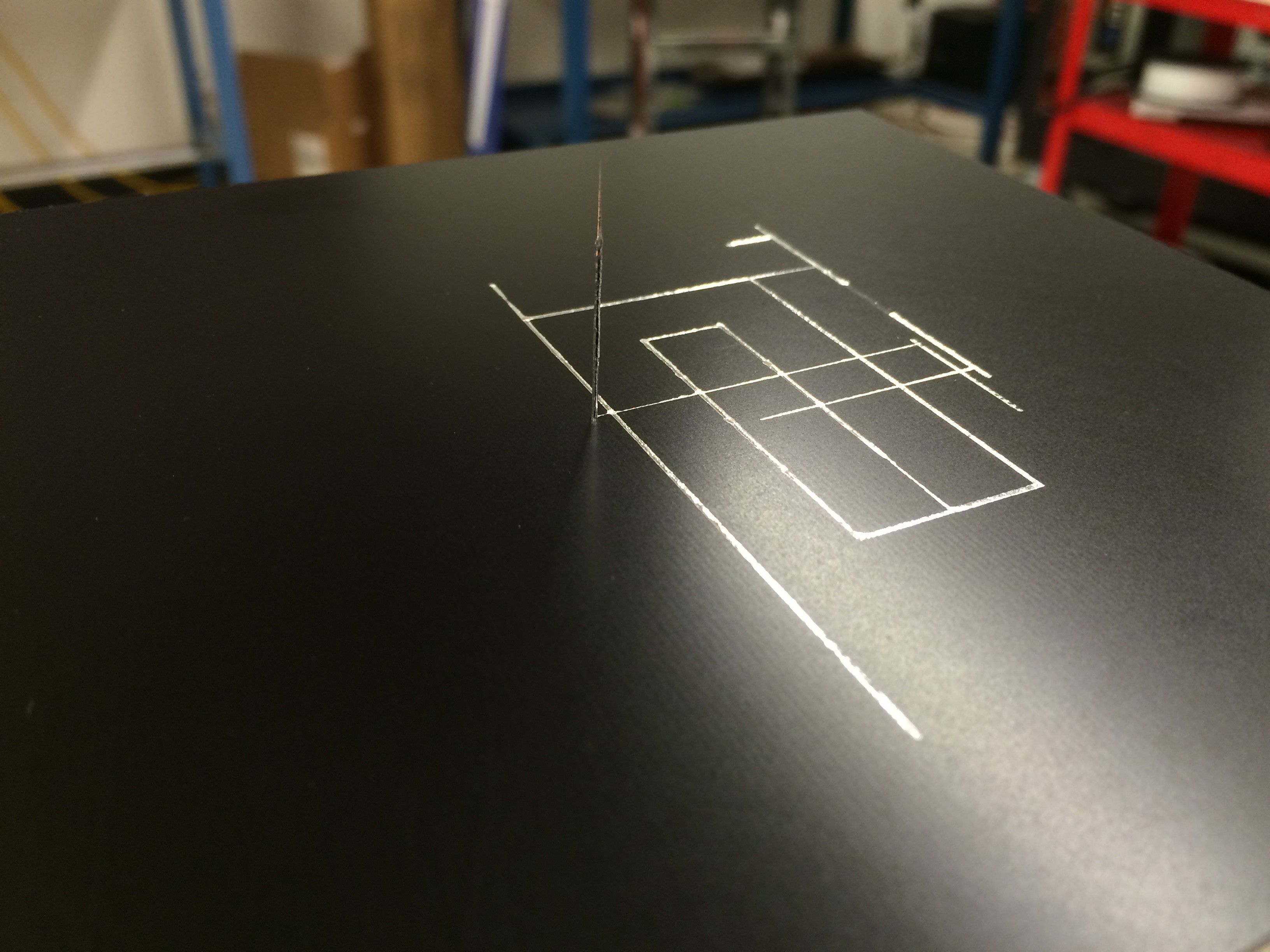
![]()
Even so, this was a key step forward relative to my previous work at Voxel8: we were able to make nice first-layer traces and bridge wires for long distances, but we couldn't build subsequent layers on top of previous layers because not enough pressure could be built up to keep the liquid flowing.
![]()
Extruding wire to demonstrate bridging capabilities with the the old system at Voxel8 in 2016. The capillary properties help extrusion stability in this case instead of acting against it, making extrusion control easier.
![]()
The same thing was true for producing traces with the Voxel8 machine: the substrate was stable enough; even printed substrate performed decently. It was perfect for printing electronic traces to replace the silver ink we were using previously, but producing solid metal objects proved challenging, because while capillary forces would normally pull the material onto the substrate, instabilities added up when there was insufficient extrusion force while applying subsequent layers. This was in part because each layer melted into the previous, providing unstable boundary conditions for the capillary flow onto the substrate. If we had sped things up significantly, maybe it would have been possible to deposit each layer without fully melting the layer below, but then we would have required even more extrusion pressure, which was still a challenge with such a thin fluid. If I try pressure-based extrusion again I'll attempt it with a scroll compressor directly on the liquid metal instead: that might just engage the liquid metal enough to reach higher pressures in a controllable way.
Then again, with such a thin fluid, regardless of whether I use pneumatic pressure or MHD, operating in the pressure domain with such a thin fluid would require a very solid controls solution, both on the electronics side and on the software side. I found that again, that would put these extruder systems outside the price range I'm aiming for, if the aim is metal printing for makers. And that's not even considering the issues pneumatic systems have when interfacing with hot things like molten metal: gasses like to expand under those circumstances, causing steady dripping. Therefore, knowing the extrusion force I needed to be able to hit, I began looking for a viable volumetric extrusion method, as opposed to a pressure-based method.
Printing from above the liquidus temperature of the alloy prevents nozzle clogging by granular jamming, which ultimately stumped Lawrence Livermore and Desktop Metal. But then your problem is that the liquid metal is just too thin. Plastics form their own gasket/plunger as they go through their glass transition, and as they are pushed through a hotend. This is why filament extrusion works with plastics. If you try this same thing with metals, the molten metal will squeeze up around the sides of the filament until it gets high enough to re-solidify, clogging the hotend that way, or at the very least leaking out of every available hole. For the longest time I was stuck, so I took a break to hike Mt. Ranier, and suddenly up around 9000 feet I realized what I could do to restore thermoplastic-like behavior, using what I now new about capillary pressure.
![]()
The solution I came up with was drastically simpler than the previous designs, and finally hits the price point I was aiming for. I'll go into more detail about how this new system can be used to extrude volumetrically despite the fluid properties of molten metal in my next post, coming this weekend. I'll be testing this design shortly to see if it will work.
-
Getting Started
06/26/2021 at 15:57 • 0 commentsNow that I've described how Semisolid Metal Printing can be achieved, here's the progress so far in reducing it to practice:
Firstly, making one’s own filament is surprisingly easier than I expected: equipment exists on the market for jewelers to melt metal and draw it into wire for a couple hundred dollars. These already quite refined technologies, with not much optimization or modification, could become something similar to the filastruder, but for metal. Due to wire drawing technology it would be even easier than with plastics to make wire with a very consistent diameters, because the final forming stage happens completely in the solid state instead of in a molten state. I should mention though that while wire feed is convenient, it might not be necessary if you have other ways to control extrusion (in my case capillary pressure equilibration plus magnetohydrodynamic motors). For example, it would be extremely inexpensive to meter in metal shot at regular intervals with a device similar to a gumball machine.
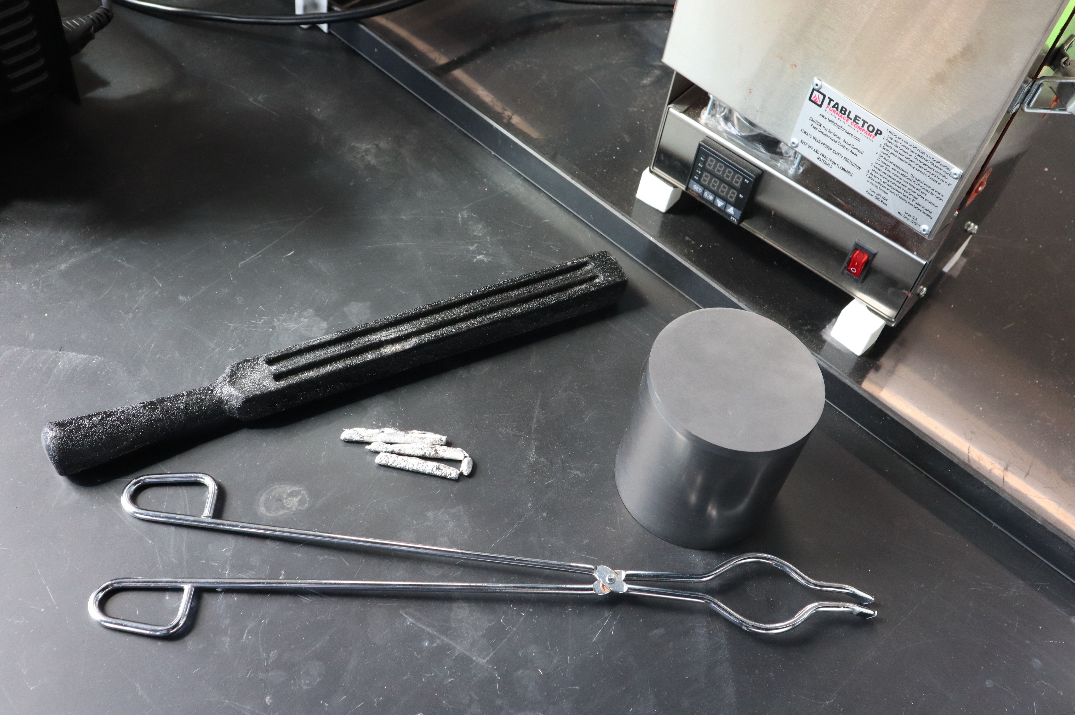
![]()
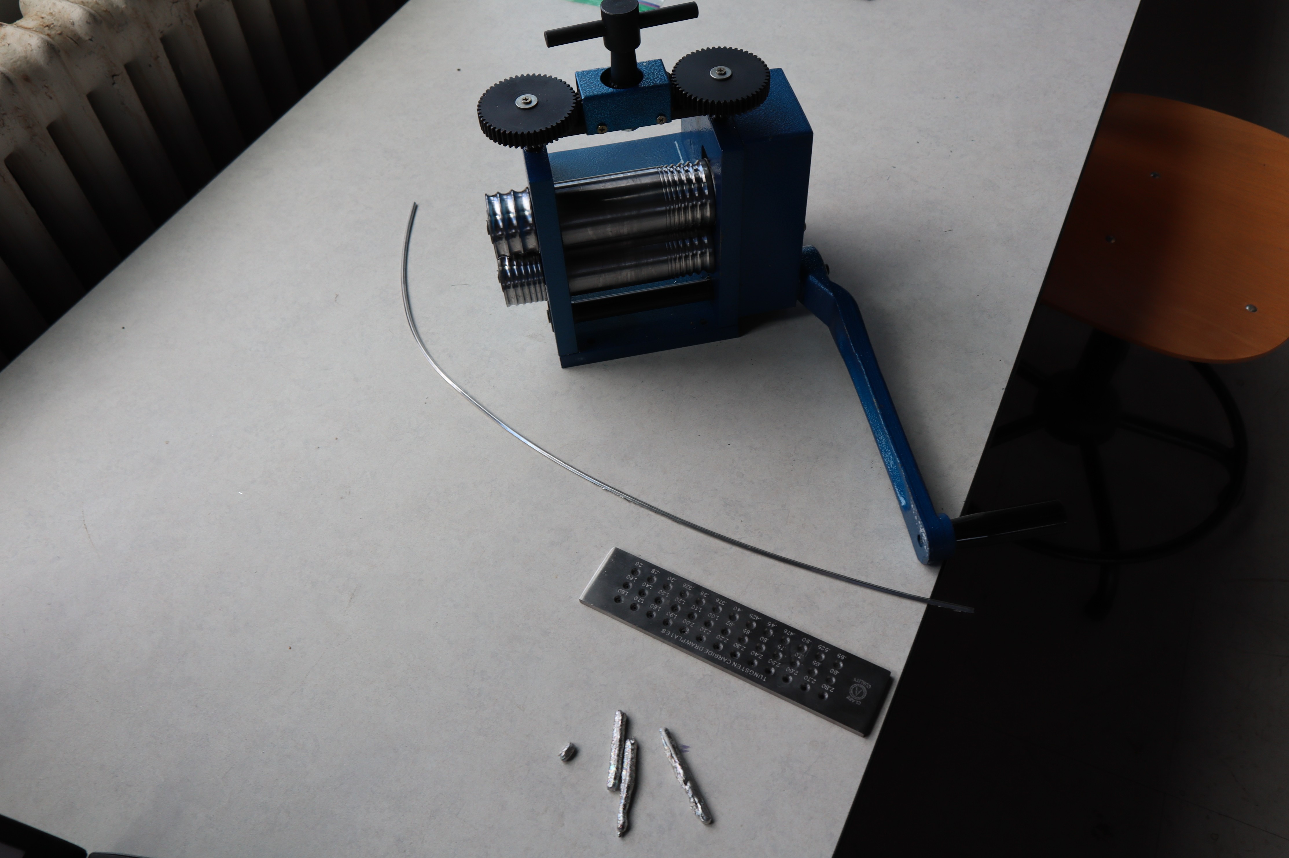
Tabletop Furnaces makes muffle furnaces well suited to preparing molten metal to draw wire from. They cost roughly $500 and if carefully handled, they can last a long time I can melt alloys from scratch this way at reasonably high temperatures, but if you have pre-made alloy shot or ingots, ~$25 metal melting pots for making lead shot are common online. Crucibles, tongs and casting molds can be used to cast long bars which can be subsequently drawn into wire. For large scale production, continuous casting seems to be the standard technology.
![]()
Here we have some prototype metal alloys in various stages of being drawn into wire, as well as a wire drawing plate and a rolling mill. At the small scale, wire drawing plates or wire drawing dies are standard for finishing wire for jewelry making, and miniature wire rolling mills can press the cast long ingots into wire thin enough to use in the drawing plate. Because of the jewelry industry, these technologies have existed for a very long time, and these are likely the easiest technologies to adapt to making filament for metal printing as a continuous process. Really the bottleneck will be the casting procedure, which for jewelry making, is not a continuous process.
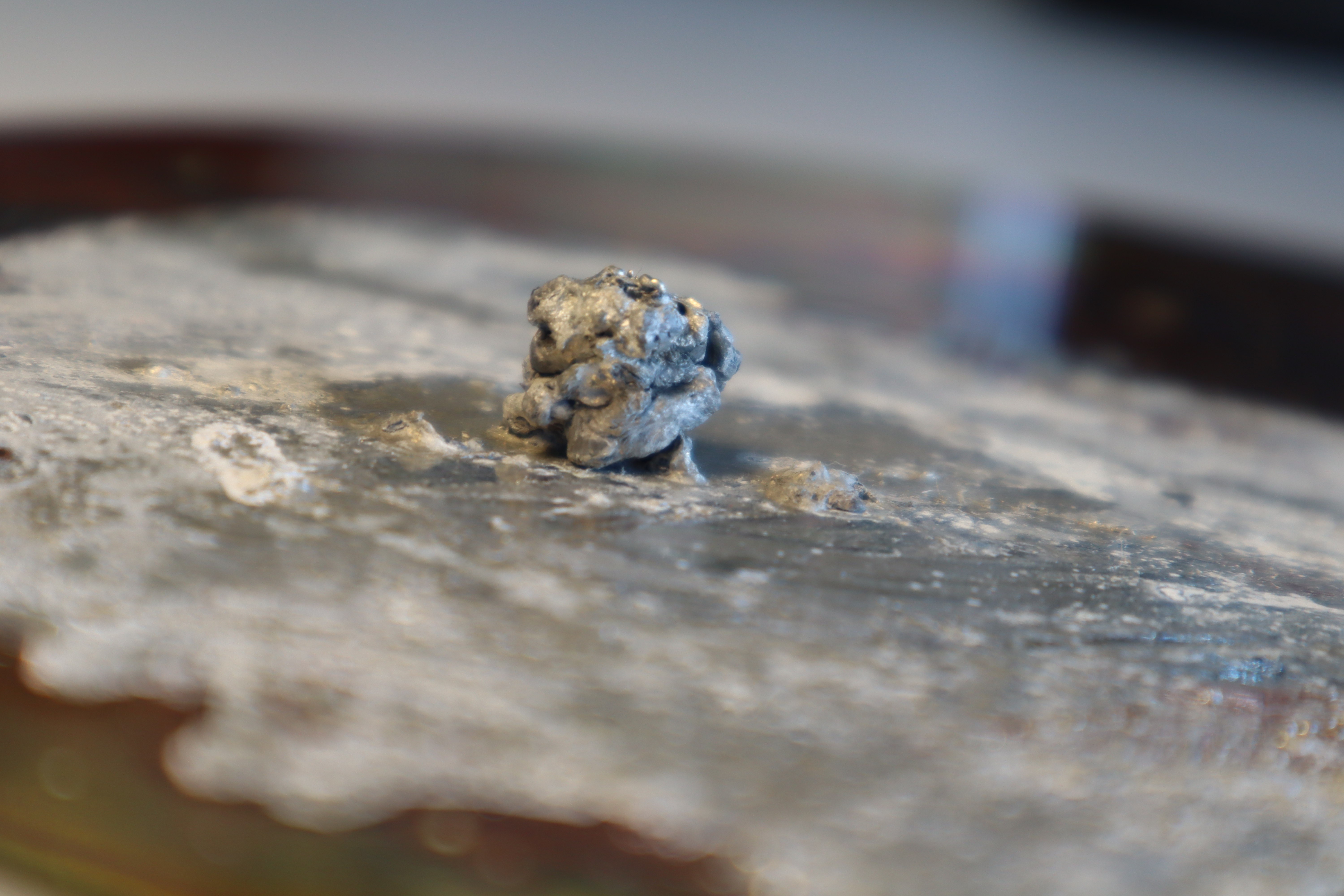
![]()
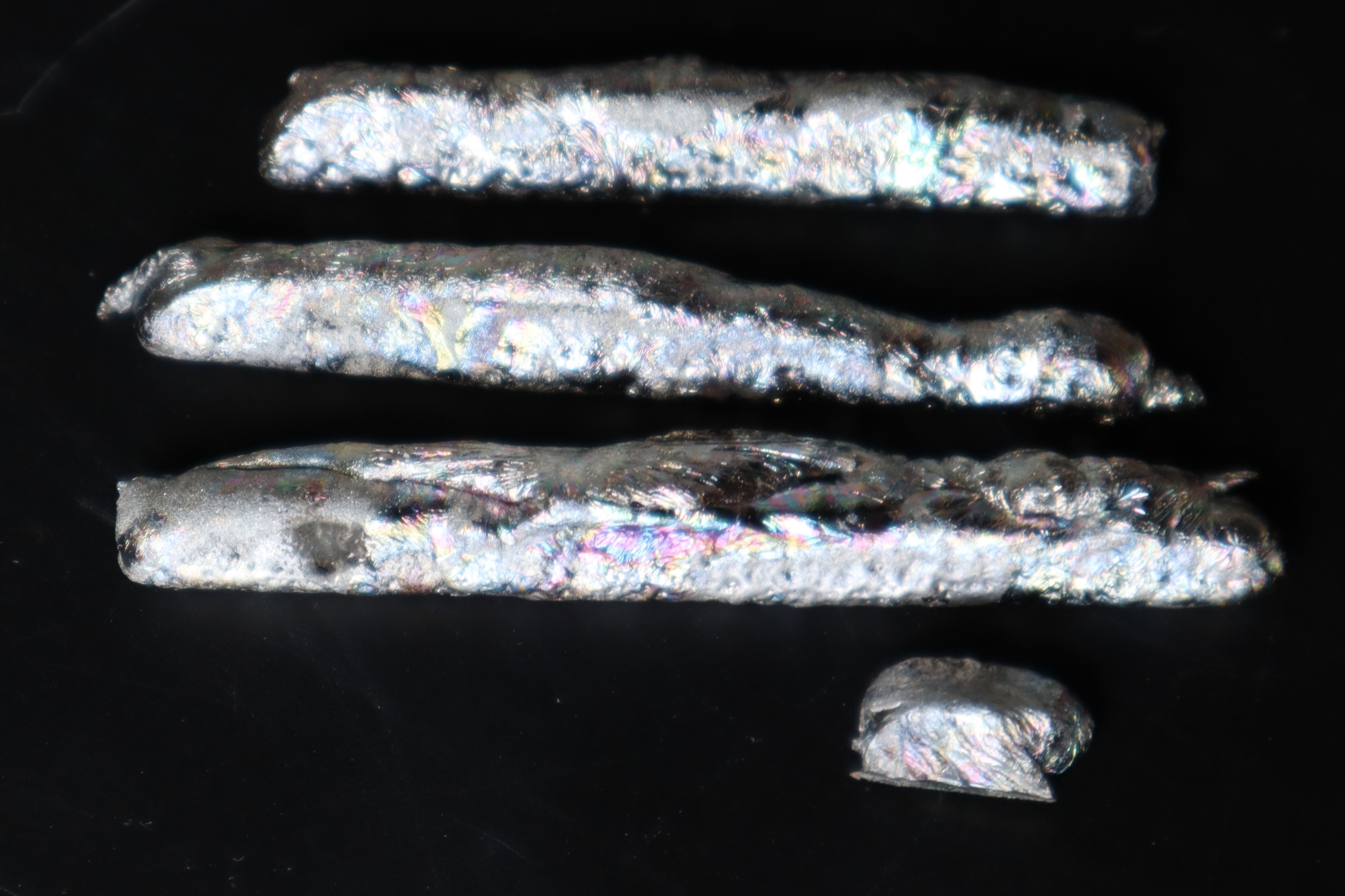
Here is a closeup of some of the experimental alloy castings: I just liked the iridescent oxide layers on this particular one and thought others might too. Tin-bismuth and tin-silver-copper alloys can be used based on solders with good results, but for the best combinations of low melting point, acceptable price (I was surprised to learn that tin is more expensive per kilo than titanium!) and high structural strength at room temperature, tin-zinc alloys are the way to go. There are ways to adapt this printing technology to copper, iron and aluminum alloys in the future, though those might ultimately have a system cost similar to a low end CNC, with tighter specs, enclosures, emergency stops, possibly inert atmospheres, etc. It would still beat other metal printing technologies by miles,
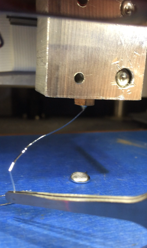
![]()
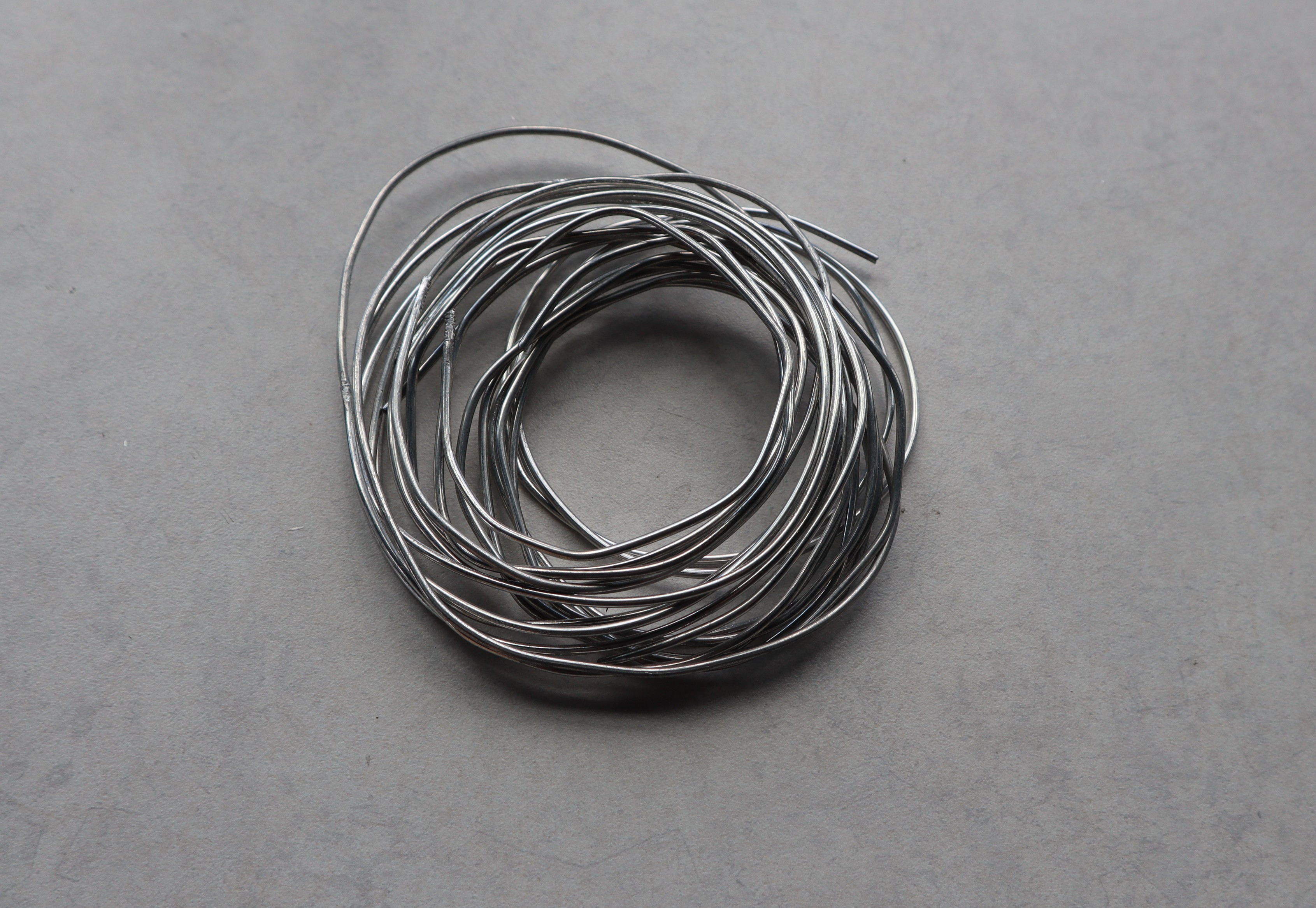
Here’s some of the completed wire/filament for extrusion. Its surface finish is smooth and the wire diameter is extremely consistent; perhaps equal to or better than industrial plastic filament extrusion precision. That’s because wire drawing is done in the solid state, making it far easier to control.
![]()
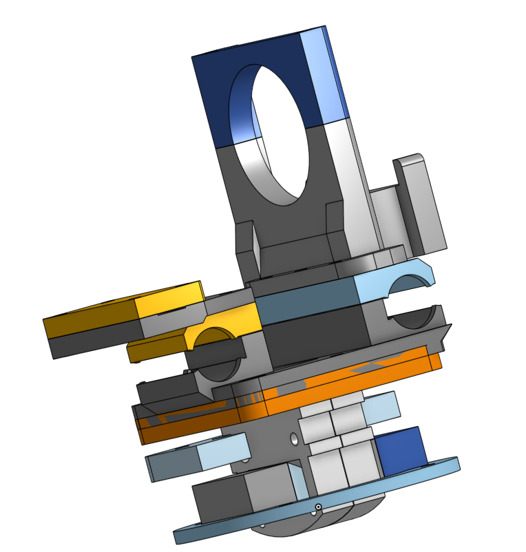
Now let's finally talk about the extrusion system, I modeled these parts for an extrusion system using a bondtech extruder and attaching to an old Prusa Mendel i2 I had lying around. No need to redesign the motion system or filament feeder, since those have already been developed. We're focusing completely on proving out the hotend functionality here
![]()
Funny story, the guy who was going to machine the hotend blocks for me canceled at the last second, so in an effort to get the system working for Midwest RepRap Fest, I hand carved a bunch of hotend blocks out of soapstone. Soapstone turned out to be surprisingly resistant to thermal shock and just tough enough for my application. Anyways Adding MHD functionality to the heater block complicates things quite a bit; a normal E3D block is maybe 1/4th the size this one ended up being. The rectangular cavities are where the polepieces of the magnetic concentrator fit in. Ideally they don't make physical contact with the soapstone and/or are insulated. The guts of the MHD system are these wicks and electrodes. For the tin-zinc base alloys I found a pure iron wick works extremely well, and also helps to further concentrate the magnetic field. The electrodes are molybdenum, which is quite wettable by tin-zinc if it has had the proper surface treatment, but not otherwise wettable and certainly not soluble. If memory serves, there are papers involving adding molybdenum nanoparticles to solders as a grain refining agent, and not even the nanoparticles dissolve appreciably over time. Wetting on ferrous alloys is still better though, so I still prefer that for the wick. The wick just barely sticks out the bottom of the heater block, and that is plenty to have the required temperature drop into the semisolid range during printing.
![]()
Here's the magnetic yoke that's meant to go around the hotend block, with a few iron filings to show off the field lines through the center. It was not easy to machine soapstone thin enough to fit through that gap
![]()
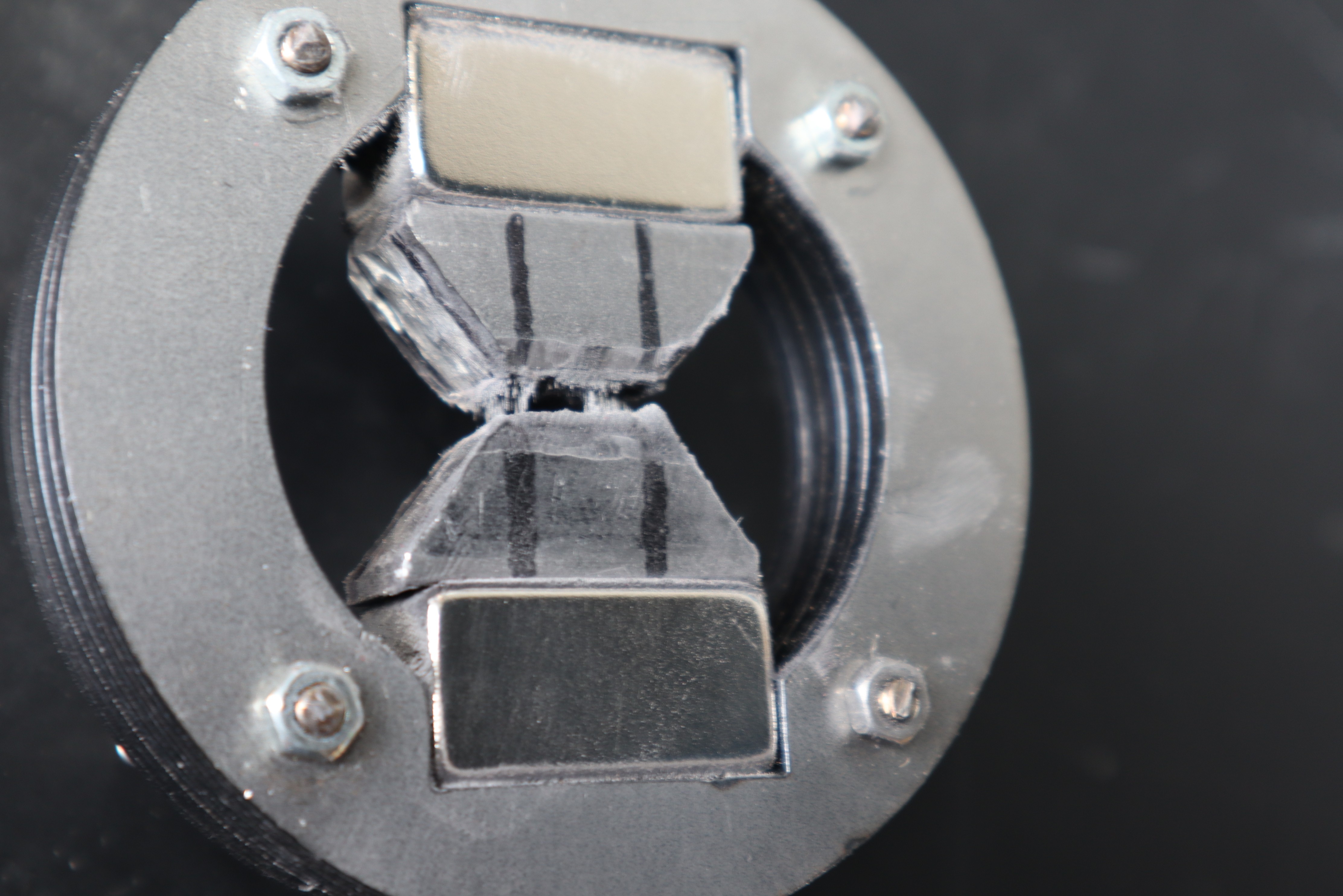
Here's the finished prototype heater block: it has a melt reservoir in the top of it with a low chromium stainless steel "sponge" to keep the melt pool in place and balance capillary forces. The bolts and nuts are titanium, so that they do not draw any magnetic field around the pole pieces but are still plenty strong enough to clamp the halves of the heater block together. The "gasket" is Cotronics castable silicon carbide; pretty convenient stuff to work with for anything involving high temperatures. Before joining the soapstone heater blocks with the castable ceramic, I coated them with a thin layer of epoxy. I learned this trick from some friends at a larger company: it allows you to join ceramics with different thermal expansion coefficients quite reliably, because the epoxy takes all the strain when the system is at temperature and it can do so repeatedly. The ideal situation is to just make it all out of castable ceramic of course. The thermistor are standard E3D stuff for compatibility.
Sadly, I didn't get it working in time for Midwest RepRap Fest: the E3D heater couldn't get the thing above 200C when it needed at least 240C to function, but I learned from this prototype and once Midwest RepRap Fest is over, it's on to V2: less surface area, more insulation, a more powerful heater, and since I won't have a tight deadline, I'll take my time and cast the hotend sections all out of silicon carbide. Once I print something with it, then I'll worry about adding the ability to change out the brush as a consumable. If anyone has thoughts or recommendations about what the next steps should be, feel free to leave a comment on the project page. Thanks for the feedback!
Shoutout to Cotronics by the way: their high temperature castable ceramics are really awesome for any high temperature fun. -
First Some Background
06/25/2021 at 02:08 • 0 commentsSemisolid Metal Printing has been attempted with limited success since about 2013. If memory serves, Lulzbot was unknowingly the very first to attempt semisolid metal printing, when they tried printing a solder with slightly off-eutectic composition. This key feature is why it worked as well as it did, though it seems they were not aware of that detail at the time. A few months later, a maker whose name escapes me (name started with an S? Post a note in the chat if you remember) attempted semisolid metal printing with antimony alloys of his own creation. From what I understand of the composition, would have been nearly ideal for semisolid metal printing, but both he and Lulzbot inevitably encountered nozzle clogging. This was due to an effect called granular jamming**, which is common in semisolid alloys but absent from clean thermoplastic. In this log entry I will attempt to include all the relevant context to understand how this extrusion system avoids granular jamming and other issues.
There are are at least five factors that must be considered when printing semisolid metals as you would thermoplastics. Firstly, the reactive wetting models describing metal are vastly different from the standard wetting models used for water or even polymers. Secondly, the range of viscosity and cohesive forces experienced by molten metallic systems differ drastically from those experienced by thermoplastics, making the Plateau-Rayliegh instability* difficult to overcome. Third, dissolution an of the nozzle/deposition head in the molten alloy must be taken into account. Fourth, metallic systems can experience granular jamming** which is almost entirely alien to thermoplastic systems, except for thermoplastic composites with solid powders added. Fifth, the material properties of semisolid alloys may have much more sensitive dependence on temperature than thermoplastics do, viscosity for example ranging over many orders of magnitude in as little as a few degrees Celsius depending on the alloy.
The Plateau-Rayliegh instability can be mitigated at the same time as granular jamming by sing a brush to guide the molten metal and printing from above the liquidus****** temperature so that the material only passes into the semisolid range as it passes over the brush. This also enables lower defect counts and higer resolution than with welding-based additive manufacturing, because "painting" the metal on is much more repeatable than the high energy, chaotically unpredictable electrical transients common in welding.
One additional consideration when printing with thin fluids is capillary forces. Kundan Chaudary Et. Al. at the Wyss Institute at Harvard attempted printing eutectic alloys and ran into the issue that the capillary pressure of fluid wetting onto a substrate tended to pull thin molten eutectic alloys through the nozzle in a variable manner, dependent on the specific shape of the meniscus formed due to surface roughness as well as on the movement speed of the nozzle. More recently, Billy Wu Et. Al. demonstrated an electrochemical 3D printer for which the meniscus was stabilized by a sponge in the fluid reservoir, balancing out capillary forces at the nozzle meniscus with the capillary forces over the surface area of the sponge. Alternatively, it is possible to use active force balancing to control deposition of thin fluids at the nozzle tip, but the use of a sponge is simple and elegant for most applications, similar to how a felt tip pen or marker works. So for the cost of a bit of flow control, it is possible to make a remarkably simple extrusion system
Semisolid alloys are often erroneously compared to thermoplastics, but their physical properties differ in some key ways which can’t be overlooked when attempting to 3D print with them. They appear viscous and shear thinning when between their solidus (where all stable phases are solid) and liquidus (where all stable phases are liquids) temperatures: in such a state they are partially molten, and behave more like wet sand than thermoplastic. This is a stable state for off-eutectic****** and peritectic******* compositions, and in between these two temperatures, such alloys are never fully solid or fully liquid. They are generally not viscoelastic materials as thermoplastics are and the liquid portion tends to have low viscosity and strong cohesion/surface tension, where thermoplastics have high viscosity and lower surface tension. Granular jamming** is possible in these systems, and many attempts to print semisolid alloys in the same manner as thermoplastics have ended in failure after being unable to overcome nozzle clogging due to granular jamming**. In the extreme case of granular jamming**, It is possible to entirely press out the liquid portion of the semisolid alloy, with the frit and the liquid fraction forming new thermodynamic equilibria with new solid and liquid fractions once separated and allowed to sit for long enough. Slightly more success was achieved with ultrasonic agitation by Lawrence Livermore National Lab, the MPI at WPI, and others, but it necessitated the construction of a nozzle as an ultrasonic horn, and the ultrasonic energy accelerated the dissolution of the horn into the semisolid alloy, detuning the ultrasonic horn until the amplitude of the ultrasound was no longer sufficient to prevent granular jamming**. The cost of that system was also likely prohibitive for industry applications. Stirring while induction heating, instead of using ultrasound, was found not to provide enough force to ultimately impede granular jamming** when the melt was substantially semisolid. When the melt had a low volume fraction of solids, granular jamming** did not occur, but then the Plateau-Rayleigh instability* prevented printing and the stream of semisolid metal broke up into droplets and did not bridge between the nozzle and the workpiece. It is generally desirable to shear a semisolid melt before total solidification because breaking up dendrites improves mechanical strength of the resulting part. Adding a brush to the extruder solves all of these issues with semisolid metal printing, and makes semisolid metal printing viable and cost effective.
Wetting of molten metal systems on solid surfaces is still not fully understood, but there are some rules of thumb you can follow to get perhaps 90% of the way there. Many of the concepts applicable at room temperature in water do not apply to high temperature metals, because the fluid medium is conductive, because covalent bond behavior is rare at high temperatures, because the energies involved in hydrogen bonding are lower than the ambient thermal energy, and because many more chemical reactions are spontaneous at high temperatures. Generally speaking, surfaces with metallic character, high surface energy, favorable lattice constants on exposed surfaces, favorable condensed matter behaviors and favorable chemistry will have good wettability for at least some molten metal alloys. Even so, the brush material must usually be engineered along with the molten alloy for best results. Aside from this, the other main factor to consider is the reactive wetting model. This model takes into account chemical reactions which may occur at the solid-liquid interface, altering the surface material of the substrate. It is possible to alter the surface material in ways which are either favorable or unfavorable to wetting. This causes droplet spreading or dewetting behaviors which depend on the surface properties of the liquid, the properties of the new solid surface, the properties of the old substrate, and the reaction rate. A special case of reactive dewetting is with oxide formation. Because oxygen is common in our atmosphere, some may dissolve into the molten alloy and diffuse to the brush surface, oxidizing it and causing dewetting. Therefore when operating in ambient atmosphere containing oxygen, it is desirable to have the brush be less reactive and less electronegative than the molten alloy, so that the molten alloy galvanically protects it. This introduces some oxide to the molten alloy, but these oxide layers are disrupted by the brush as the system prints and may be negligible when the materials and process temperatures are properly chosen. Other means of protecting the workpiece and brush from oxidation (and sometimes nitriding) also exist, but galvanic protection often suffices as an inexpensive and elegant solution. Solubility in the molten metal is also usually correlated with good wettability, but is not always desirable for 3D printing. Sometimes materials which dissolve in a molten metal have very tenacious liquid coatings due to the change in composition and rheology******** very close to the material surface, the quintessential example being copper metal bonding to tin solder, where brushing off the solder after wetting may actually take some effort. Dissolution is a reasonable concern because it can alter the composition of the feedstock alloy in an undesirable way or damage the brush so that printing fails, and usually liquid metals wet onto things which they also dissolve well. To mitigate this concern there are two strategies: using materials which are wettable but not soluble in the feedstock alloy, and using materials where dissolution is manageable or even beneficial to the feedstock alloy. Refractory materials tend to dissolve more slowly because they have lower diffusion coefficients and are therefore desirable as print brush materials if they are wettable. Ferrous alloys also often have sufficiently low dissolution rates and good wetting properties to be used as brush materials, and often their microalloying into the feedstock material can be beneficial to its mechanical properties. Another point of interest is that sometimes, materals with low but nonzero diffusion into the molten metal enable the formation of Kirkendall voids*********, where more of one metal phase diffuses out of a region than the other phase diffuses in. These voids can serve as nucleation points for dewetting events, but may also be manageable depending on how severe they are. Lower process temperatures reduce the diffusion rate and retard dissolution and Kirkendall void formation.
*The instability which causes streams of thin fluid to break up into droplets.
**Where solid phases in the molten fluid stick together to prevent flow.
***An effect which draws current-carrying conducting matter towards the center of the current.
****Where different vaporization rates of the alloy components induce a strain on the surface of the fluid.
*****Where active trace elements modify the diffusion rate and surface tension of the fluid.
****** Eutectics are alloys which have a lower melting point than their component ingredients. Off-eutectics generally have a solid and liquid phase above their solidus temperature and below their liquidus temperature, and will retain those same phases during solidification and cooling. The important point is that they have a semisolid range.
******* Peritectics are alloys with a semisolid range where the solid and liquid phases turn into a third phase while cooling and solidifying. The important point that they have a semisolid range.
******** Fluid properties of a material
*********Holes at the interface between two materials which form due to diffusion effects