These are cables that can be used together with universal and panel-specific controllers from China. If you have a suitable controller but the cable is not compatible with your screen's pinout, it won't work ;-( The headline is usable as a search term on eBay/Aliexpress/etc. so you can find a suitable listing.
FIX-30P-D6
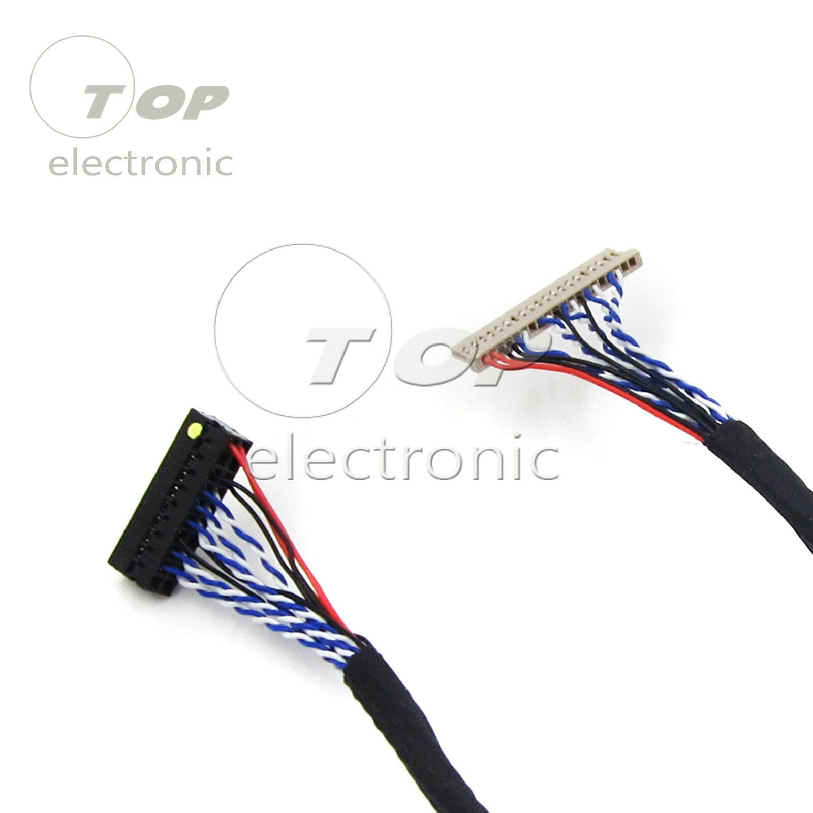
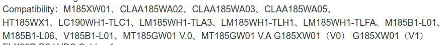
A cable with the FI-X 30-pin connector that uses a single-llink 6-bit pinout - if you have a 1280x800 screen, this is what you'll be using, in all likelihood.
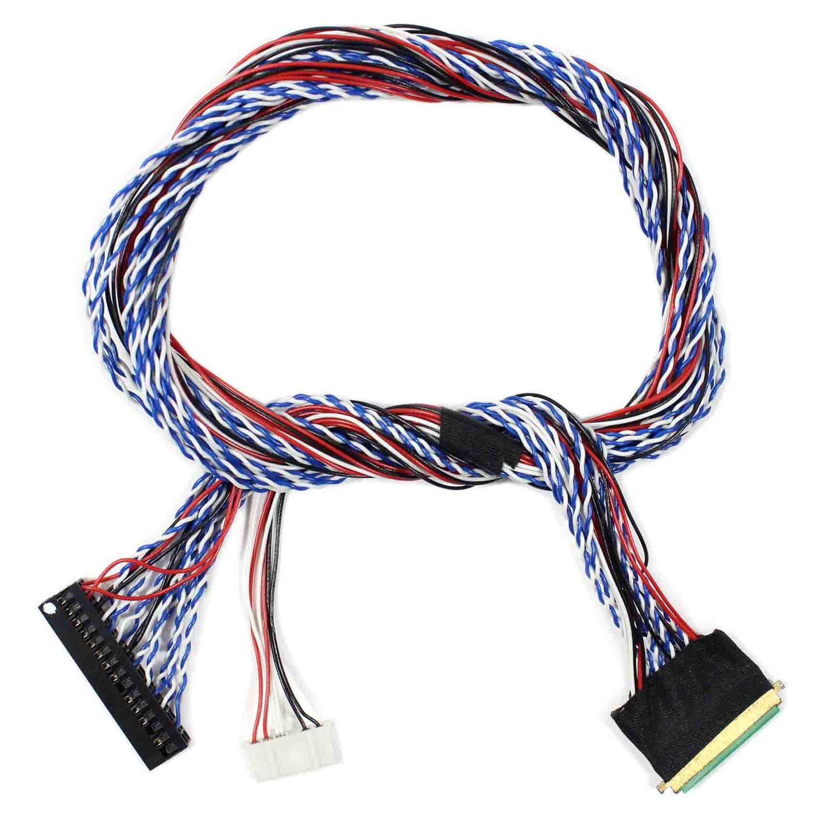
A cable with the FI-X 30-pin connector that uses a dual-link 8-bit pinout - this kind of cable is used for desktop LCD monitor screens. Funnily enough, this cable costs $3, and a MT561 board bundled with such a cable costs $5, which is to say, if you need such cables, you might as well get some MT561 boards to go with them.
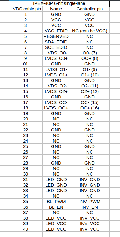
A cable with the IPEX 40-pin connector that uses a single-link 6-bit pinout and allows you to interface the LED backlight pins on the same connector to your controller. If you have a 1366x768 LED screen, it's most likely to be using this cable.
A cable with the IPEX 40-pin connector that uses a dual-link 6-bit pinout and allows you to interface the LED backlight pins on the same connector to your controller. If you have an LED screen with resolution above 1366x768, it's most likely to be using this cable.
A cable with the DF14 connector that uses a single-link 8-bit (compatible with 6-bit) pinout. If you have an old 1024x768 CCFL screen, it might need such a cable.
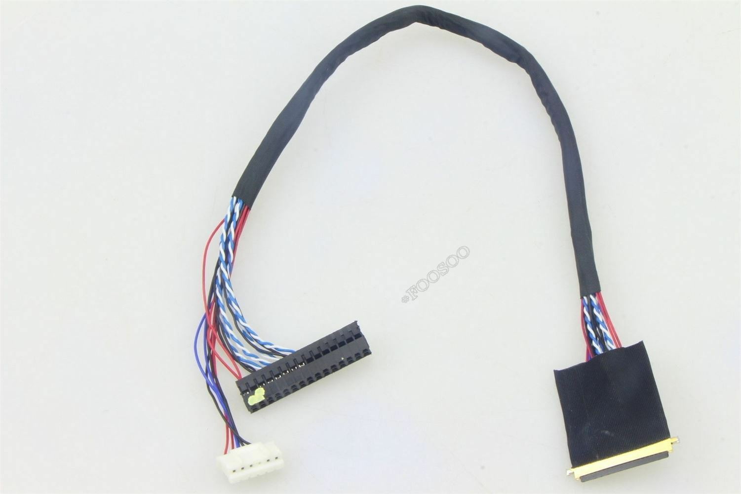
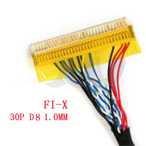
A cable with the FI-X 30-pin connector that uses a single-link 8-bit pinout. If you have a 18.5" 1366x768 panel for a desktop monitor, it will most likely use this cable.
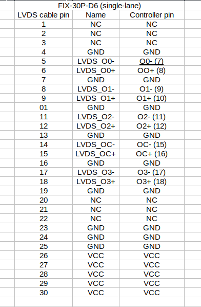
I've previously mentioned that, funnily enough, single-link 30-pin CCFL-panel LVDS cables are commonly referred to as FIX-30P-D6, and dual-link cables for the same kind of panel are referred to as FIX-30P-S6. I've also mentioned that, in my experience, there's single-lane panels that don't work with dual-lane cables, with different results - from having no picture to showing rainbow colors, green-tinted screen or similar glitches. (My current theory is that some laptop panels short the unused pins for the extra LVDS lanes that the panel doesn't use, and this makes the MT6820 controller go haywire because its LVDS output pins are shorted to GND).
I'm not even mentioning the fact that single-lane cables tend to be more expensive than dual-lane cables, even though they have less wires in them.
All of that is nice to know.
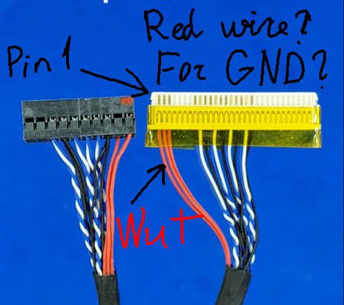
However, what the fuck does this thing mean?
---------- more ----------
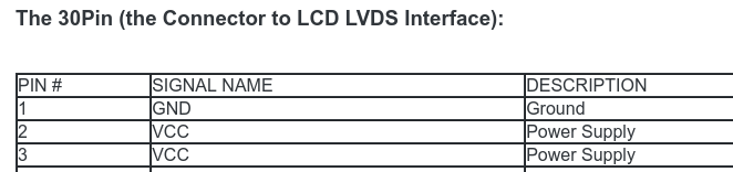
Why are there three VCC wires in positions 1-3, when pin 1 is GND? That's going to burn out the diodes forming 3.3V backlight power, isn't it?
Did they accidentally copy part of the FIX-30P-D8 pinout, which has three VCC pins, but in the opposite location?
As an aside - what even is this specific FIX-30P-D8 pinout, which display has a single LVDS link in the middle of connector?
Oh, a very specific set of 18.5" displays, it seems. I sure hope people don't buy this cable on accident!
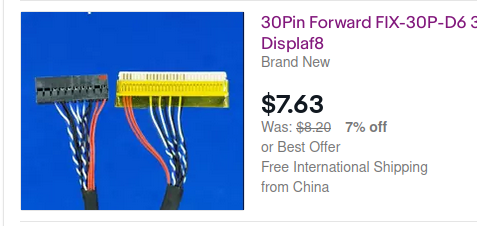
But yeah, what's up with FIX-30P-D6?
I haven't bought any of these specific cables to check - I do plan to. However, a bit of eBay listing picture investigation shows that not everything is as bad:
This specific cable simply uses a red wire for a GND connection. Certainly not a controller-killing mistake, also certainly a source of confusion for people who actually look at the pictures.
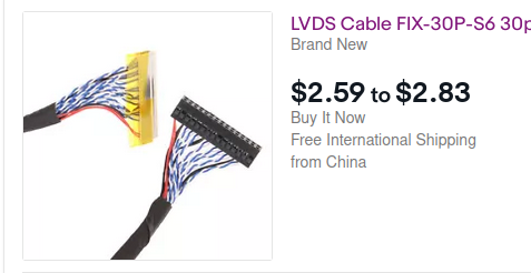
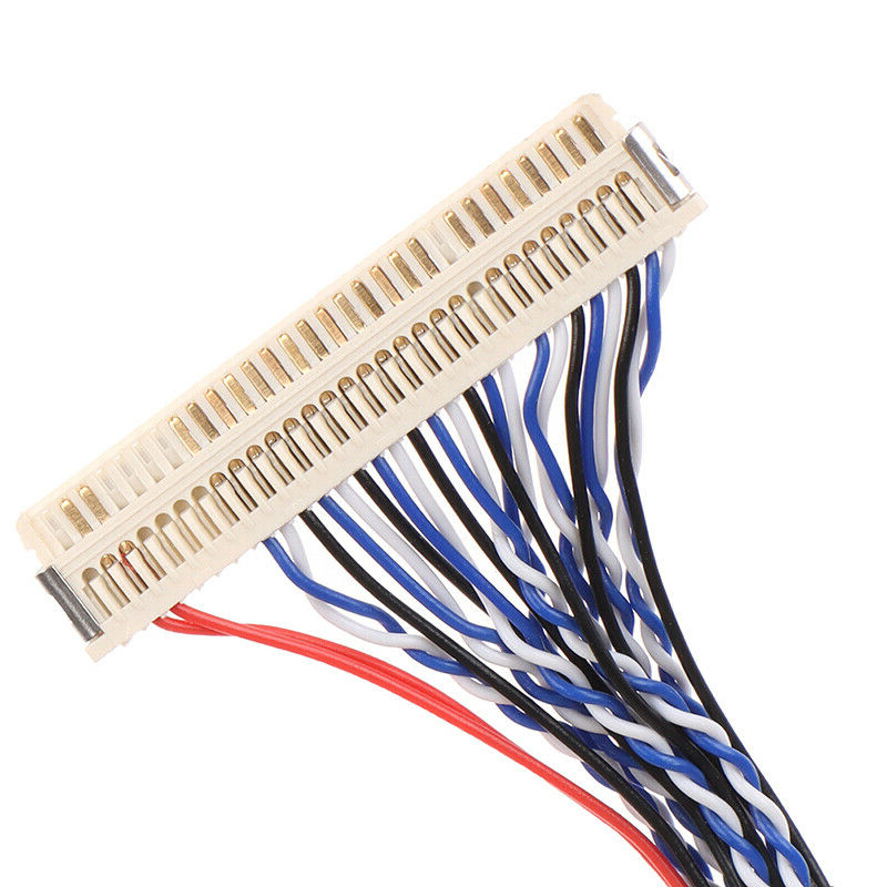
This mistake isn't made with FIX-30P-S6 dual-link cables:
I guess they wisened up? Hopefully, that is the case.
And to sum it up, FIX-30P-D6 won't burn your controller, they're just confusing.
VGA to LVDS converter with jumper-programmable resolution
Dual-lane and single-lane LVDS support
Has support for EN+ADJ inverter output
Has a pin header for wiring up VGA signals
13 different resolutions supported:
Resolutions (ranked according to subjective preferability ;-P), plus jumper combinations for different LVDS modes :
---------- more ----------
1920x1200 (A+B+G for "2-6")
1920x1080 (A+C for "2-6", A+B for "1-8". A+C+G for "2-8")
1600x1200 (A+E+G for "1-8")
1680x1050 (A+D for "1-8", A+D+G for "2-6")
1600x900 (A+F+G for "1-8", B+G for "2-6")
1400x1050 (D+G for "2-6")
1440x900 (A+E for "1-8", C+G for "2-6")
1280x1024 (E+G for "2-8", A+F for "1-8")
1366x768 (B for "1-8", C for "2-6")
1280x800 (F+G for "2-6")
1024x768 (G for "6*2-1" (whatever that is), A+G for "2-8", E for "2-6", D for "1-8")
1024x600 (A for "2-6")
800x600 (F for "8-1")
Not all of the LVDS modes listed are actually correctly labeled - for instance, with 1280x800, it's listed as LVDS-2-6, but 1280x800 panels never actually seem to have a 2-6 connection, all of the panels I've encountered using 1-6 - and they're happily driven by the controller when using an 1-6 cable.
Surprisingly, approximately a third of all the panels I tested fail in some way when connected with a 2-6 cable - one had a fullscreen green image, a couple of them refused to work straight away, one would get filled with rainbow colors from top to bottom and not have any reasonable output. This is very weird because one doesn't usually expect the second LVDS lane pins to even be connected on the panel's LVDS connector in any way that'd impact anything at all - however, disconnecting half of the LVDS pins (on the MT6820 board's side) belonging to the second lane (that shouldn't even be sending anything) resulted in all panels working flawlessly. Since figuring this problem out would require me to unfold the controller PCB and possibly damage it in the process, I didn't bother investigating further, and just had half of the cable disconnected while working on these panels.
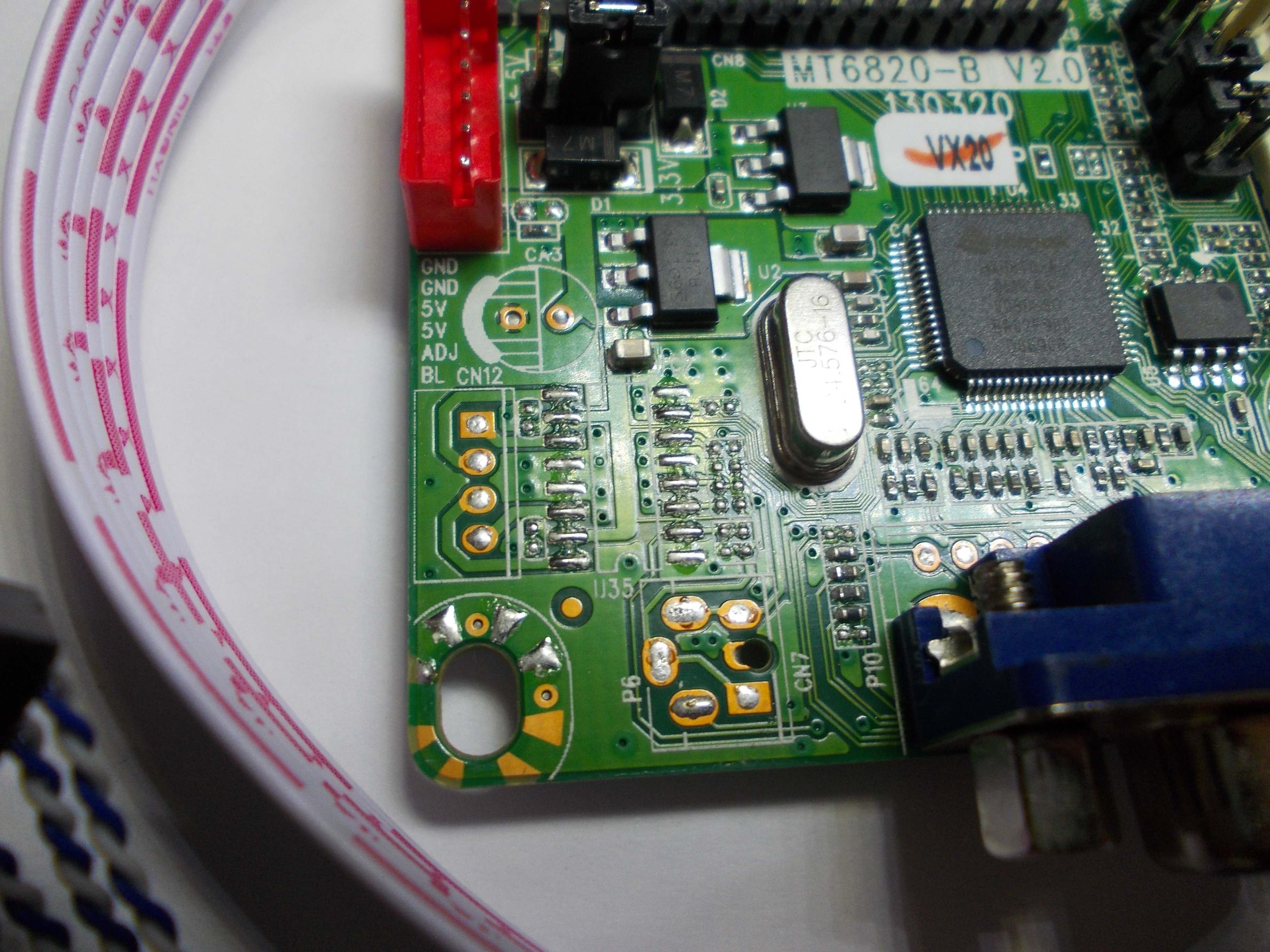
Hardware
HX6810-A IC, no datasheet to be found so far, but please do keep looking =)
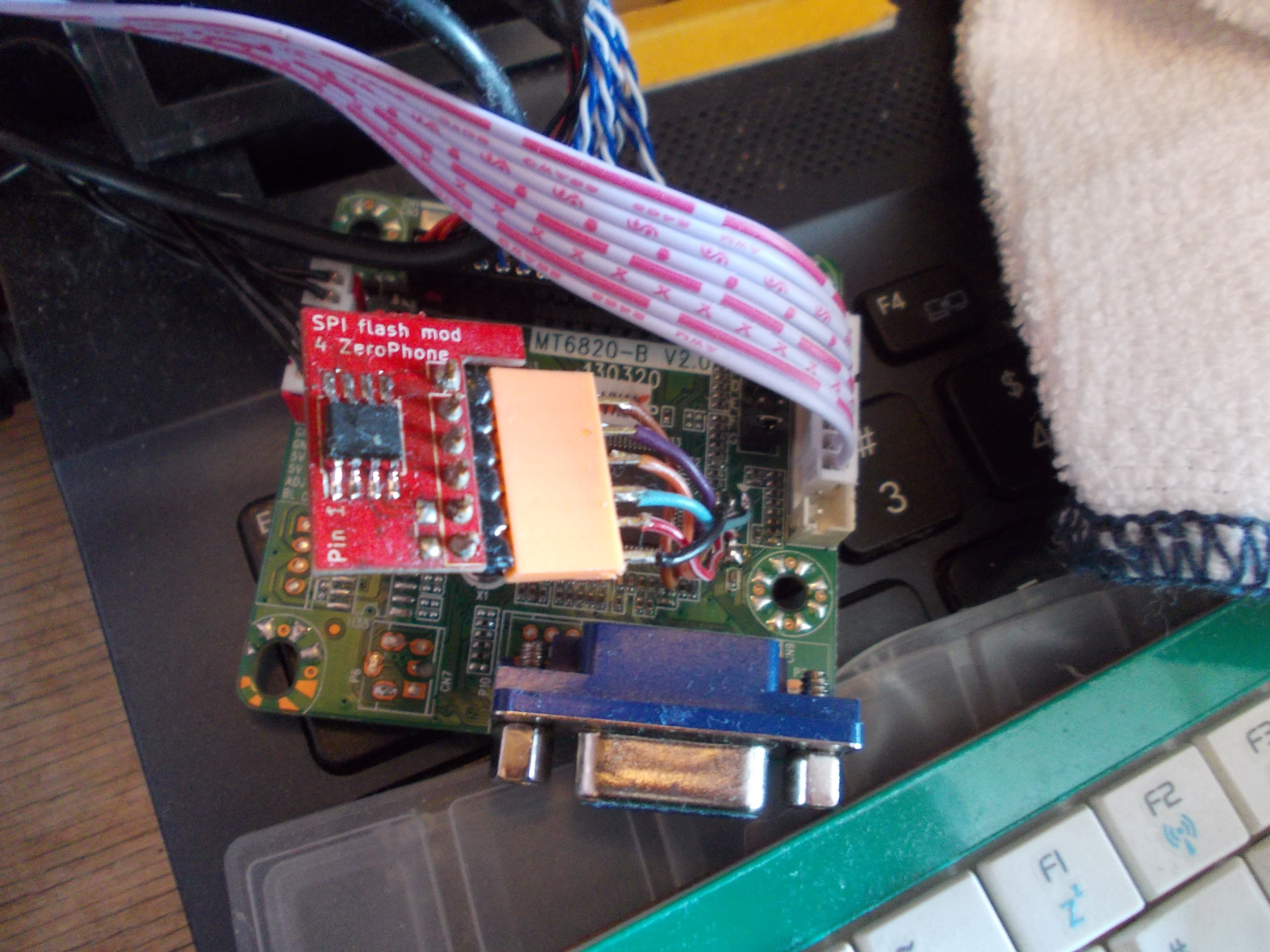
Has an onboard W25Q40.V 512kb SPI flash that contains the HX6810 IC firmware
7 jumpers for configuration, they're 2mm jumpers, and every board seems to come with 3 - it's easy to lose them, so try not to!
Has a connector for a 7-button+2-LED board, but comes with a 5-button+2-LED board, and the extra two button inputs don't seem to do anything when shorted to ground.Connecting the cable correctly:
There's a standard 2mm 30-pin header for the LVDS cable, the signals from it are also available on an unpopulated 1mm X-pin (TODO) FPC connector.
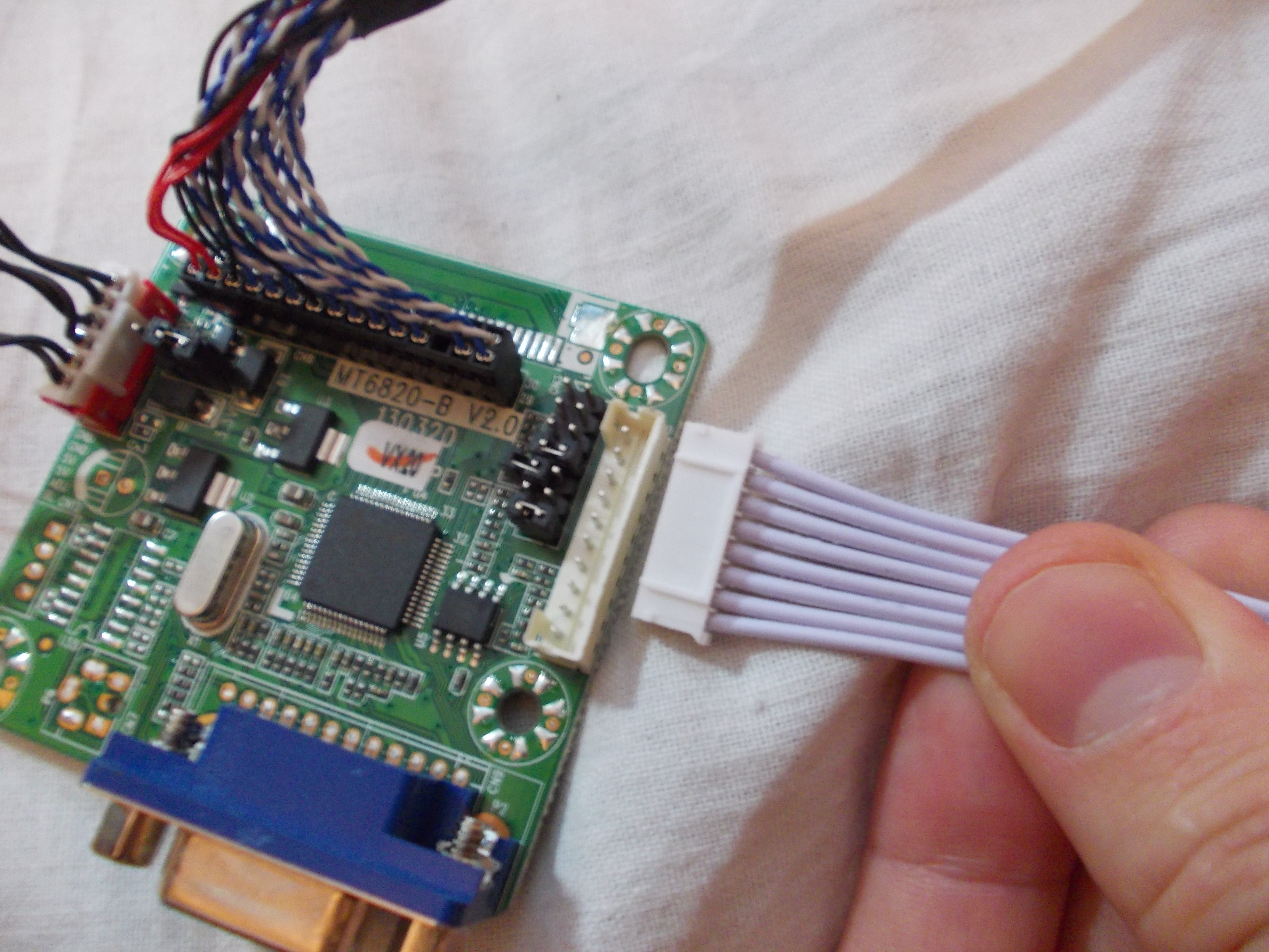
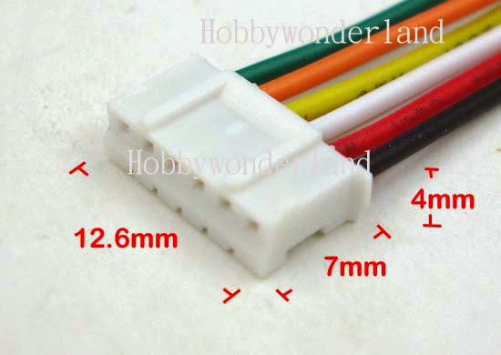
The board expects a 5V input, and doesn't have a power input connector as such. It is commonly powered through the "inverter" connector. The inverter plug expects a 6-pin JST-PH cable.
Onboard, 2 voltages are created using two linear regulators - 3.3V and 1.8V. 3.3V from the regulator seems to go to the controller and not the panel.
3.3V panel power seems to be created from 5V by chaining two SMA-packaged diodes together:
Oh boy, does all of that not look good for power consumption.
Board has a footprint for a PAM8403 speaker amplifier, so one can be soldered onto the board - but it is rarely populated.
Firmware
Yep, I did dump it!
The board emulates an I2C EEPROM so that the signal source (PC/SBC/whatever) can read the EDID
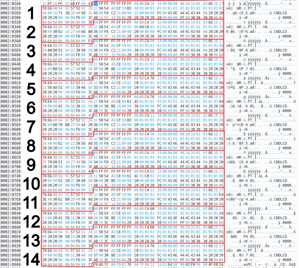
The EDIDs are stored on the SPI flash - from an SPI flash dump inspection, there's 14 EDIDs all in one location.
There's also an EDID stored in a separate location, perhaps a "default" one? That makes for 15 different EDIDs.
OSD strings are stored as null-terminated strings - so, if needed, one can change the OSD strings easily ;-P
The board does generate extra EDID data for certain resolutions! It adds EDID extensions with, I'd guess, resolution information. I'm likely going to make a setup that'll go through all the resolutions while having the board connected to a VGA port, setting the jumpers with a PCF8574 board and power cycling the setup with a relay - and then see what data we can collect. Until then - I can't really tell a lot about EDID, other than say with certainty that I've had success editing the EDID data before, but now I'm not certain this will actually apply to every EDID combo there is.
One thing is certain - the 15 EDIDs from the firmware are actually used by the firmware as the base for the new EDID, as most EDIDs I could get the board to output contain the "CNDLCD\x0a" string, which only appears in the firmware embedded inside the EDID blocks.
However, the board outputs EDIDs that don't contain "CNDLCD\x0a" as the manufacturer name, for instance, when an AD (1680x1050 LVDS-1-8) combination of jumpers is used. First 128 bytes of such an EDID:
The research continues. I shall upload the binary dump in the "files" category so that anyone can take a look at it.
The firmware data does contain OSD strings that indicate there's a factory setting menu, just like on M.NT68676 boards. I haven't checked whether the M.NT68676 factory menu combination works on these boards, hopefully, it does.
Settings (i.e. OSD language) are also stored in the same SPI flash - dumping flash, changing settings and then restoring the flash image also restores the previous settings. The address where the settings are stored isn't determined yet.
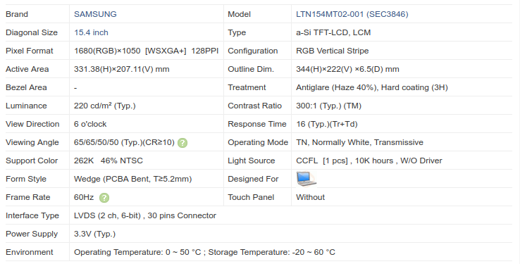
The most important step, arguably. It's going to be written on the back of the panel, on a sticker somewhere.
Of course, there's all kinds of text on stickers on the back of the panel. The model number is going to be displayed prominently, but not always. Need some panel model number examples, as in, what kind of number are you looking for? Here's some:
---------- more ----------
Samsung:
LTN154MT02-001 (15.4")
LTN154P3-L02 (15.4")
LTN141P4-L02 (14.1")
LTN121W1-l03 (12.1")
LG:
LP171WP4 (17.1")
LTN154AT01 (15.4")
AUO:
B154EW02 (15.4")
B154EW08 (15.4")
Toshiba:
LTD141EM5F (14.1")
LTM14C453 (14.1")
Hitachi:
TX36D98VC1CAB (14.1")
TX38D85VC1CAB (15.0")
As you can see, it'll typically contain a few letters in the front, then three digits denoting the panel's diagonal in inches*, then a few more letters and numbers. There's some more esoteric manufacturers (i.e. Hitachi), but overall this is what you can expect.
* the last Toshiba model number is a bit of an exception in that it's 14.1" but the model number only contains "14")
Can't recognize any model numbers?
Pop into our chatroom, post decent pictures of stickers on the back, and we'll try to help you =)
Alternatively, if there's a computer you can plug this panel into, you should be able to read the panel's EDID using Windows or Linux tools [TODO: article] - the EDID info should contain the panel's model number!
Got the number, what now?
Plug it into Google =) Does a Panelook.com page come up? If so, great, you're almost there! This table is what we're interested in:
This contains most of the information you'd be looking for.
What are the important fields?
Resolution - a general good-to-know, and also needed for setting up a universal controller.
Viewing Angle - isn't needed to set the panel up, but it's good information on whether the panel will fit well, wherever you want to use it. For instance, if you're making a small arcade machine, you'll want to align the panel in a way where the player won't have any problems watching the game unfold on the screen.
Interface Type - most important parameter, determines the kind of cable you'll have to use with the panel, and pretty accurately predicts how the panel will be wired. Is important if you'll be setting up a universal controller - panel-specific controller setups usually come with the cable wired correctly!
Power supply - not crucial to know, almost always is going to be 3.3V, in case it isn't, you'll likely want to adjust your universal controller's panel voltage. Again, is not important for panel-specific controller setups.
No Panelook page?
If your panel number consists of two parts and second part is short with i.e. 4 letters and numbers (example: LP154W01-TLD1), put only the first part (that'd be LP154W01) in the Panelook search bar and see what they have to offer.
Usually, the second part is less important - it mostly specifies surface treatment (glare, matte, antiglare, antireflective etc) options, as well as might indicate slight differences in the panel outer dimensions, and panels with the same first part of the model number will share important parameters like the interface type, resolution and power supply voltage.
Otherwise, look it up on Google some more. You're bound to find the panel resolution (and maybe the viewing angle) eventually, and if you luck out, you'll also find a datasheet, which will tell you more about the interface type...
If not, but if your panel uses a common connector [TODO: article], chances are, you'll be able to wing it =)
Datasheet
Sometimes, you'll want to have the panel's datasheet. In practice, it's usually not important - for instance, an overwhelming majority of the 1280x800 15.4" panels out there have the same pinout (every single one out of the 18 such panels I have does), and as time progresses, standardized pinouts are more and more common.
However, what if your panel has a wacky connector? Or what if you're worried and want to doublecheck everything? There's two ways - find a panel datasheet PDF online using Google, or buy it on Panelook if you feel like spending money. I've never had to buy any datasheets on Panelook, however, and if that's ever really needed, come to our chatroom and we can probably figure something out =)
The datasheet will contain the panel's pinout, which is the only thing you usually want to check. Does it fit one of the common cables? [TODO: article] If so, you're basically set.
! These are LVDS screen guidelines! For eDP screens, I'll have a separate guide later on =) !~
Fundamental ways to make use of a LVDS laptop screen
Use a pre-configured and pre-wired "screen-specific" controller
Should work out of the box - plug&play
Might have multiple display inputs - in fact, there's a common board which has 3 separate inputs (VGA, DVI and HDMI), and they're all separate inputs you can switch between, effectively giving you a 3-input display for all of your tinkering needs!
Most expensive option - in fact, prices vary wildly, you can be overpaying from $5 to $20 for a controller "programmed for" a screen that is not actually hard to program a controller for, -the eBay listing price can be increased because of the screen rarity or popularity, the firmware will be the same.
Power requirements are prohibitive for portable projects - will typically need 12V, unless the board is tweaked for better power consumption
These boards often use linear regulators heavily, so power consumption will be high and a lot of power will be wasted as heat, which is bad for battery-powered applications
If there's only a "TV board" controller available, with antenna jack input and a USB port, these functions will consume extra power and might make your project's UX a bit worse
Might have a speaker amplifier on it - if that's what you need, great, however, sometimes it'll just be another power-wasting addon
CCFL inverters provided with these screens tend to be bulky, so harder to integrate in i.e. a laptop rebuild. It is likely that you'll be able to use the original inverter, though.
---------- more ----------
Use a "universal" controller and wire it all up yourself
Might need a bit of cabling work unless you buy suitable LVDS cables separately
Universal controllers typically only have a VGA interface - adding a HDMI to VGA adapter will increase power consumption
Using gertVGA adapter on GPIOs should negate some of that, but at cost of 20+ GPIOs
Power consumption is still prohibitive because of the linear regulators, but can be tweaked if you add a separate DC-DC
Both CCFL and LED (whichever you have) driving circuits will likely still need 9V+, however, with a separate step-up DC-DC or direct battery power, associated power losses can be decreased a lot
Use a LVDS interface available on your SBC/FPGA/motherboard
Is not always an option, sadly
Will need some configuration research for your specific board
Will need some wiring work, maybe even a custom PCB!
Is very low-power! Your board's GPU will be doing most of the work
Same as with the "universal controller" option, need to take care of the CCFL or LED backlighting
Is there a screen-specific controller available for your screen?
Looking up your screen's model number in the eBay search bar typically helps you find it.
Do you want to use one?
Reasons to use a "screen-specific" controller
You want it to "just work"
You want it to have multiple inputs
Increased power consumption is OK
You have the budget for it
The possibly-present speaker amplifier is something you could make use of
Reasons to avoid using a "screen-specific"controller:
The computer you're connecting to has an LVDS/TTL interface already
You want to conserve some power
You want to conserve some money
You want to have fun and learn about laptop displays in the process
This knowledge database project has a lot of info that will make it easier for you ;-P
In case of CCFL backlight, whichever out of these three options you pick, it is highly likely that you'll be able to reuse the inverter that came with the display originally.
Decide to use a screen-specific controller? Then go buy one! =D
[TBD] Proceeding with not using a "screen-specific" controller
So, you'll either use a universal controller, or some kind of LVDS interface present on your SBC/motherboard of choice.
What are the steps you need to take anyway?
Powering the backlight - will help you determine if the backlight works and also help you check the screen for scratches. This step is optional, but will help you save money by not investing time&resources in a screen that migth be broken. If you know the screen to be working well, you can do this step a bit later.
If the backlight is CCFL, you will likely be able to power it easily by reusing a laptop inverter [TODO: article]
If the backlight is LED, then the LVDS signals and the backlight signals will be on the same cable. To test it, you will need to either solder 4 wires to the LCD screen controller board, or find a cable that plugs into the LCD and reuse that. [TODO: article]
This is a page where you can find common laptop/desktop LCD panel pinouts and see if your laptop screen's pinout matches any one of them (it likely does!).
Common pinouts:
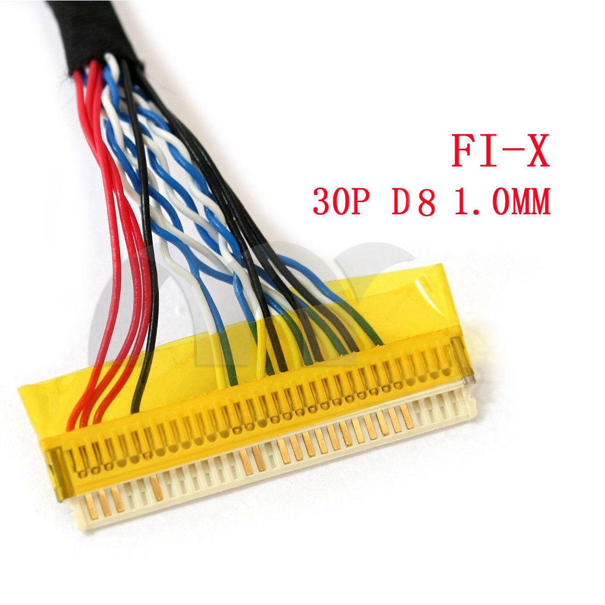
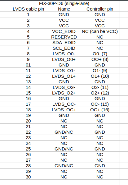
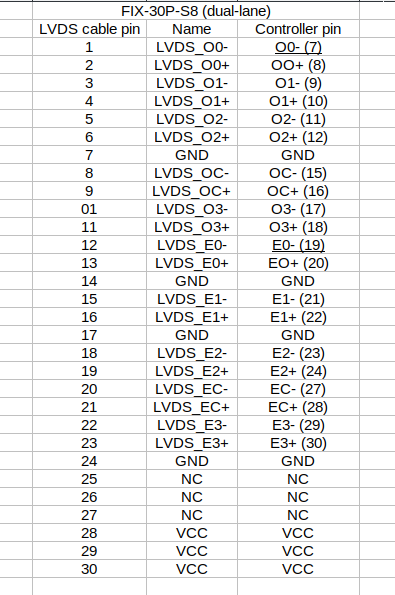
A: FI-X 30-pin connector single-lane 6-bit pinout
[TODO: insert laptop panel connector photo]
By far, the most common pinout for lower-resolution CCFL panels. If you have a 1280x800 panel, chances are, it's using this pinout.
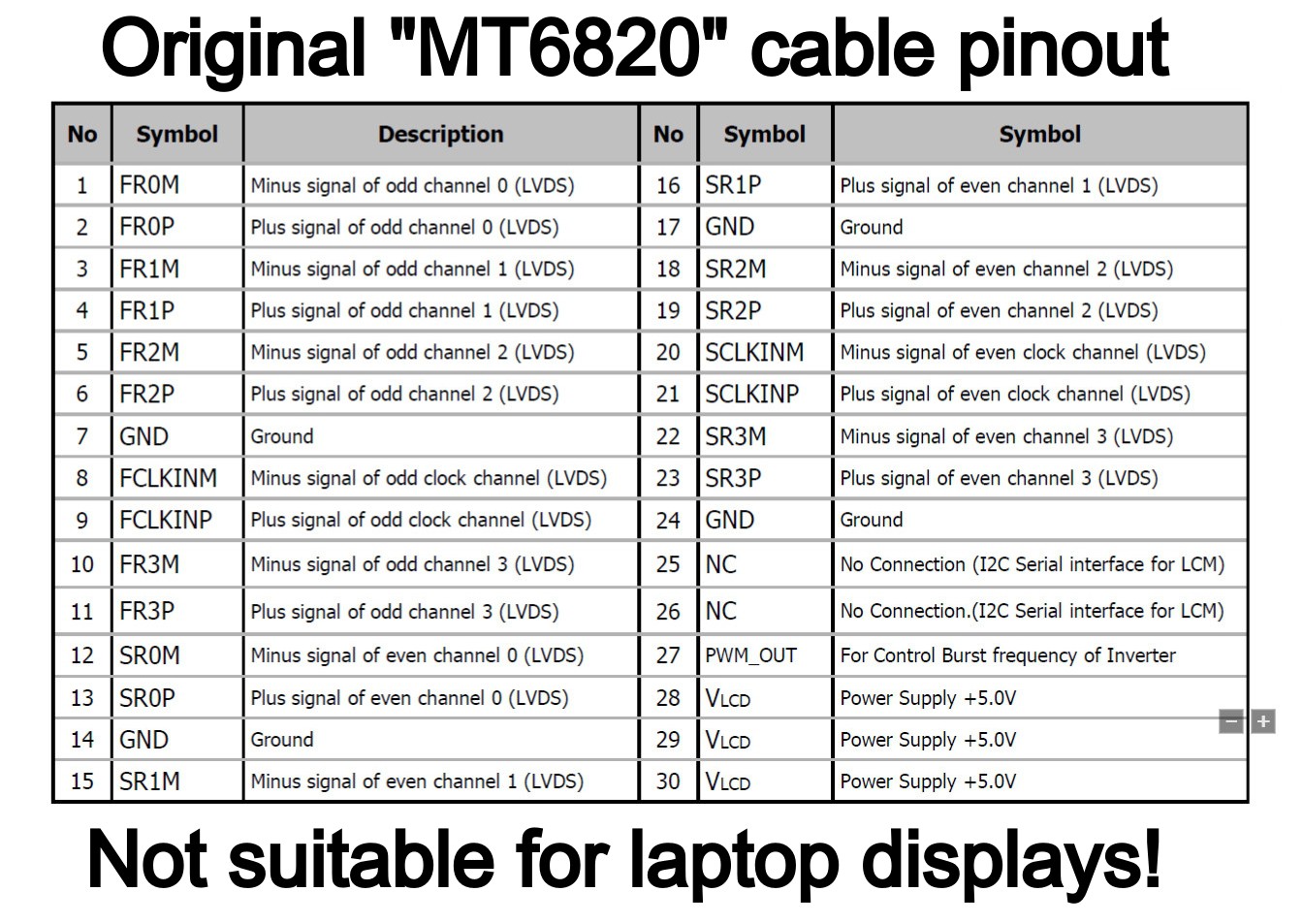
This is a pinout for desktop LCD monitor screens - laptop panels do not use this pinout (if there are some, let me know). If you're ordering a MT6820 (MT561) board, it will arrive with a cable that has this specific pinout and is therefore incompatible with laptop screens - as you're likely here to reuse a laptop screen, you will want to either rewire the cable you get, or order a suitable cable (for either A or B pinout, whichever you need) from the beginning.
This is a pinout for older, 1024x768 and similar laptop screens, CCFL-equipped ones. 1024x768 screens used both the A pinout, this pinout and even a different pinout with a connector I haven't made a description for yet, so if you have a 1024x768 screen you'd like to reuse, there's three possible options and you need to check which one you have before you buy/reuse/build a cable.
This is a pinout that's, apparently, specific to a select range of 18.5" 1366x768 displays used in desktop LCD monitors. It's not compatible with either A, B or C pinouts, and requires a specifically wired cable.
In some datasheets, the pinout will list extra pins - one before and one after the main pins, both would be described something like "shield GND". So, for a FI-X 30-pin connector, you might find a pinout in your datasheet that lists 32 pins instead of 30. These two pins are not "real" connector pins and you shouldn't worry about them - they're pins that the manufacturer decided to mention for some reason, but they're not relevant when you are actually connecting to the panel.
I have heard, though haven't yet confirmed, that sometimes manufacturers mean different things by "odd" and "even" when it comes to LVDS links. If you connect your display and it works great but has swapped lines, you will likely need to rewire your cable =(
Anyway, upload them in a private chatroom, then get image URL and link it here => perfection
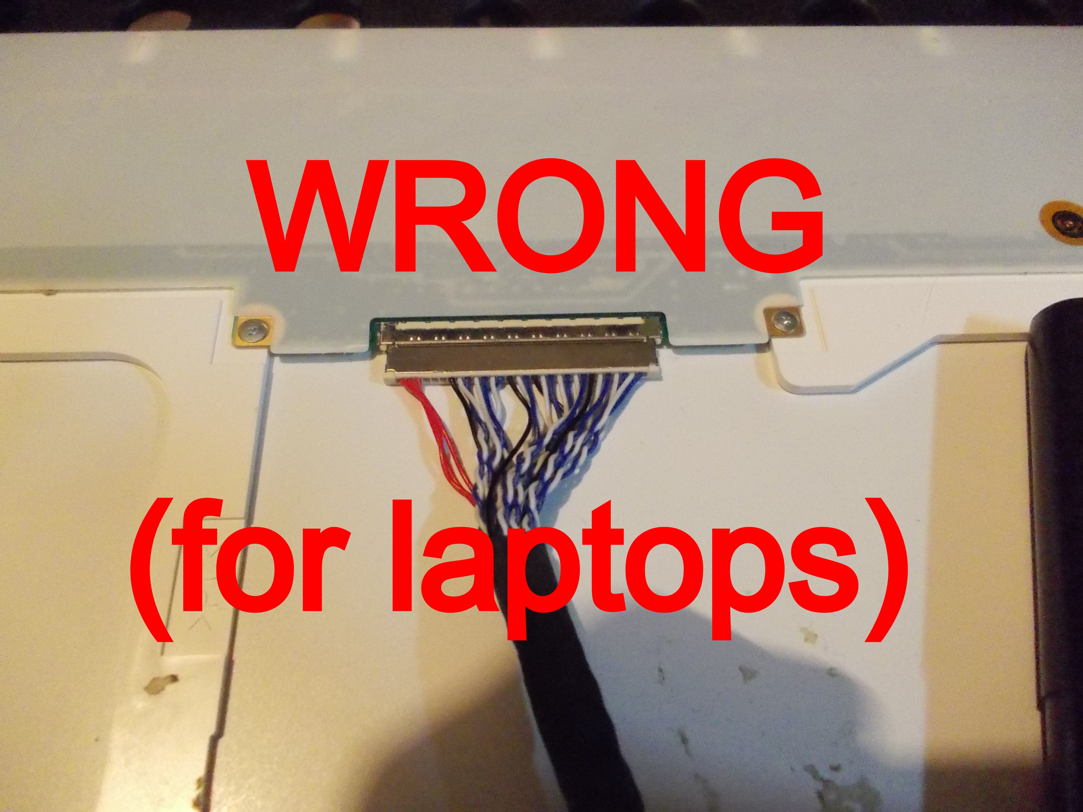
So, first of all, *ahem*
Okay? You will burn your panel if you don't do that.
Now, let's see what's up.
The default "MT6820" or "MT561" LVDS cable (that you get if you don't specifically buy this board listed as compatible with laptop screens) is not compatible with laptop panels! I've seen tons upon tons of angry messages on Aliexpress about how "the board didn't fit my laptop display", and hardly enough awareness of the problem - most people chuck the board in a drawer and never try again.
Two things you can do:
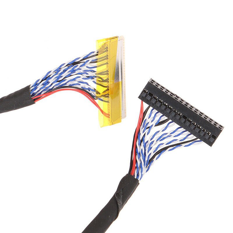
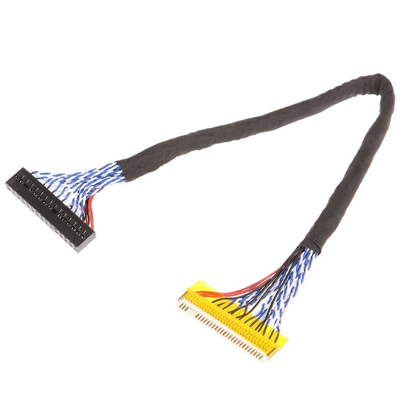
1) Buy a proper cable: FIX-30P-S6 , it will work as intended.
If you have a high-res panel, make sure the cable in the picture has as many wires as the cable in the store listing - a cable with only half of the blue&white wires would be called FIX-30P-D6, and while it might work for you if your display only uses half of the lanes (i.e. a 1280x800 display or a 1366x768 display), it won't work for higher-res displays.
For some reason, some sellers sell FIX-30P-S6 cables with "FIX-30P-D6" in the listing name - and vice-versa. In that case, you should go by whether there's "dual" mentioned in the listing name *and* on whether the photo is correct - if there's both a "dual" in the listing name and a photo shows a dual LVDS cable as pictured above, it should be safe to buy - or refund, in case that fails =D
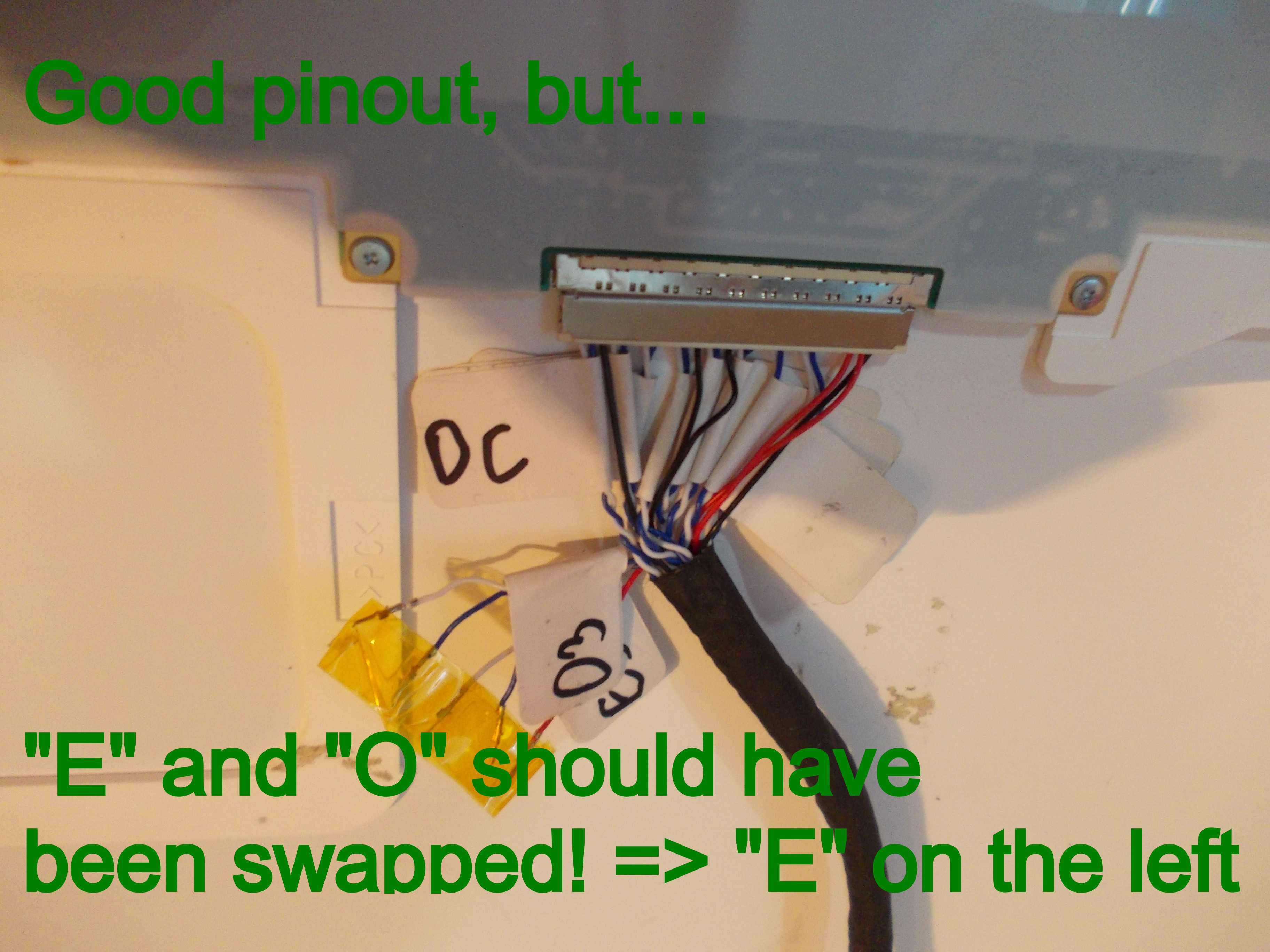
What if you can't easily buy a replacement cable, though? Maybe you have budget constraints, maybe you need it urgently, or maybe you're miffed - after all, you already have a perfectly good cable, just that it's miswired!.
---------- more ----------
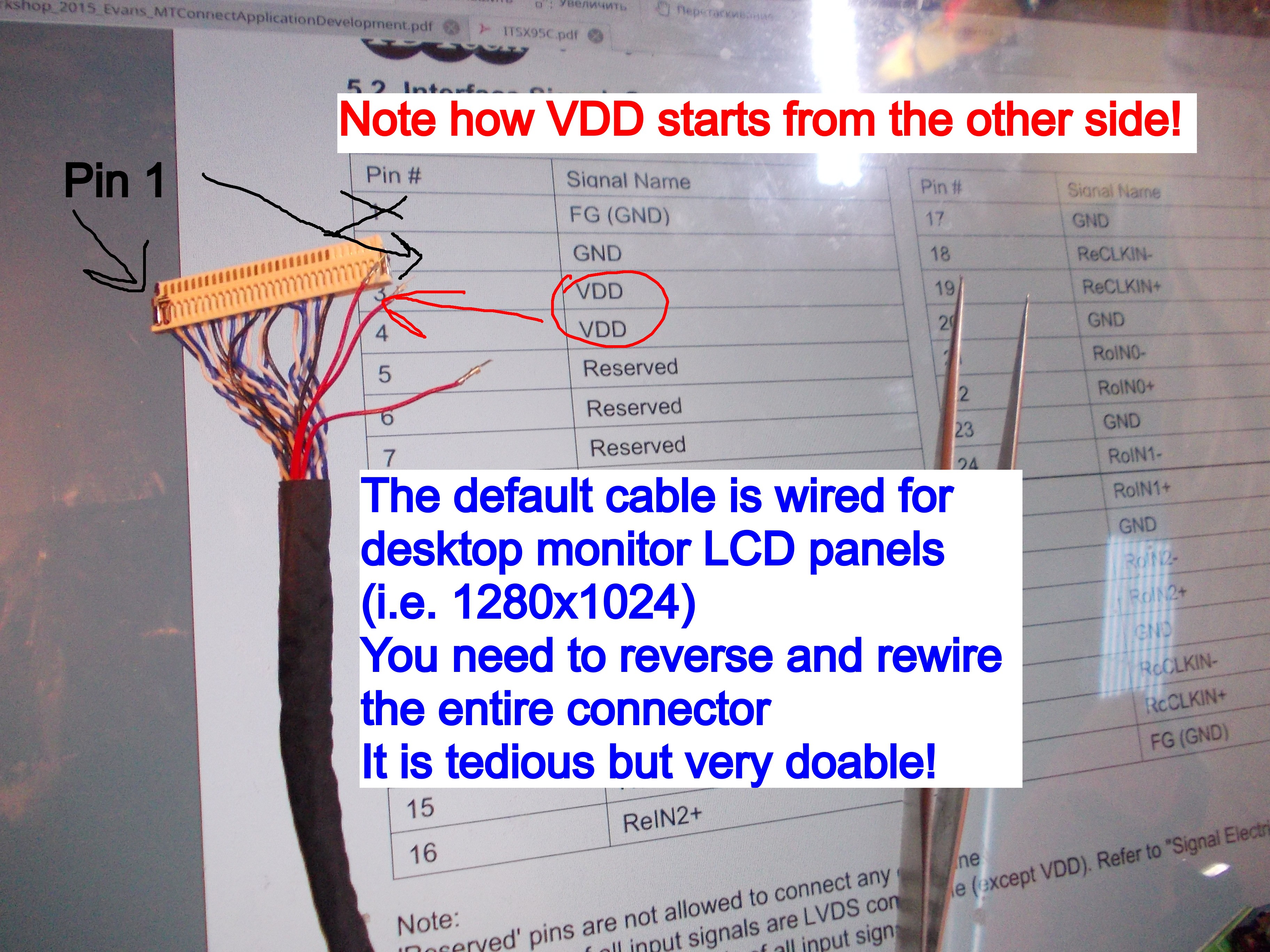
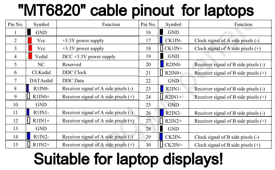
Here's the original cable pinout that you will get from the shop:
Here's *the* pinout that, chances are, you want:
The above picture shows wire colors and exactly which pins I suggest you populate which way, as well as reminds you of the LVDS wire polarity colors. "R1*" wires should be "O" (LVDS Odd) and "R2" wires should be "E" (LVDS Even). Don't forget - white wires are + and blue wires are - !
"E3" and "O3" wires will be left hanging - that is perfectly fine. Wrap them in tape or heatshrink individually - don't let them short out among themselves or inside the case!
Not all the grounds are needed, but it is good practice to have at least one ground wire next to panel power (where pinout demands it), as well as to surround your LVDS clocks with ground wires so that they don't impact neighbouring signals - the default HX6810 cable has just enough ground wires to do that perfectly!
-There's three VCC (red) cables in the pinout but you only show two inserted on the picture! What do I do with the third one?
As the pinout diagram above suggests, put the third wire into 4th pin position - the one where the EDID VCC is. It won't help there, but it won't interfere there either, and it's one less wire hanging unconnected, which is good. My pictures were taken before I figured this out.
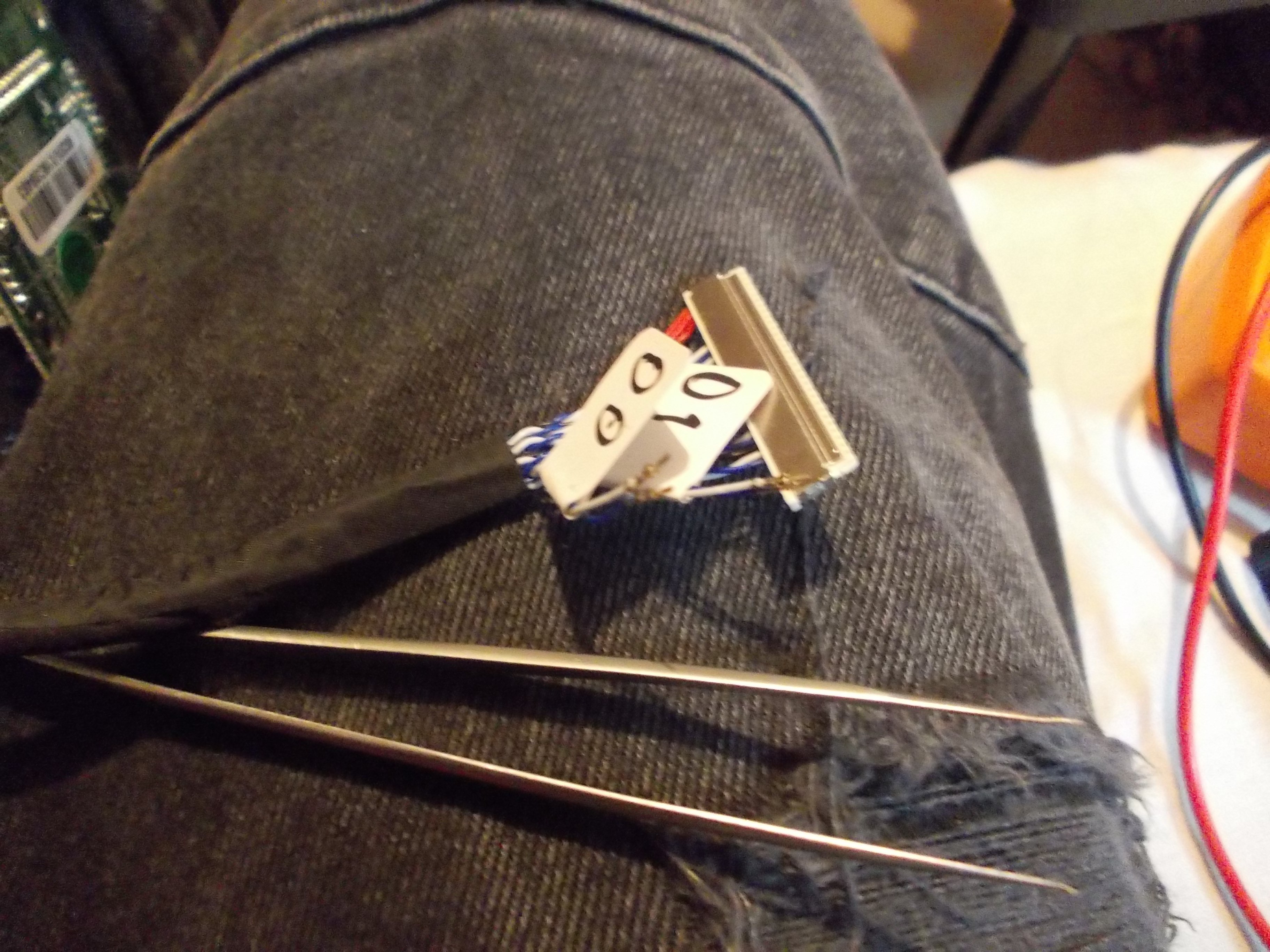
I started my first cable conversion for HX6810 by removing wires and marking them pair-by-pair:
Not shown, but an xacto knife works best for gently bending the pin latches when removing the wires, tweezers, even sharp ones, don't work all that well.
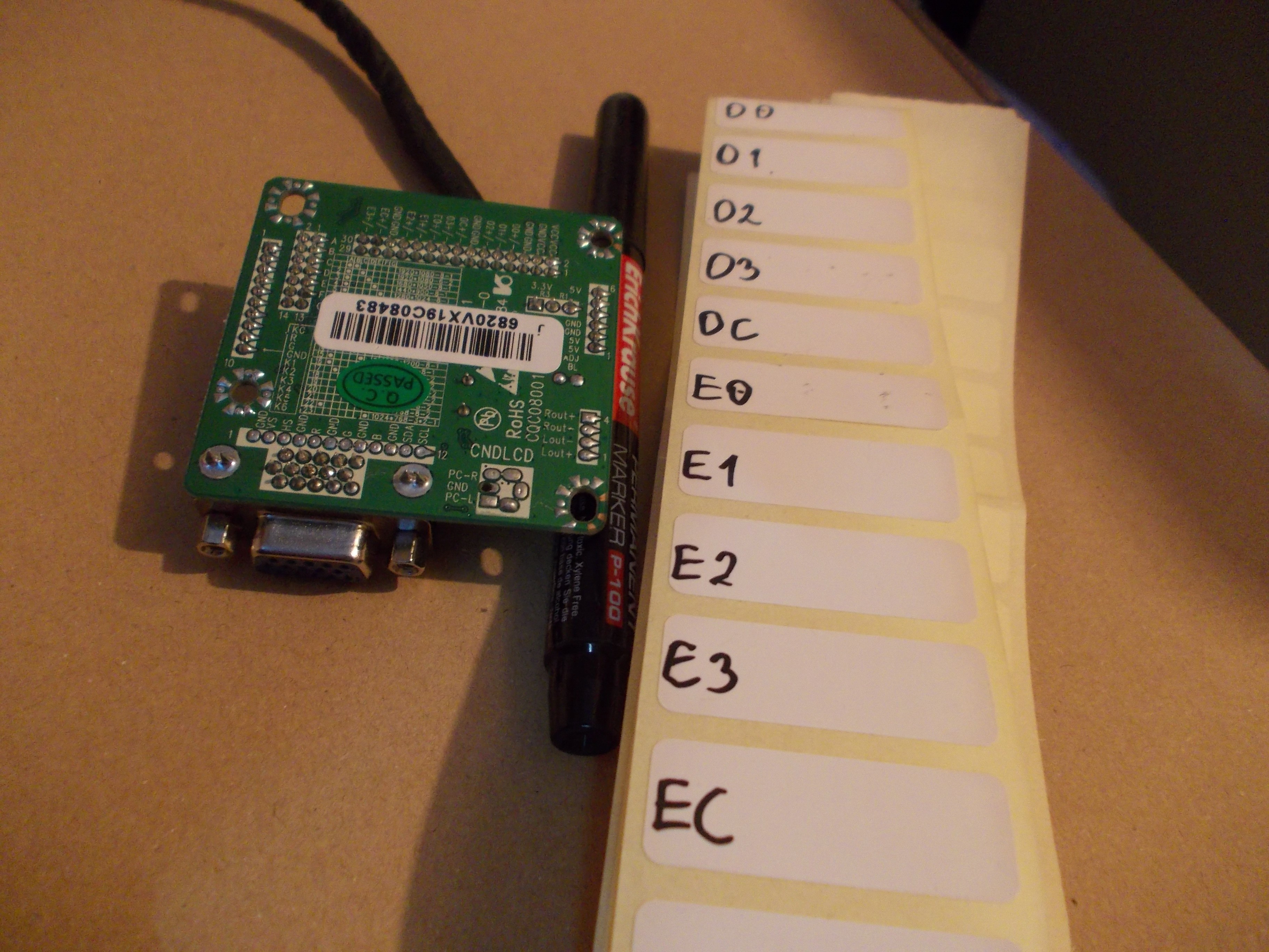
I had some labels prepared, of course:
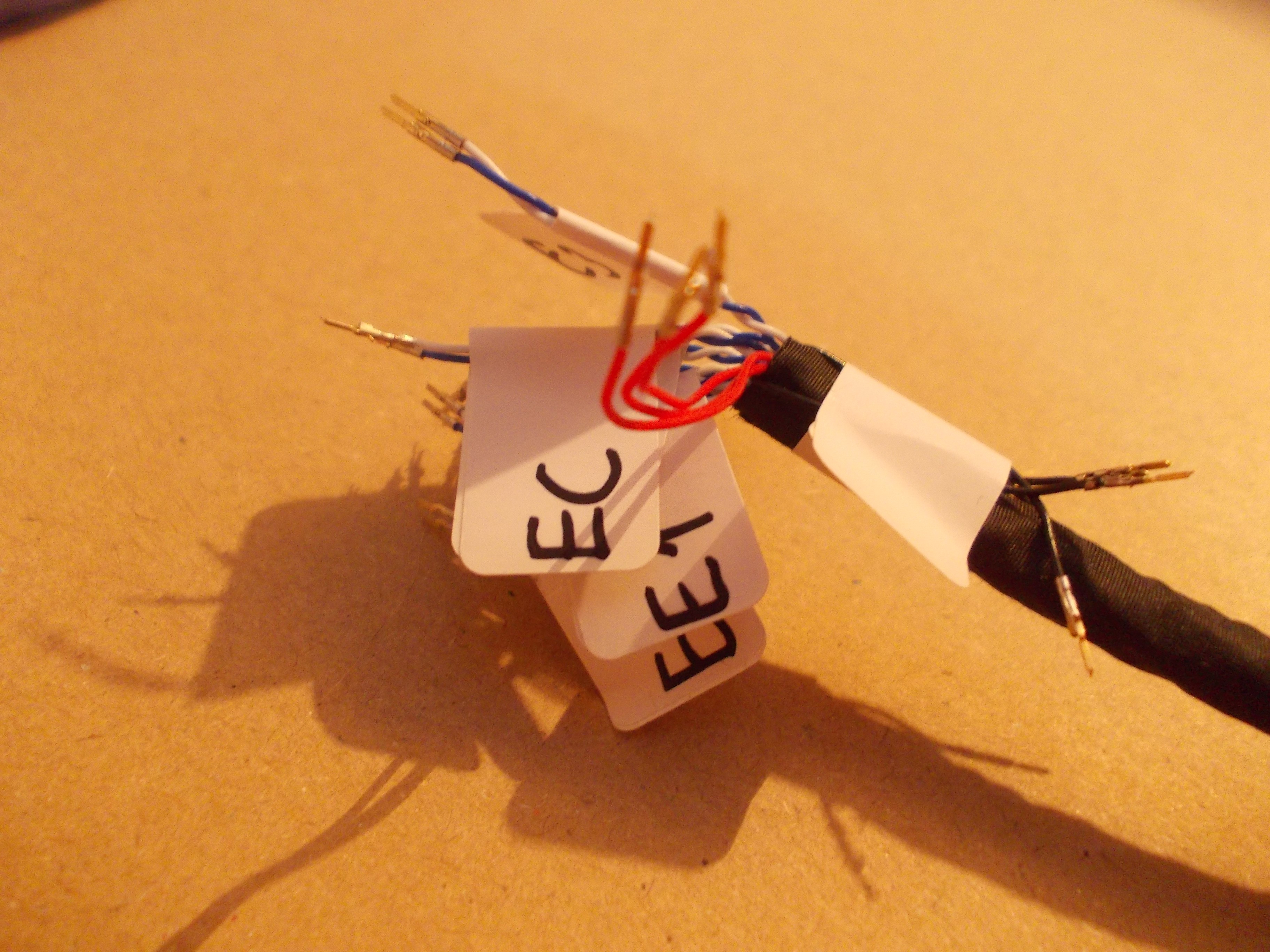
All removed and marked (except VCC and GND, these are obvious by their color)
Then, I reinserted them into the shell following the proper pinout.
What does it look like with swapped wires?
After swapping E and O pairs, it started working great! I don't have a picture to show for it, just trust me ;-P
It was much easier to swap E and O pairs on the MT6820 board side. In fact, I've split the 2mm connector into 2x3, 2x6 and 2x6 portions just so I could do that easily! You can do that with some spare 2mm cable housings, filed down if needed - I will be selling small conversion kits for the experimenters among us, being able to swap&disconnect pairs actually does help sometimes!
I hear things about different panels treating "even" and "odd" differently, so what is marked as "odd" in the panel datasheet might very well be "even" when it comes to the MT6820 board output. In case that happens to you, be prepared to rewire your cable - sadly, AFAIK that's the only solution.
My next conversion, I did without marking anything - by having the LVDS cable inserted into the "MT6820" board and beeping the LVDS-side connector against the "MT6820" pinout markings on the PCB, using a multimeter. You can likely do it the same way, too - it's just a bit more daring =)
 Arya
Arya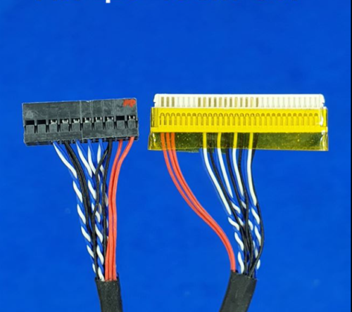


 Oh, a very specific set of 18.5" displays, it seems. I sure hope people don't buy this cable on accident!
 I guess they wisened up? Hopefully, that is the case.
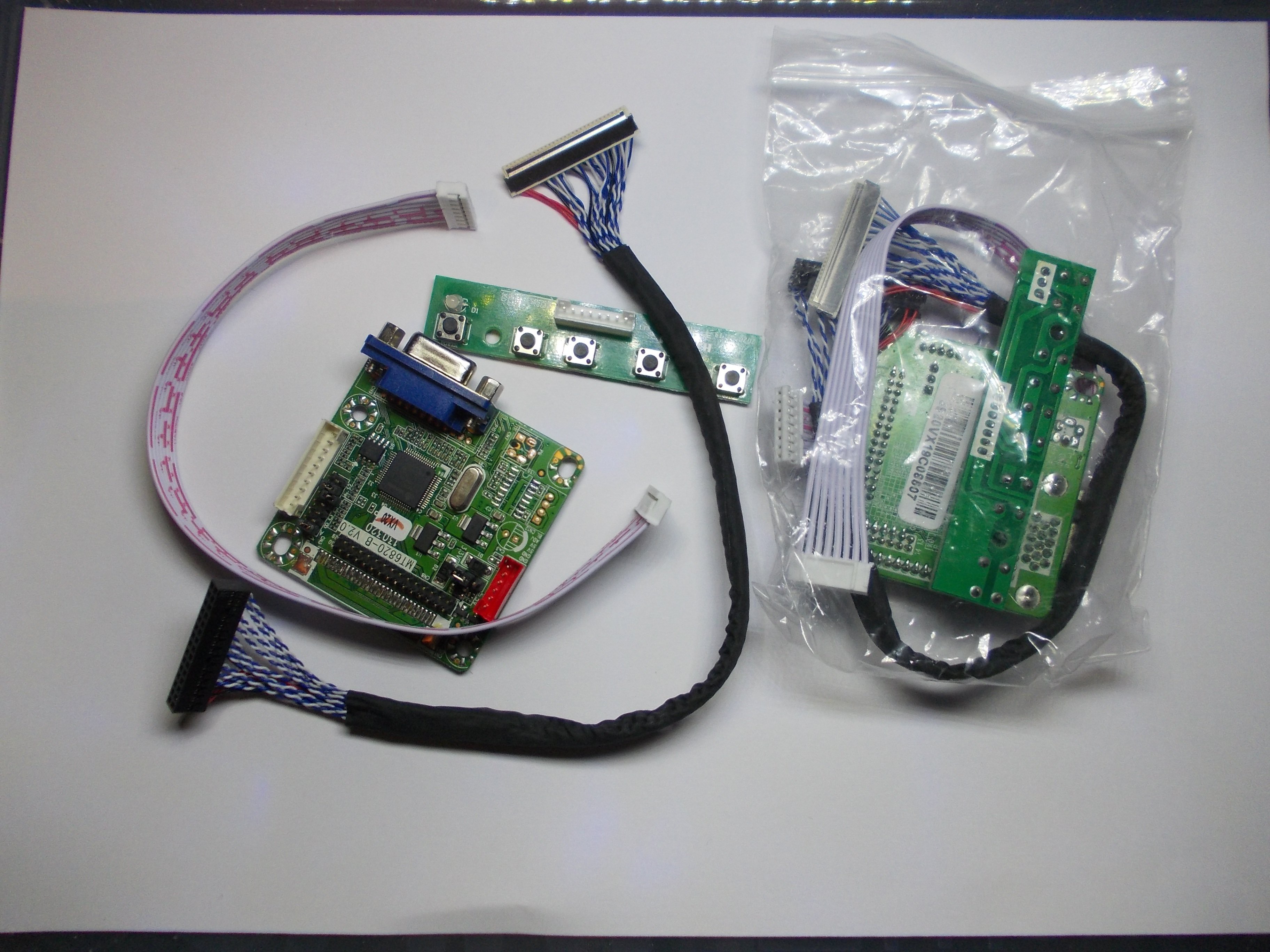
 Onboard, 2 voltages are created using two linear regulators - 3.3V and 1.8V. 3.3V from the regulator seems to go to the controller and not the panel.
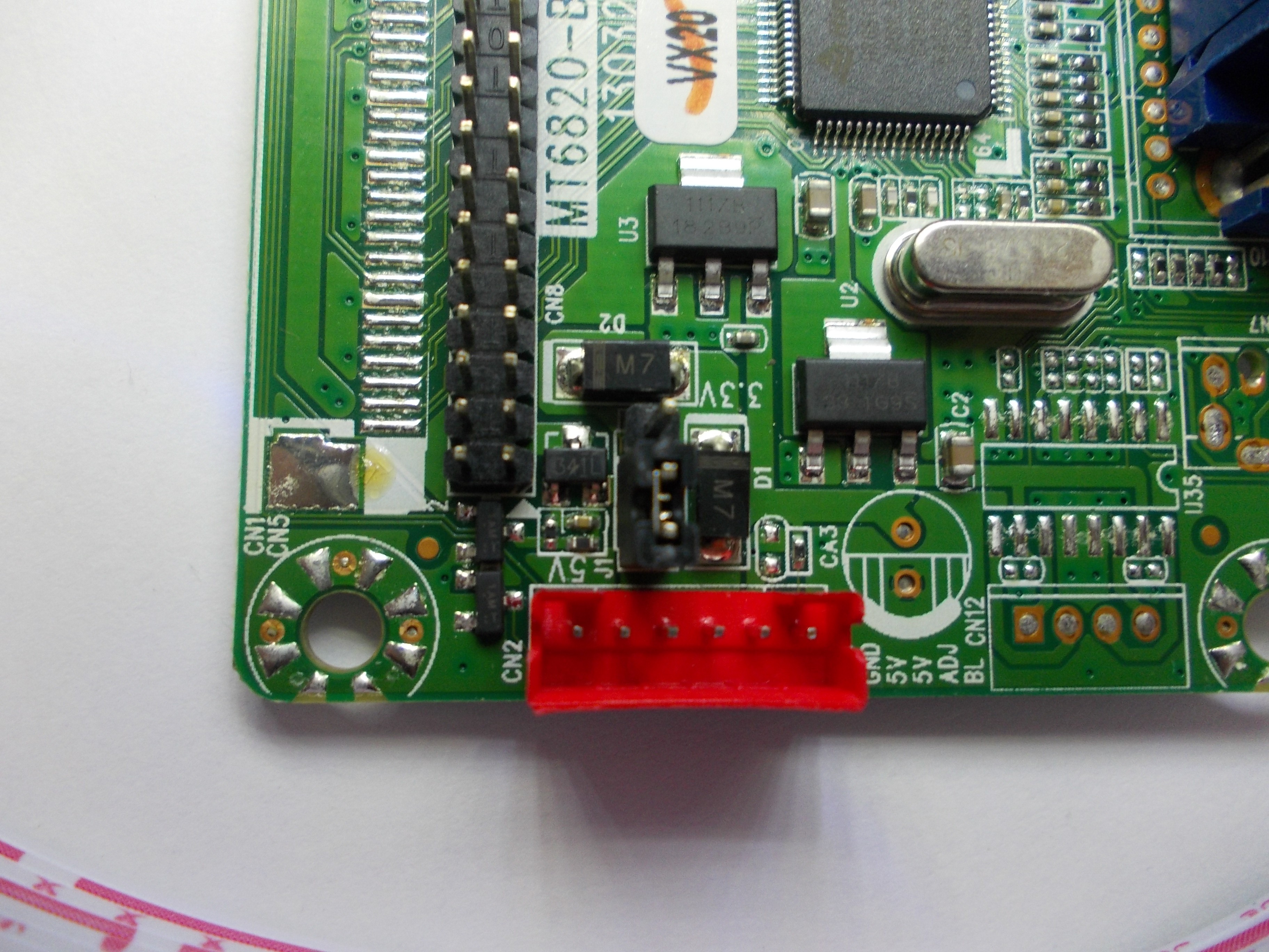
 There's also an EDID stored in a separate location, perhaps a "default" one? That makes for 15 different EDIDs.
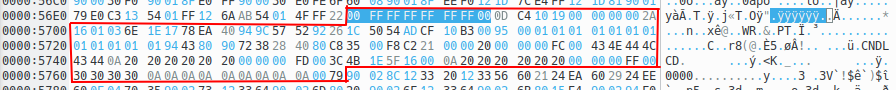 OSD strings are stored as null-terminated strings - so, if needed, one can change the OSD strings easily ;-P


 [TODO: insert desktop LCD panel connector photo]