Utilizing sensor controller:
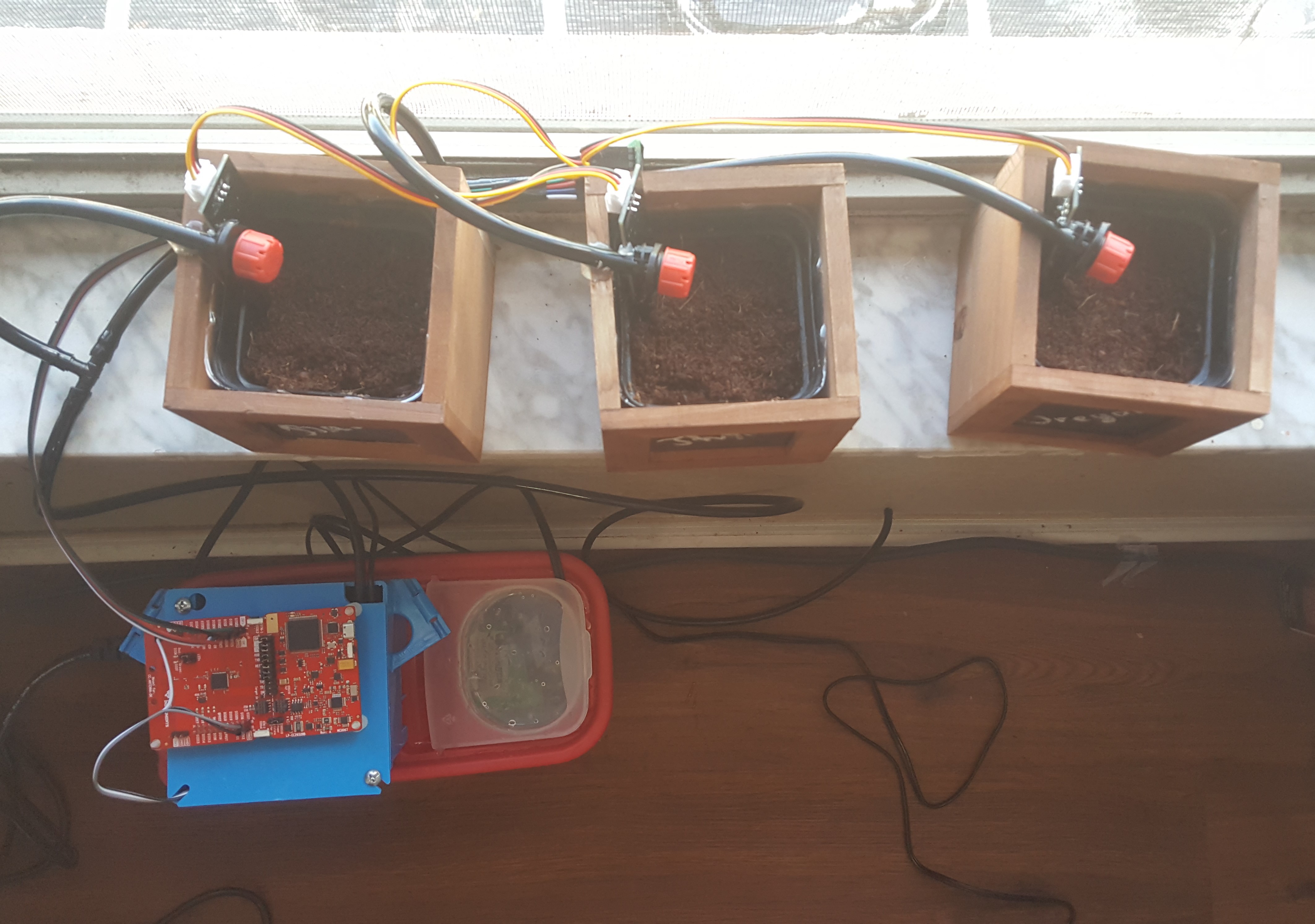
One of the biggest advantages of using Texas Instruments MCU (I'm using CC2652 evaluation board) is its sensor controller. The sensor controller is a built-in CPU that can be used to read sensor data (ranging from digital and analog pins to communication interfaces like I2C and SPI). It can capture the data and store it in a structure that the main CPU can access easily. Most importantly, the sensor controller deals with event handlers, which have much lower priority than interrupts and ISR, allowing it to run in the background with little interference.
Implementing the sensor controller will free up the main CPU, thus allowing the main CPU to perform more tasks. As I want to keep its power consumption to a minimum, I program the logic such that it relies only on event listeners, which looks something like this (EH stands for event handler):
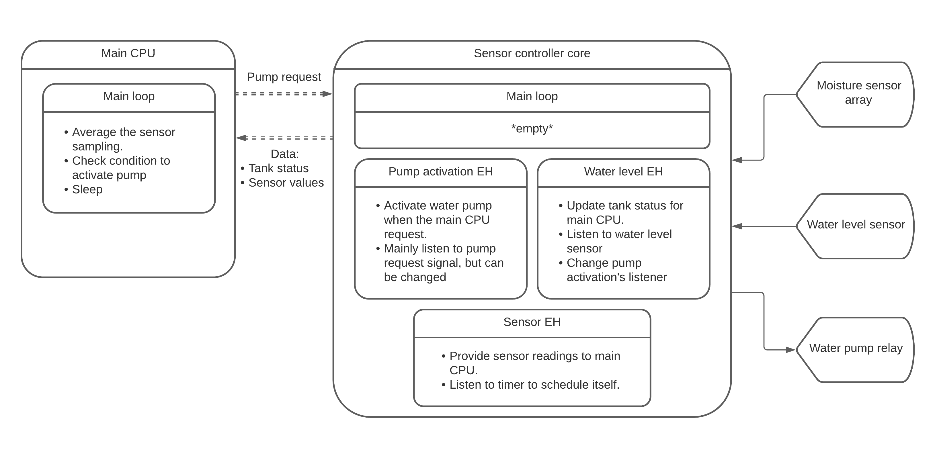
As you can see, for the minimum implementation, the main CPU doesn't need to do a lot of work, most of the operations are handled in the sensor controller. In the future, I look forward to implementing the Zigbee stack into the main CPU to make this an operational Zigbee device. It can then be a part of a smart home IoT system.
Water pump controller:
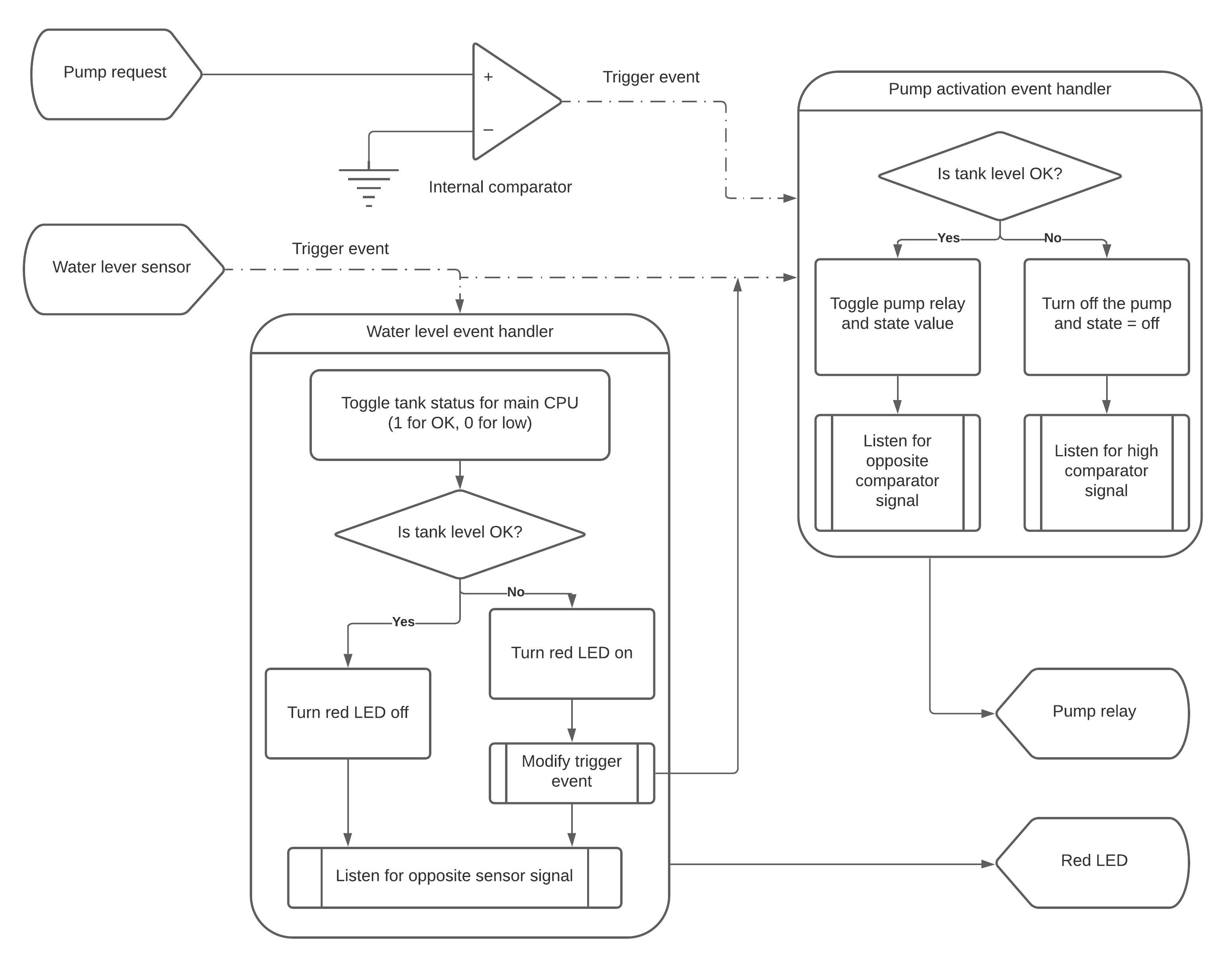
The logic is quite simple, there's 2 event handler, one to monitor the water level, one to control the water pump relay. As there's not a real way for the main CPU to directly interact and trigger an event, an internal comparator (known as COMPA by sensor controller) is used to generate the trigger signal. Pump activation EH will listen to the comparator output and control the pump relay. In the case where the water level EH detects a low signal (the sensor operates like a pull-up button), it will cancel the current pump activation EH trigger and make it listen to a low signal from the water level instead.
Sensor sampling:
The last event listener will handle the sensors. In practical application, an analog sensor needs to sample multiple times as each of the samples can vary greatly. Therefore, a sensor needs to sample multiple times so that the compute the average is more accurate. The sensor EH uses the timer to trigger itself and read the sensors at the correct timing. In this block diagram, each sampling value is separated by 1ms.
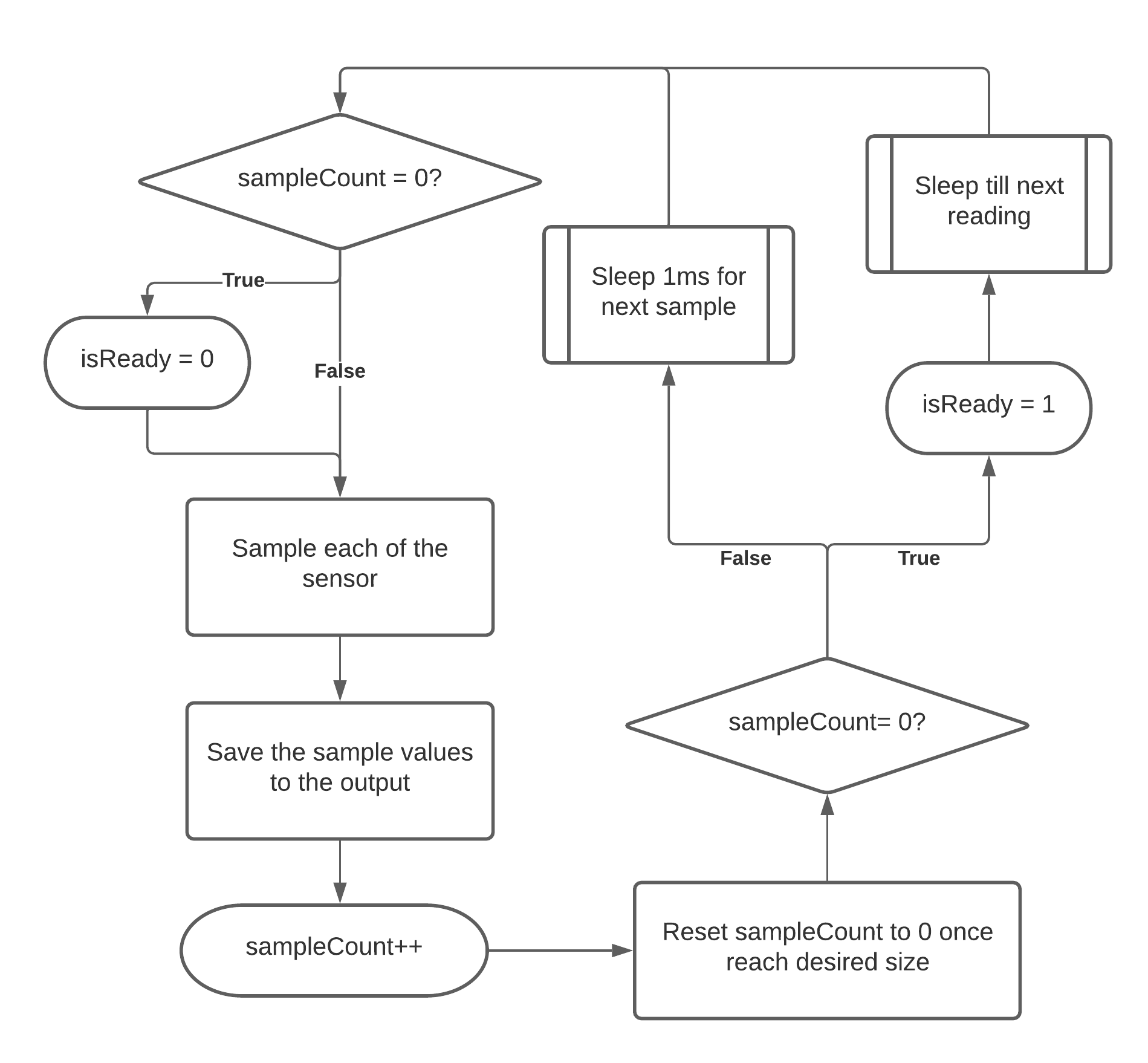
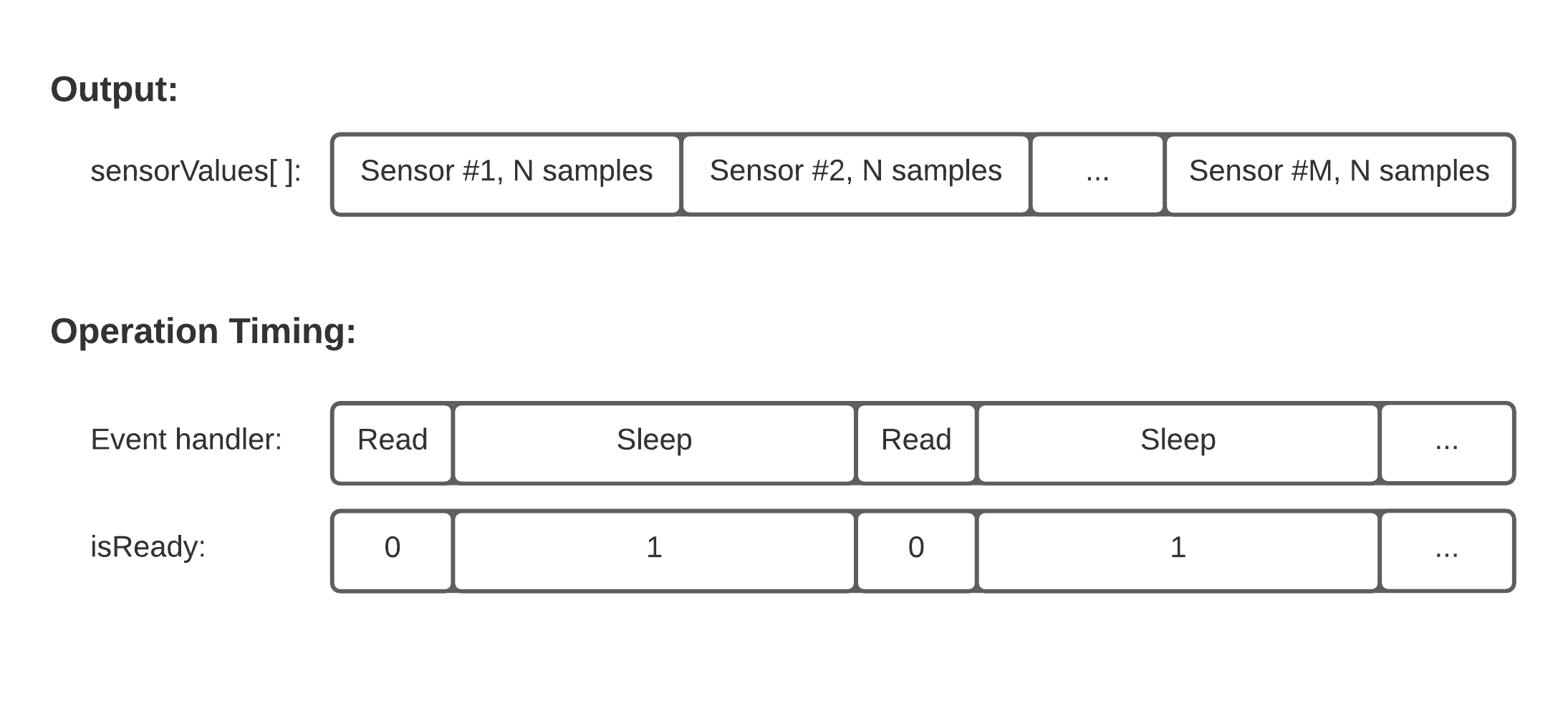
In addition to the sampling values, this EH also provides the value isReady. This lets the main CPU knows if the EH is in the process of reading and editing the sensor values or not. The main CPU can wait with while( isReady == 0 ) { } for the EH to finish. The output array structure of this EH and its timing is as follows:
The difference between single reading and multiple samples per reading is seen as follows: the values are more stable in comparison.

Expanding the program (WIP)
Thanks to RTOS, a system can run multiple tasks. One important thing to notice: only 1 task can be operational at any given time. Most of the time a task is blocked by semaphore pend, event pend, message pend, or sleep. Once a task unblocked, it'll wait for its turn to run by the priority system, ensuring thread safety. One task can be pause mid-operation if another task with higher priority is unblocked, this is the key to a responsive and real-time application.
The main CPU will have global variables so that the tasks can share the resource. In this application, most of the resources are read-only and modified very rarely, so the tasks don't need to be strictly synchronized. The prototype will now look as follows:
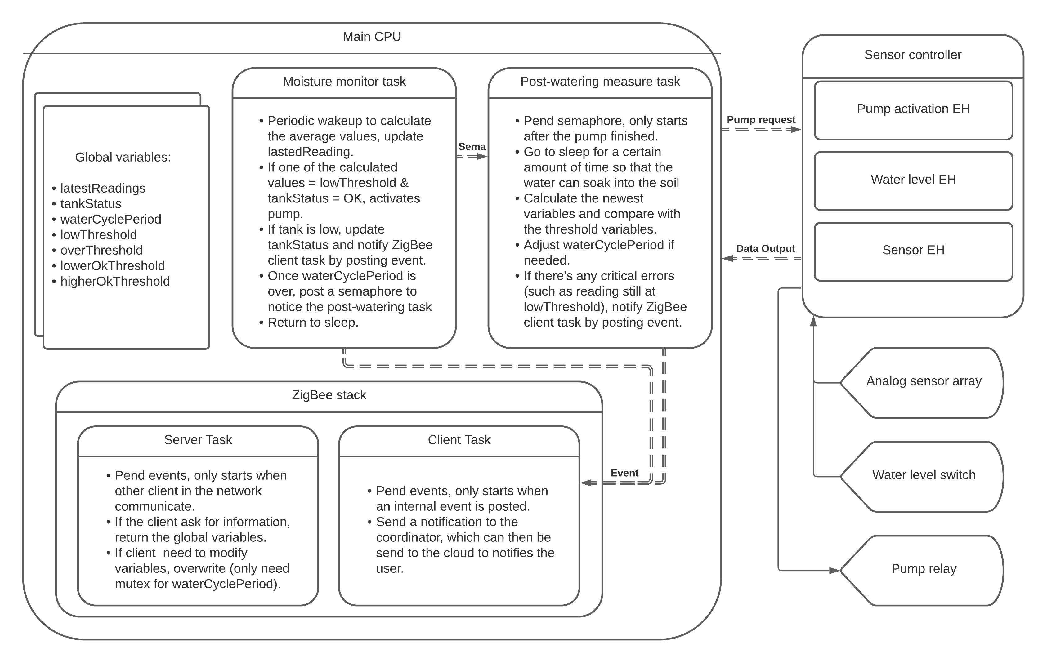
Let's just appreciate how modular the entire system is. Each task can be individually modified without any worries of affecting another. The Zigbee client task can listen to multiple events from any task. To separate each event from another, we can use bit masking technique (where each bit corresponds to an event). If the system is connected to the cloud, the events can be notified to the users.
The next step is to implement the...
Read more » Vinh Tran
 mircemk
 Rohan Menon