 Josh Joy
-
1Introduction
Note that your exercise bike might be completely different from mine and the procedure might be a bit different but this tutorial should give you a rough idea on how it’s done. These instructions assume that you have basic knowledge on Arduino and electronics.
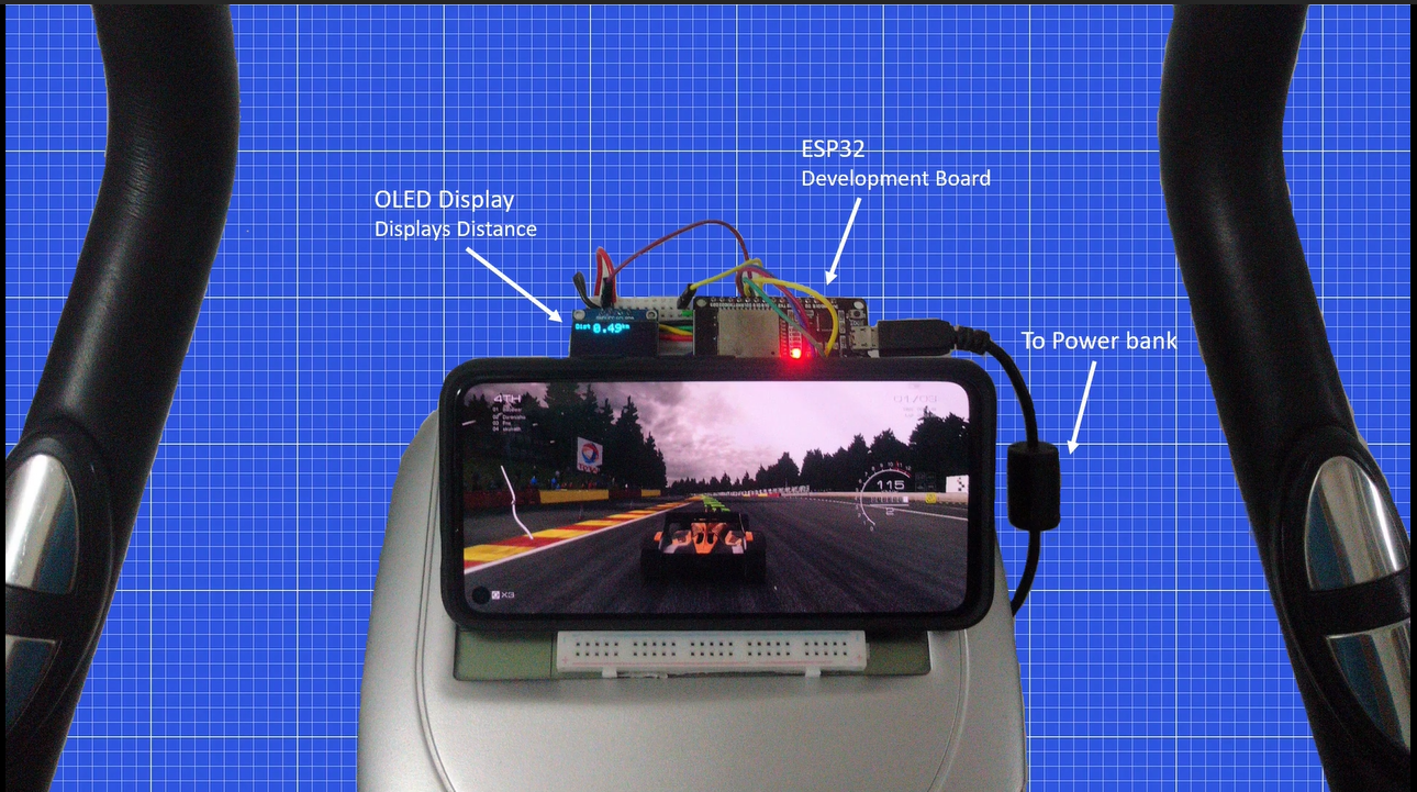
Here’s a close look of the exercise bike.
I have used the ESP32 microcontroller as it comes with Bluetooth and I wanted to turn my bike into a wireless gamepad,
it is powered using a power bank and there’s an OLED display to show the distance pedalled as the built-in display isn’t working.
-
2Using the exercise bike pedal as an input
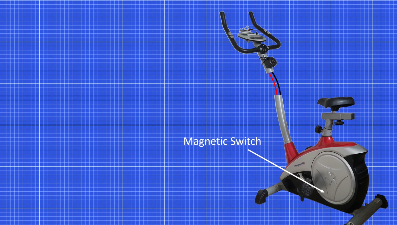
The first thing I wanted to do was to figure out how fast I was pedalling. So I took apart the bike’s display and found that there were 2 wires connecting the base of the bike to the bike’s display circuit.
The wire’s are probably connected to a magnetic switch.
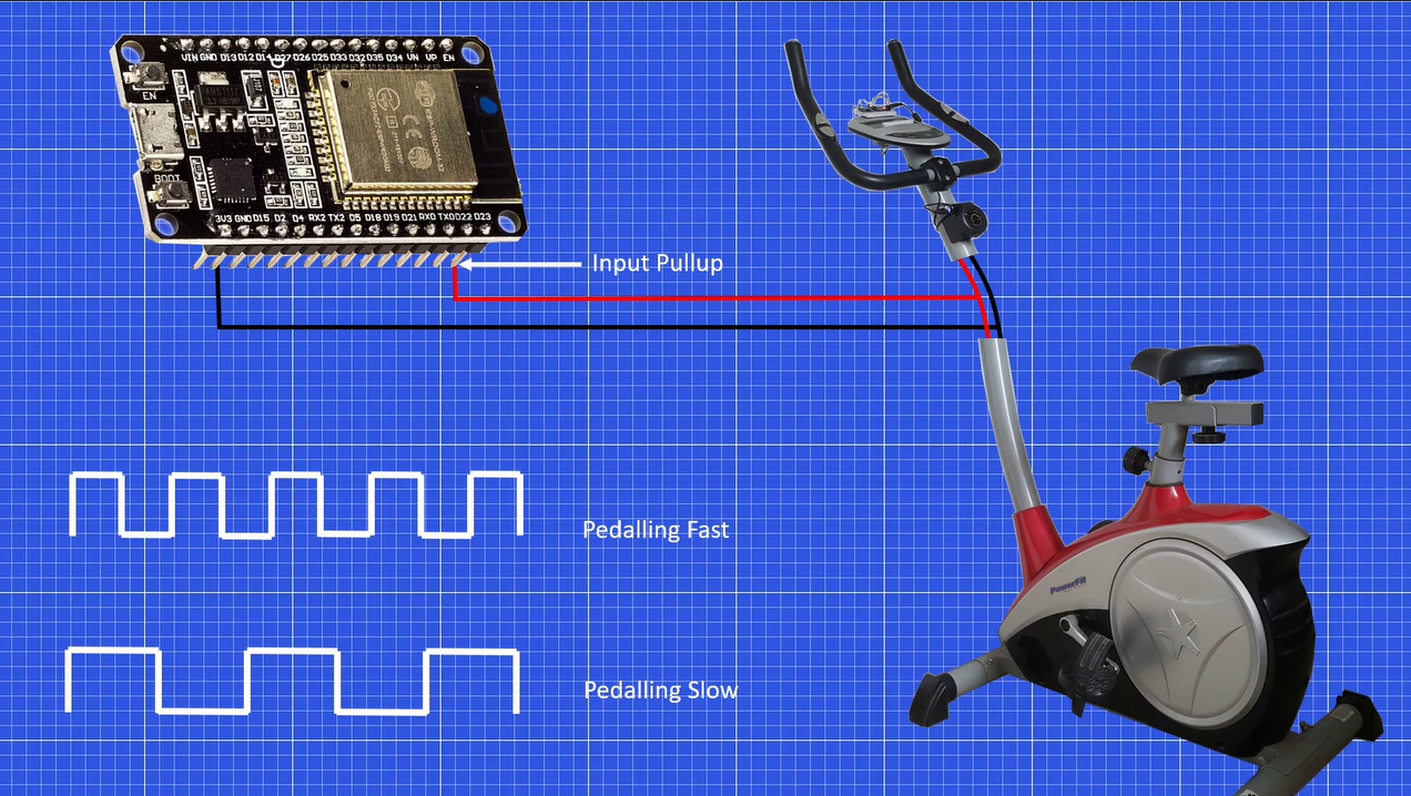
I connected these two wires parallel to the ESP32 assuming one was gnd and the other having some type of signal.
I then wrote a program in Arduino IDE to monitor the signal pin and got a square wave when pedaling. You can find the code here: https://ivthdimension.wordpress.com/portfolio/exercise-bike-hacked-into-a-wireless-gamepad/
The faster I pedaled the more pulses I got, note that I had to pull the input HIGH to get a square wave.
Thus we can figure out how fast we pedaled based on the number of pulses obtained in a second.
The distance can be computed by counting the total pulses.
Most exercise bike’s give an approximate distance value, as distance travelled on a bike is based on the bike’s wheel diameter and we do not have a wheel. You can find the code here: https://ivthdimension.wordpress.com/portfolio/exercise-bike-hacked-into-a-wireless-gamepad/
-
3Using the exercise bike touch pad / buttons as inputs
Now we need some buttons to interact with the game.
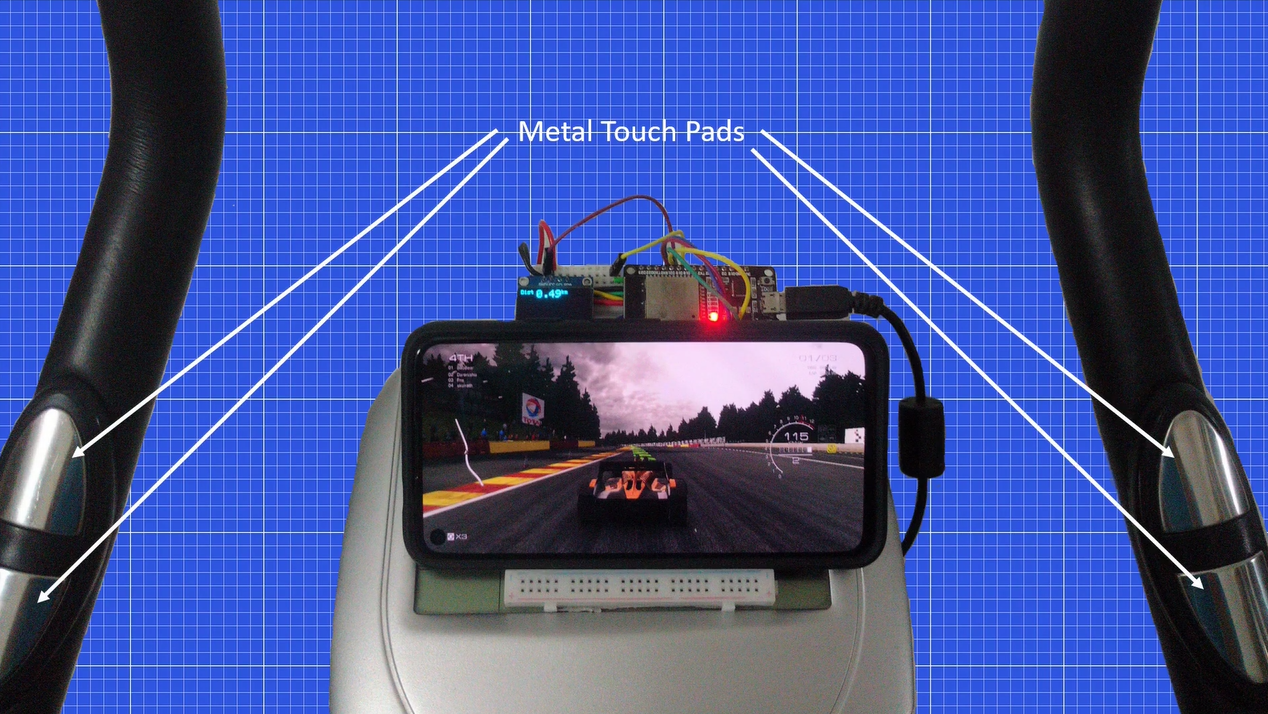
My exercise bike came with these metal touch pads, they were originally used for the heart rate sensor.
But as the built in display wasn’t working, it isn’t possible to see the heart rate
and so I decided to use them as gamepad buttons.
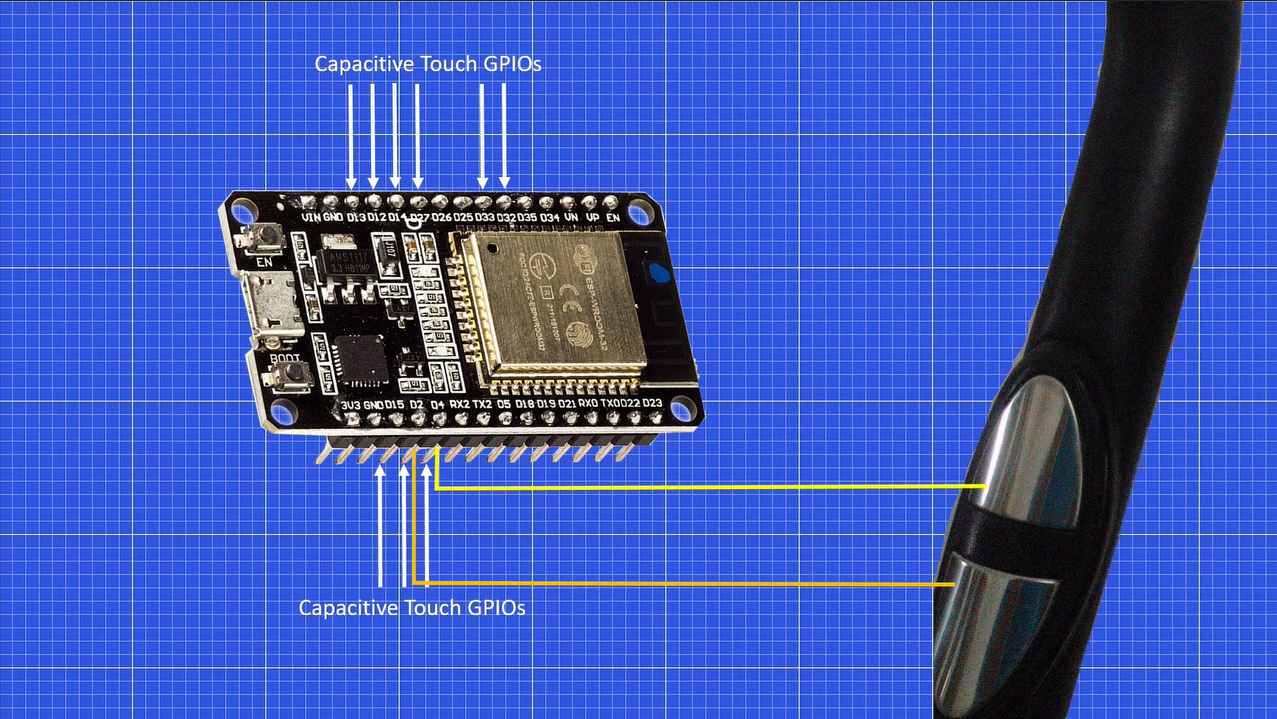
The ESP32 comes with capacitive touch sensitive GPIO pins, thus we could just hook up the metal touch pad to the specified GPIO pins and monitor if the touch pad is being touched or not.
But unfortunately when I used long parallel wires connecting the Touch pads to the GPIOs, I managed to get accidental presses, probably due to parasitic Capacitance.
Touching one pad would result in two GPIO pins going high.
Although sometimes this did work fine, I couldn’t get it work all the time and there were far too many accidental button presses.
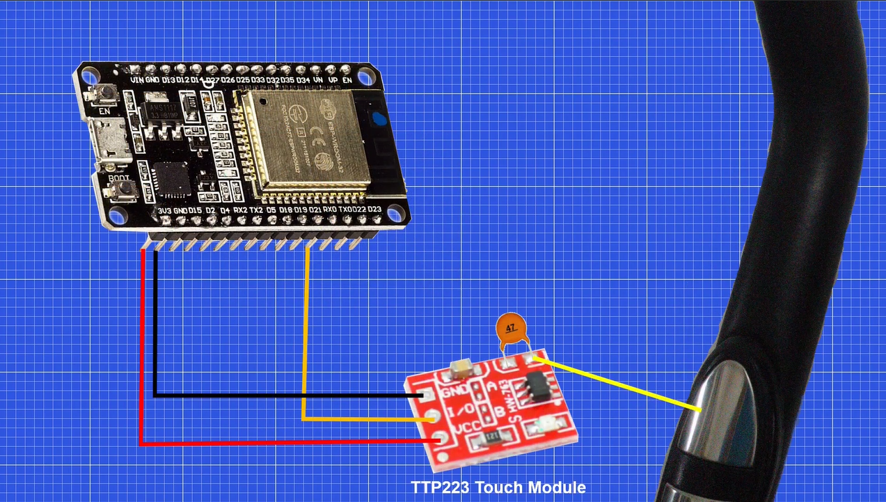
So I decided to use these TTP233 touch modules, although this made the wiring more complex it worked well.
Note that I had to use a ceramic capacitor to adjust the touch sensitivity.
You can find the code here: https://ivthdimension.wordpress.com/portfolio/exercise-bike-hacked-into-a-wireless-gamepad/
-
4Turn the ESP32 into a bluetooth Gamepad
Now we need the ESP32 to be recognized as a Bluetooth gamepad,
with the pedal and touchpads as inputs.
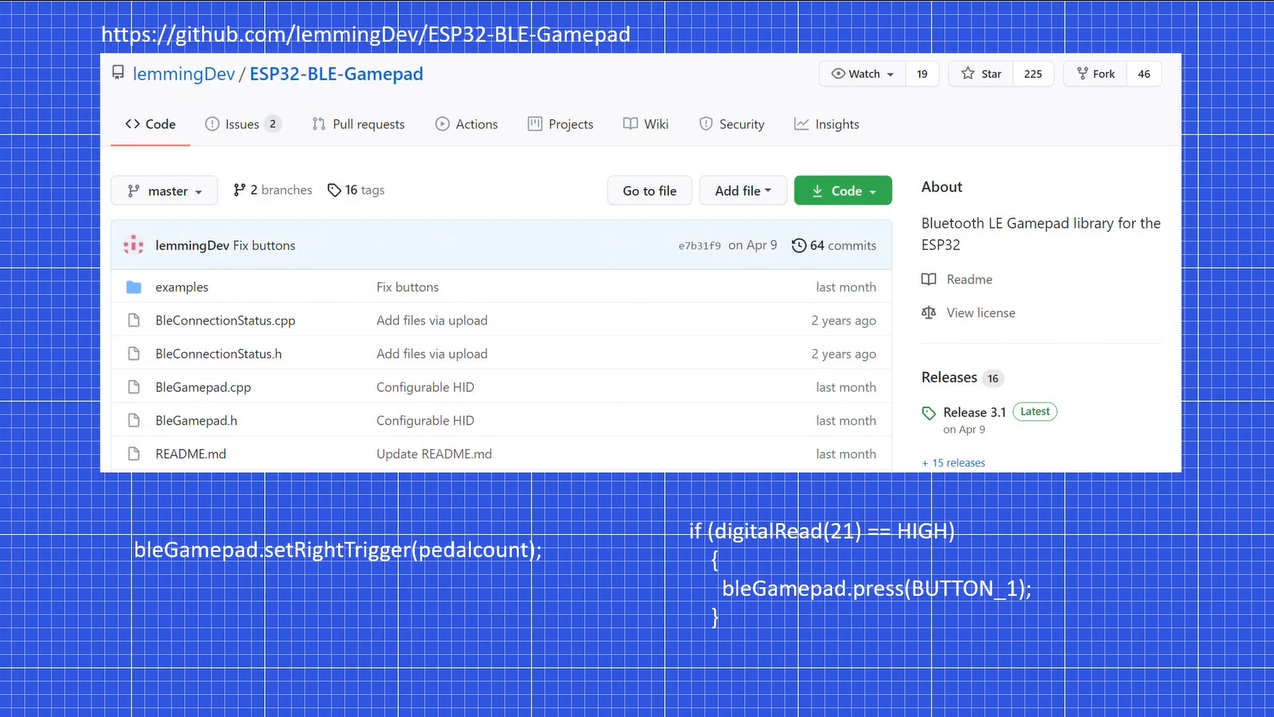
There’s an ESP32 BLE gamepad library on github by the user lemmingDev, which lets us easily do this: https://github.com/lemmingDev/ESP32-BLE-Gamepad
I had some issues with the Bluetooth not pairing properly, to solve this I would suggest you to keep your code as similar to the example code as possible.
In most racing games the gamepad right trigger acts as the accelerator pedal, thus we could use the pedal pulse count as an argument for the setRighttrigger function.
In reality the code isn’t this simple you would have to map the pedal count range to the Righttrigger range, this is done by experimenting with different values.
A gamepad button can be pressed if the touchpad is touched.
For the complete program do have a look at my Github: https://github.com/joshjomer/Exercisebike-to-a-Wireless-Gamepad-using-ESP32
-
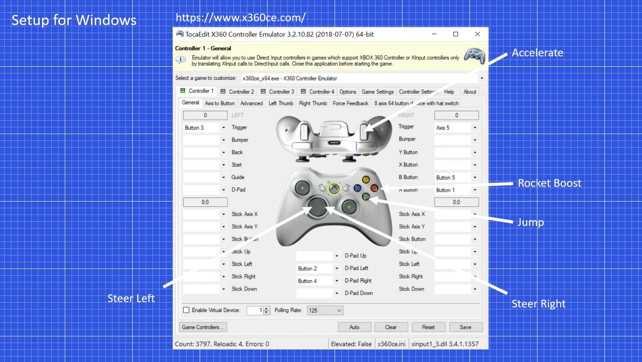
5Setting up for PC
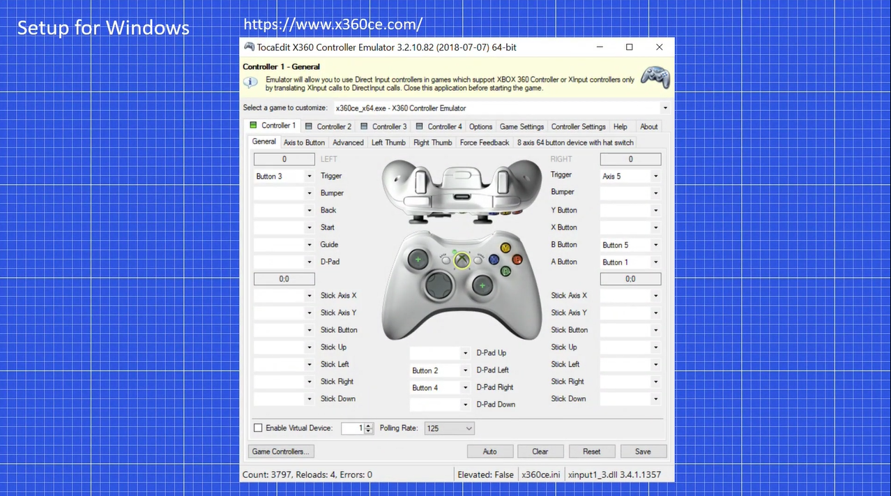
After pairing the esp32 with the computer, the esp32 is recognized as a generic gamepad.
But most PC games need the gamepad to be recognized as an xbox360 controller, so we need to use the x360 controller emulator. https://www.x360ce.com/
For instructions on how to use x360ce: https://www.x360ce.com/#Help
I have configured this for the game rocket league.
Since we have only four touch pads, I mapped the four touch pads to the most essential xbox360 buttons to play the game.
Which were to steer left, right, jump and rocket boost.
The right trigger is selected as axis 5 which has the output of the set right trigger function.
The x360 emulator lets us combine two controllers, thus we can combine a regular gamepad with our exercise bike to have more buttons.
-
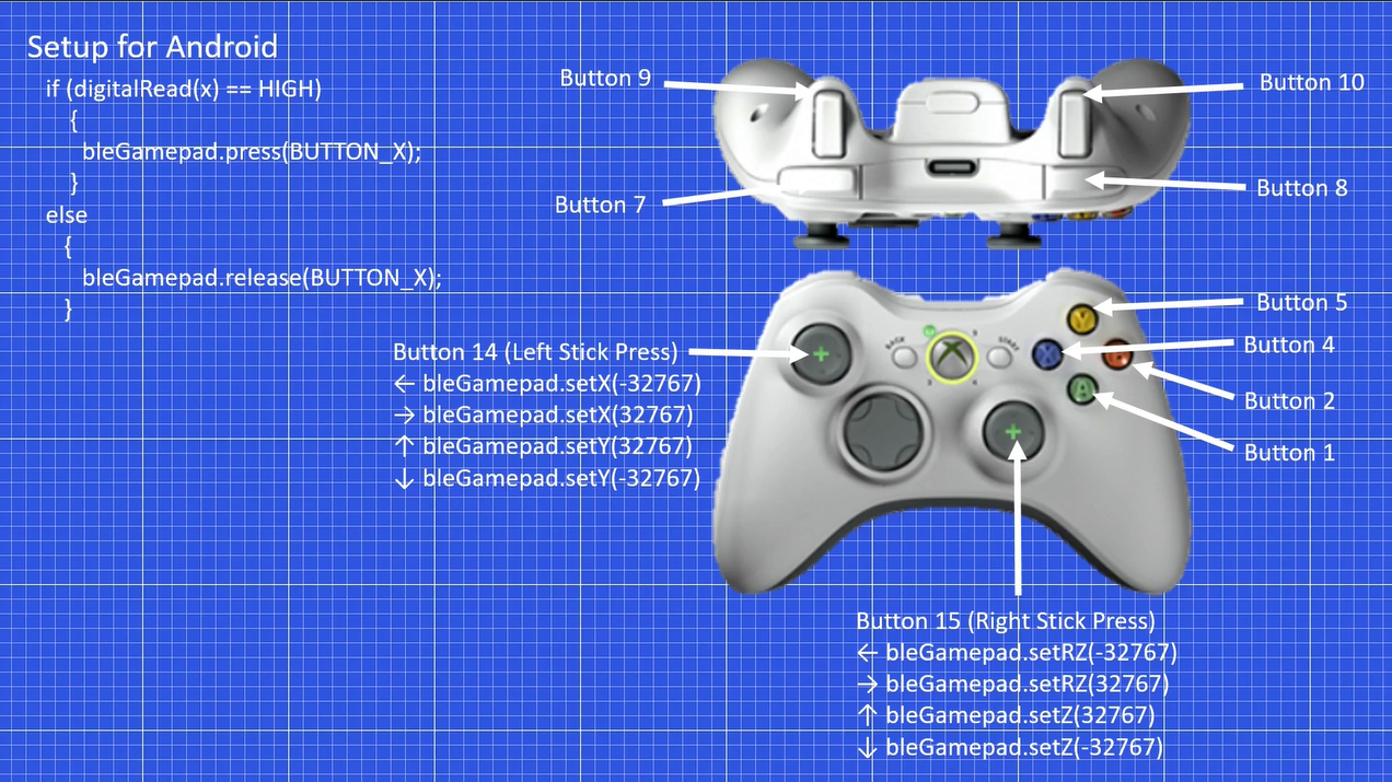
6Setting up for Android
Not all android games do support gamepads, but for the ones that do, the buttons can be configured according this image.
So button 1 in the program becomes button A of the controller.
Depending on the game, the buttons can be selected appropriately.
If you would like to see a detailed explanation of the programming done, have a look at my blog post: https://ivthdimension.wordpress.com/portfolio/exercise-bike-hacked-into-a-wireless-gamepad/
You can find the code here: https://github.com/joshjomer/Exercisebike-to-a-Wireless-Gamepad-using-ESP32
-
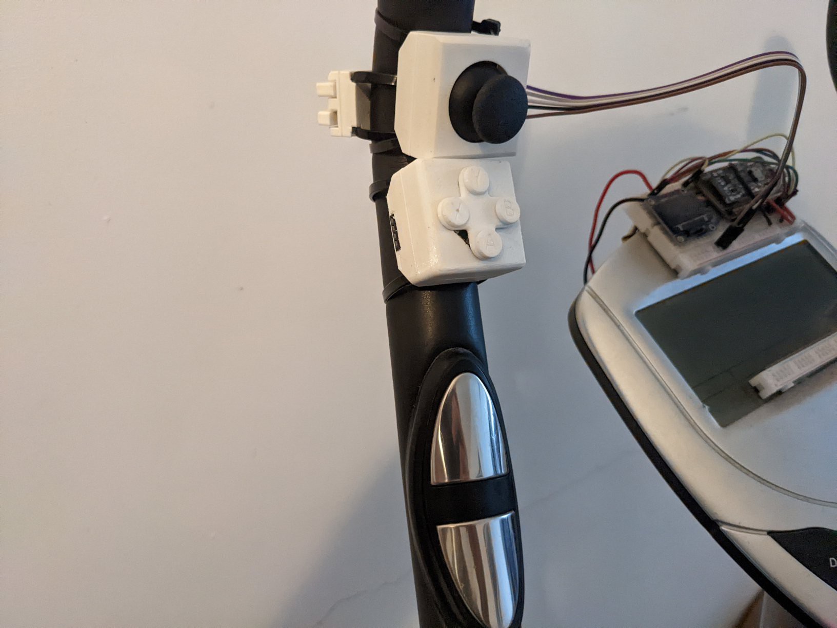
7Adding Buttons (Optional)
In case your exercise bike does not have sufficient buttons/touch pads to interact with the game, you can add buttons. In the below image I have added a joystick, a d-pad that also acts as XYAB buttons, and also LB and LT buttons which are housed in a 3d printed enclosure. The 3d printed enclosure has slots through which zip ties can be passed and thus these buttons can easily be fastened to the exercise bike handles. I hope to use these modular gamepad inputs for a future project that could work with treadmills and other equipment. I have uploaded the STL files in the files section, note that the design is still a work in progress. I have also attached the freecad files so you can edit them.
![]()
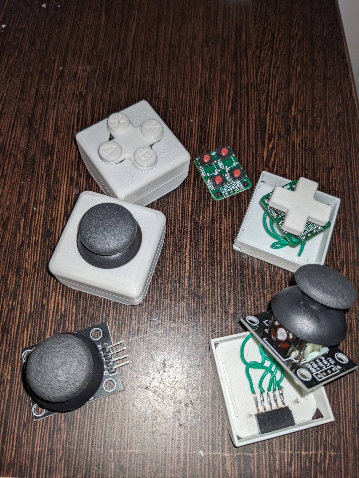
I have used the following Joystick and buttons:
https://robu.in/product/joystick-module-ps2-breakout-sensor/
https://robu.in/product/2-x-2-matrix-4-push-button-keyboard-module/
Note that the buttons are a little bit too hard to press, I hope to replace these later. I have soldered header pins to position pins in the right area for the cad model.
![]()
Exercise Bike to a Wireless Gamepad [ESP32]
Hacked an old exercise bike into a wireless gamepad using the ESP32 Microcontroller.
Discussions
Become a Hackaday.io Member
Create an account to leave a comment. Already have an account? Log In.