seasleyece
-
PWBs have arrived!!!!
05/24/2021 at 23:12 • 0 commentsAfter a few weeks the PWBs have arrived!!!
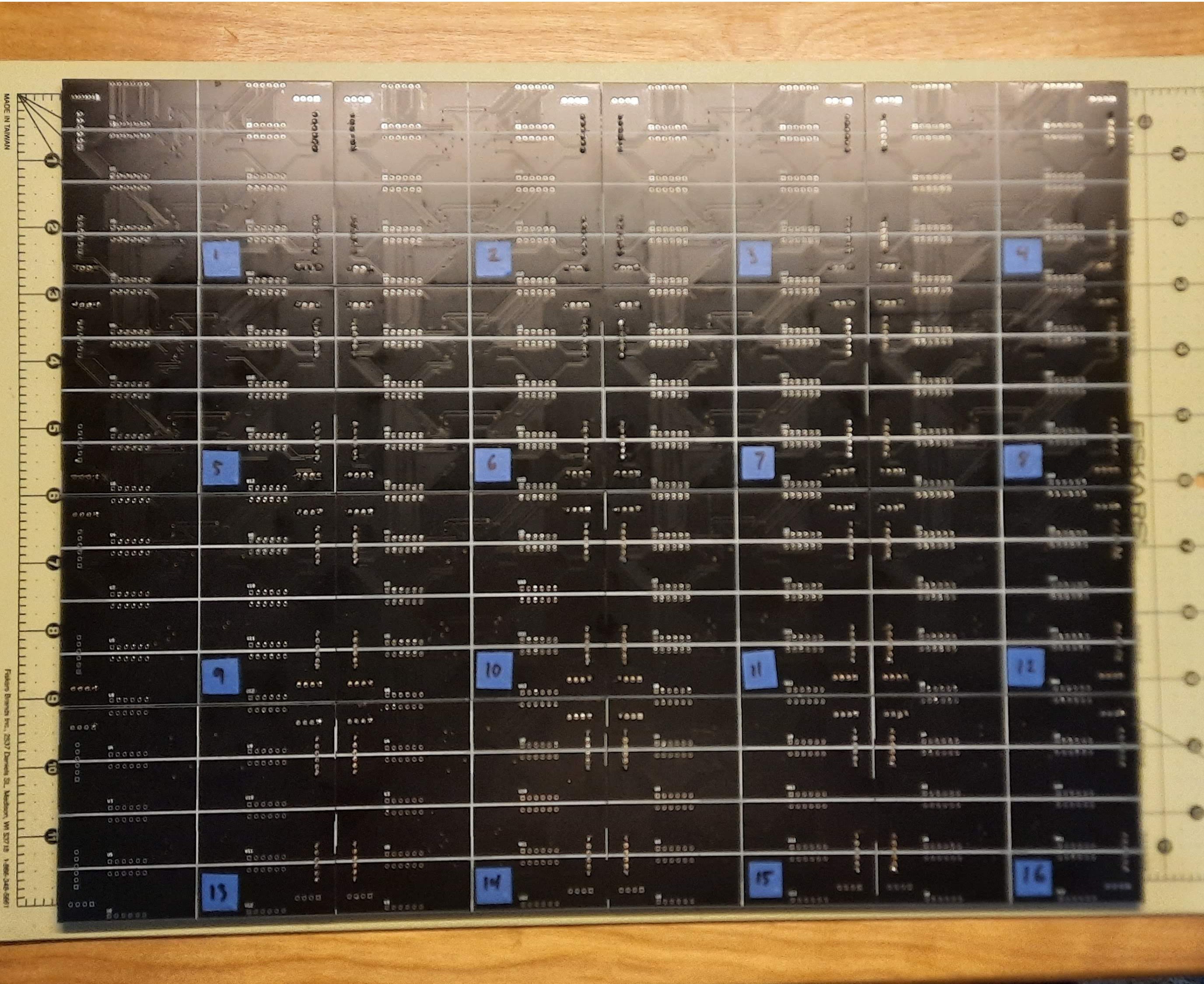
I started with the display boards as I new they were going to be a little finicky to get everything lined up. Managed to get the connectors all 16 boards lined up. I may or may not have had to reverse things a few times.
![]()
All 16 boards connected.
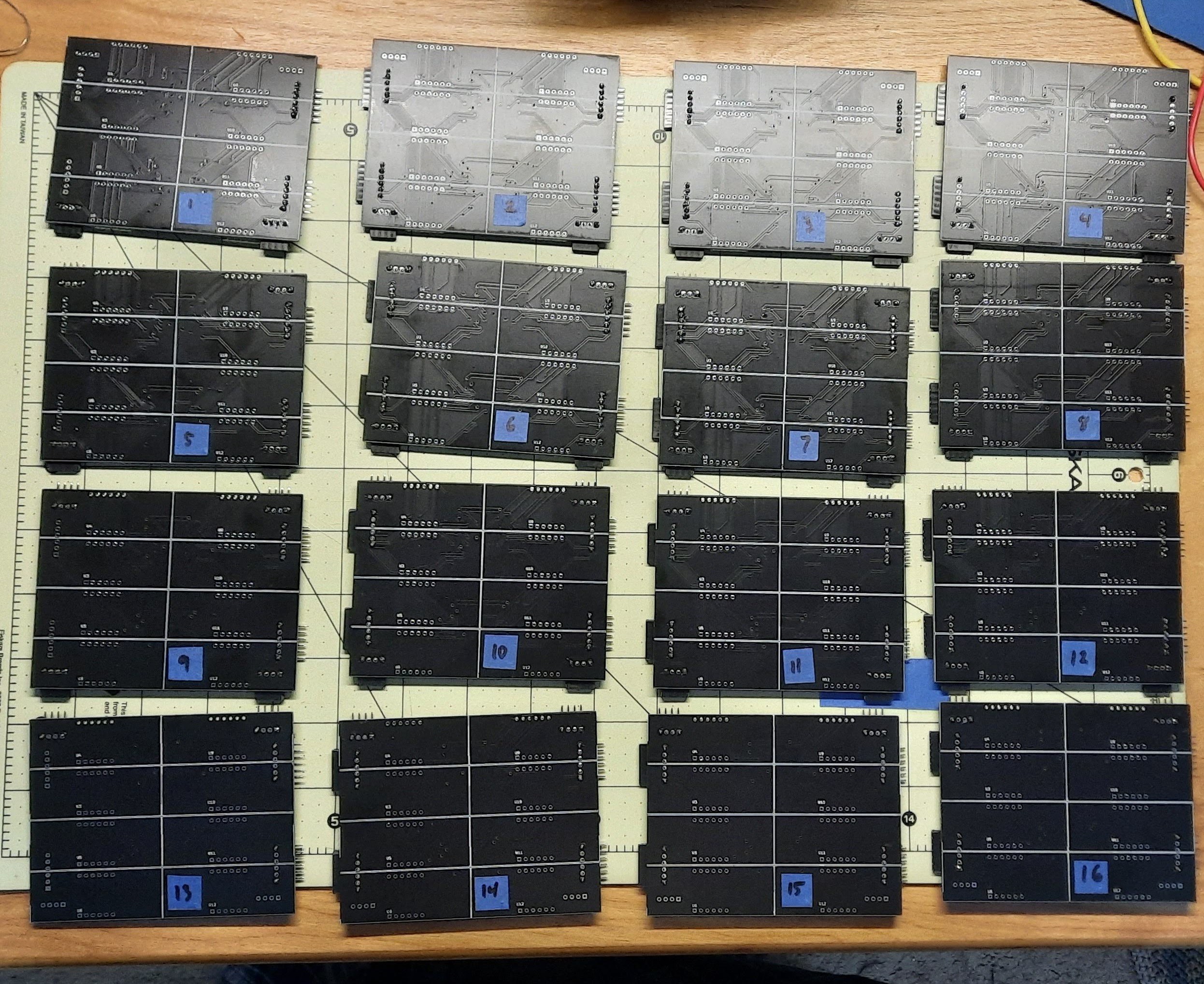
![]()
Boards disconnected.
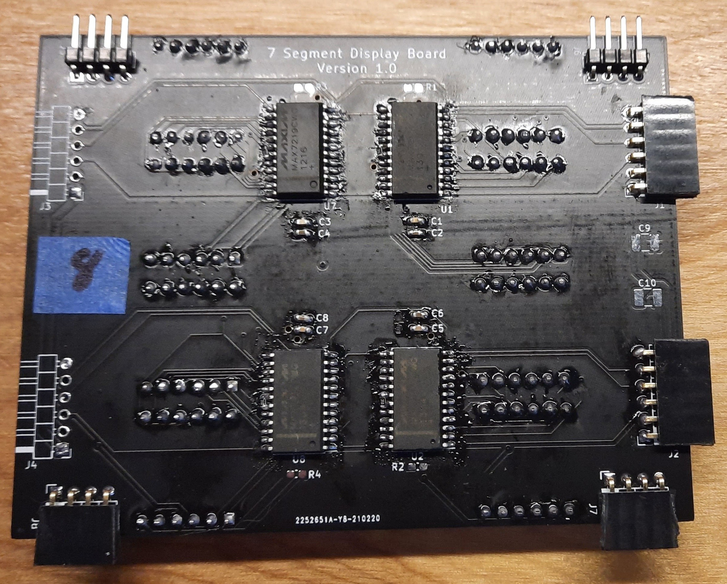
---------- more ----------Now to install the discrete components, MAX7219s and displays. After installing parts but before cleaning.
![]()
Now time to test!!!!
-
The order and the wait
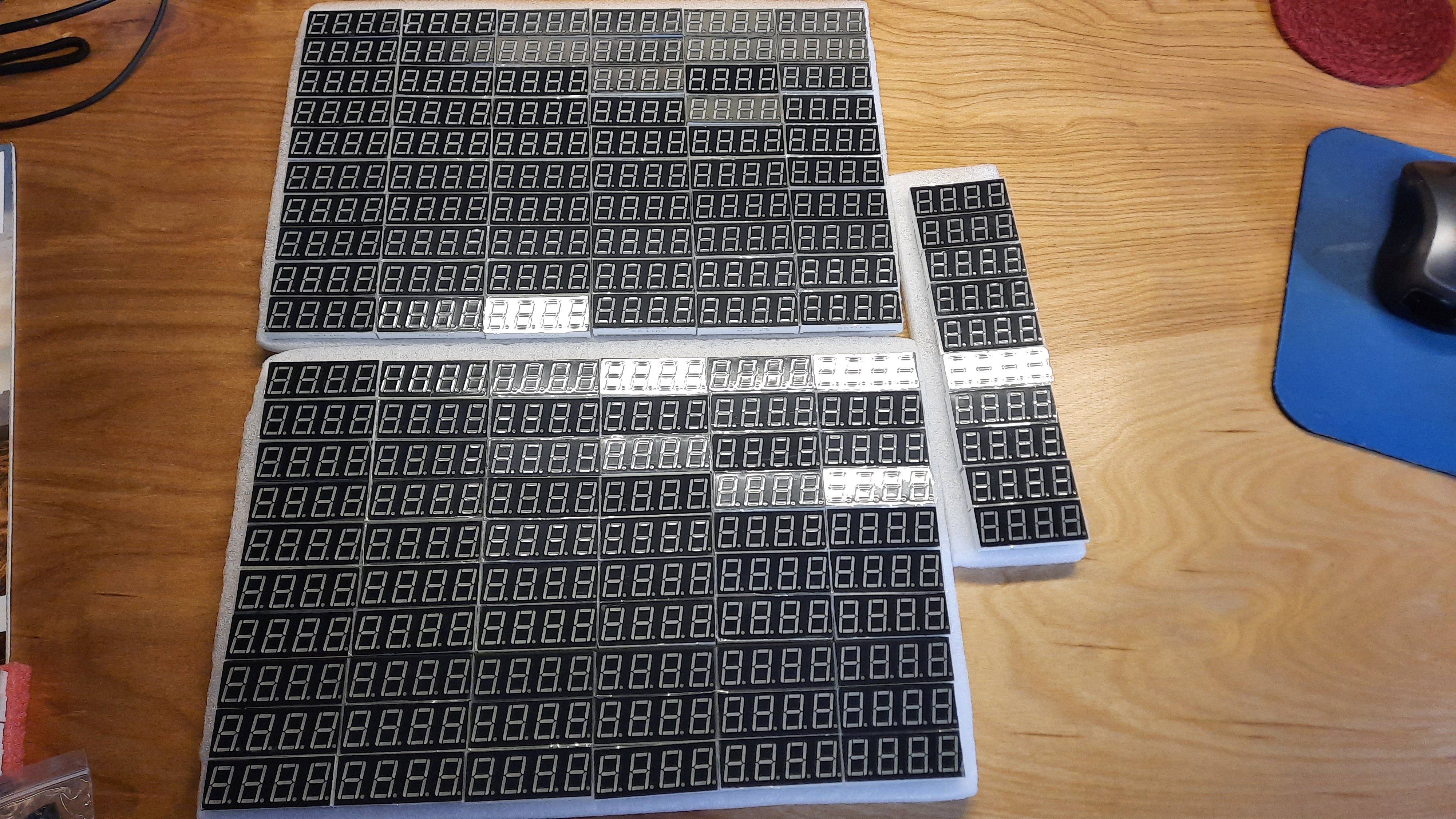
05/24/2021 at 23:01 • 0 commentsI ordered the 7 segment displays and a handful of MAX7219s from AliExpress and began the long wait for them to arrive. Needed a total of 64 MAX7219s and 128 seven segment displays.
After what felt like 50 years the parts finally arrived. After laying out the displays I finally got an idea of how big this display would be. All I have to say is it is going to be gloriously bright. Once I verified all of the display dimensions and footprints on the two layouts they were ordered from JLPCB.
![]()
-
Board Design - Display Board
05/24/2021 at 22:56 • 0 commentsTo control the metric buttload of individual segments I decided to use the Pi PICO as it seamed to have the grunt needed to get the job done. There is an FPGA between the PICO and the display matrix. The FPGA performs the mapping between a 2 dimensional array and the 7 segment digits. More to come on the FPGA internals.
Major components in the design:
- MAX10 FPGA
- Pi PICO
- MCP7940 Real Time Clock
- TMP75 Temp sensor (just because I had some in my box of parts)
- RFM69HCW RF module
- Footprint for two HUB75 display chains or 8 SPI data out chains buffered to 5V.
Pretty proud of how the layout turned out. Love working with FPGAs as the the pinout is almost infinitely adjustable.
![]()
-
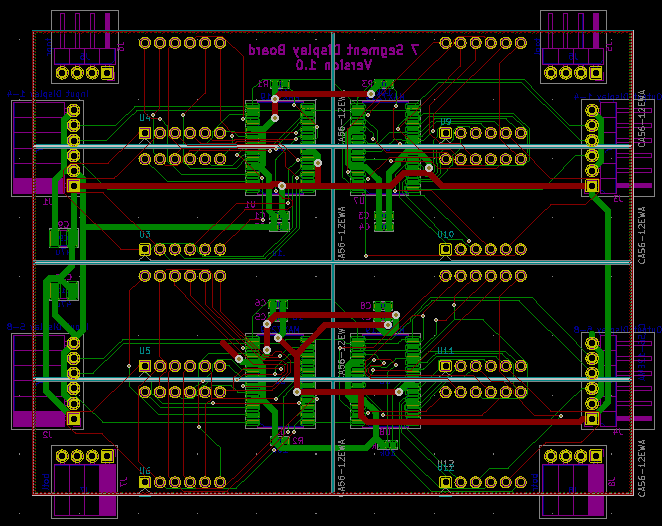
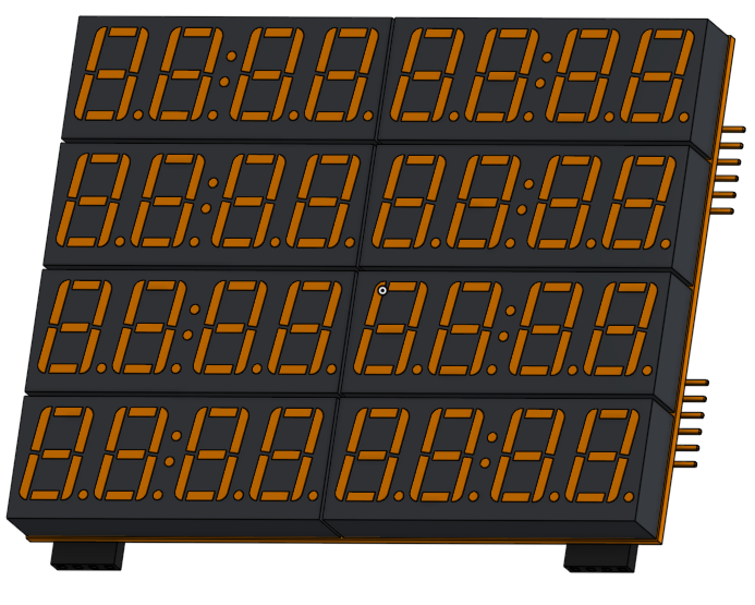
Board Design - Display Board
05/21/2021 at 22:09 • 0 commentsI started off with the display board design. The schematic and PWB layouts were done using KiCad as it is free an fairly powerful. The board design is fairly straight forward. Right angle .1" headers are used between the boards in the X and Y directions. The design contains four MAX7219's each driving eight 7-segment digits. A smattering of capacitors were tossed in for good measure as the matrix drivers can be real current hogs. The LED displays are 0.53" high.
![]() ---------- more ----------
---------- more ----------Once I got the layout done and thanks to the wonderful KiCad team I can view the design in 3D. Which is actually pretty nifty. The actual displays to be used do not have the colon in the middle but that was the only model I could find for the display size being used.
![]()
-
Concept Phase
05/21/2021 at 21:44 • 0 commentsAfter seeing things like the DigitGrid and the Pligboot Matrix I decided that I was going to build a 7 segment LED matrix to add to my collection of LED clocks and displays.
First off was deciding how big I wanted to go. I decided on a nice round 512 seven segment displays. I did not want to have one massive board to contain everything so I broke the display board into sixteen smaller boards.
Each board will contain a four MAX7219's driving two four character 7 segment displays for a total of 32 characters per board.
I decided that driving all sixty four MAX7219's in one massive SPI chain was probably a bad idea so they have been configured in eight rows of eight controllers each. I figured this gave a good balance between speed and not driving myself crazy with wiring.
To control all of the display board I decided to go with an Intel MAX10 FPGA as I have worked with them a lot. A Pi Pico does all of the graphics computation and feeds the data to the FPGA for mapping to the 7 segment array. Kind of an elegant solution as the software does not have to care what it is displaying but rather just needs to know the resolution.
Number Matrix
A matrix built from sixteen boards each containing eight - four character seven segment displays for a total of 4096 individual segments.