zaphod
-
2020, V2, and the current state of the hardware
05/27/2021 at 17:22 • 0 commentsIn my last post I discussed some of the problems I had with the version 1 hardware at the end of 2019. There were enough issues with the hardware that I decided that it would be worth redoing the board and so I started a version 2 design, but didn't get very far before school started again and I had to put the project on hold.
In 2020 I started working on my undergraduate capstone project, and the combination of capstone work and regular school work/internship work meant that I didn't end up having enough time to work on this project for all of 2020.
After finishing school in April of 2021 I had some more free time again and dug out this project and reevaluated what I'd completed so far.
Rather than moving forward with the V2 hardware design, which wasn't well developed and had been rushed at the end of 2019 I decided to start fresh with a V3 hardware design that would address many of the issues I faced with the V1 hardware.
I ended up making the following changes and simplifications to the V1/2 designs:
- move voltage regulation off the board (3v3 power supplies are easy to come by and there's not much value in adding a regulator to the board)
- fix as much of the wiring as I could (e.g. the 3v3 line on the ICSP header)
- move the master oscillator off board. Since I wanted this to be flexible anyway there is no point in adding it to the main PCB
- better protection on the USB curcuit (added TVS diodes and grounded the USB shield)
- Rather than trying to get the micro to FPGA wiring correct I decided to just break everything out to a pin header and connect GPIOs manually
- this basically make the board a reusable devboard with an FPGA and micro on it, but it was supposed to save me from needing another revision of the hardware if I managed to mess up connections again
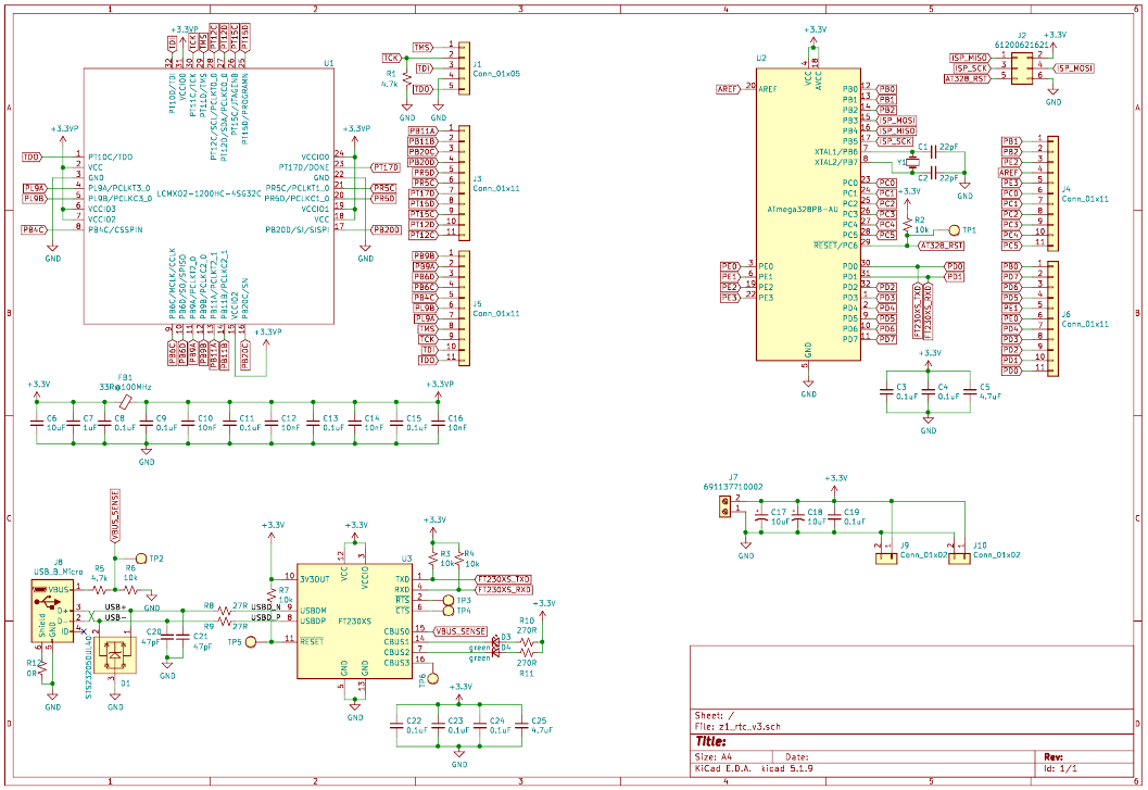
With these simplifications in mind I went ahead and redesigned the board with the same parts as the version 1 design from 2 years ago. The final schematic is as follows:
![]()
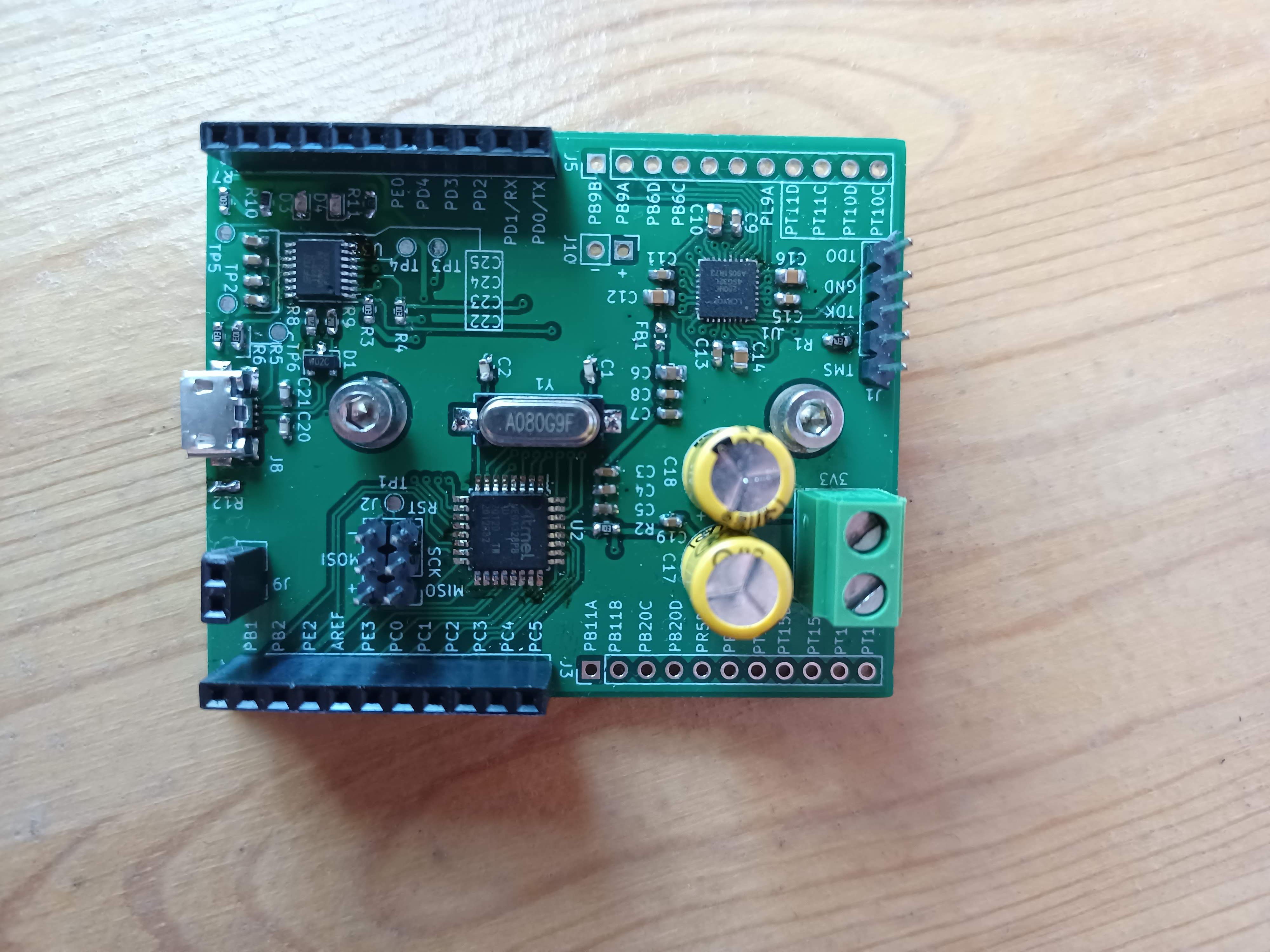
I ordered and assembled the boards which looked like this:
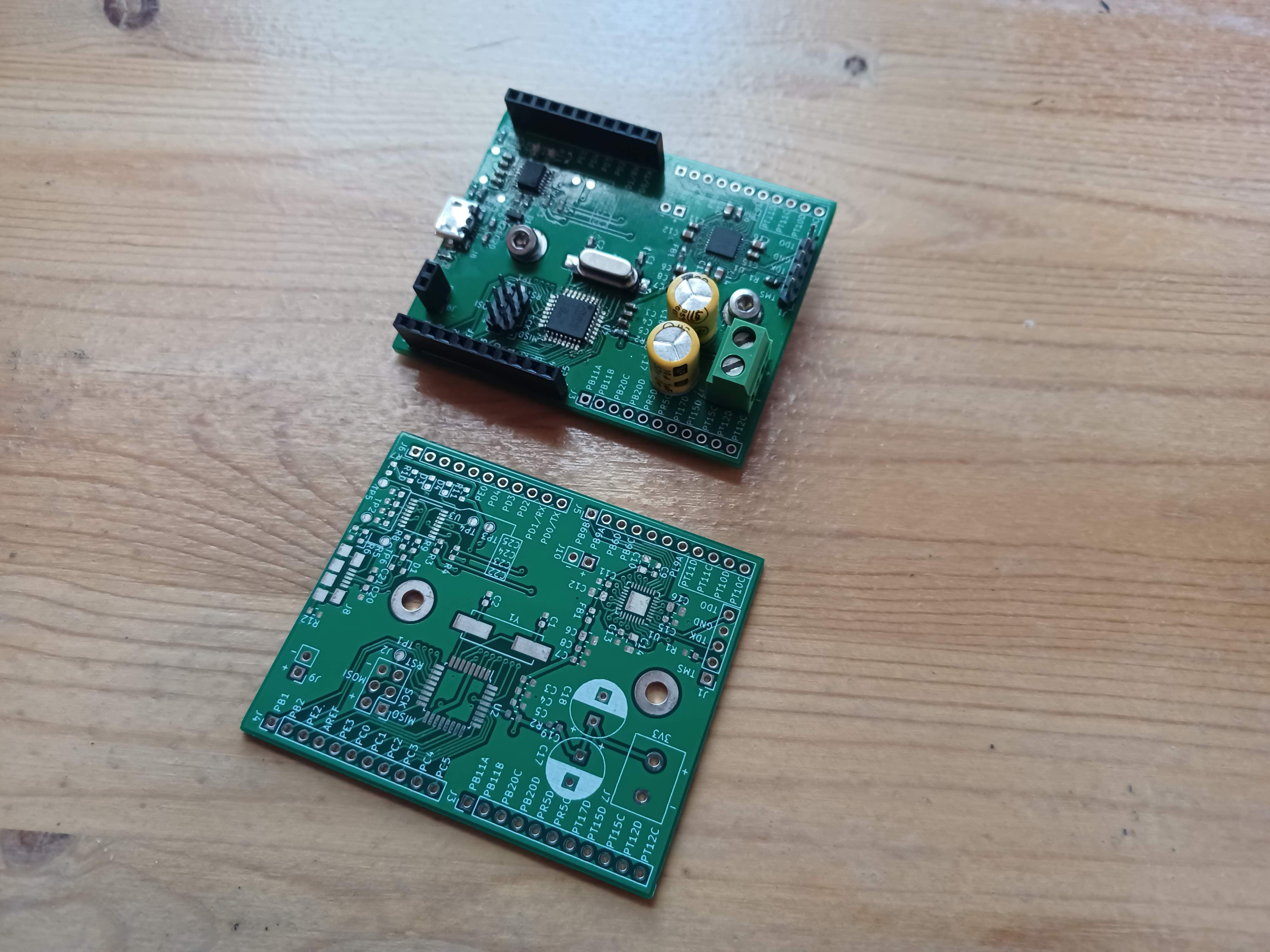
![]()
fully assembled board, From left to right the ICs are: FT230XS, ATmega328PB, LMCXO2-1200HC-4SG32C ![]()
a blank board beside a populated one This board was largely a success!
- The ATmega and associated programming circuit all seems to work ok
- Protection on the FTDI part seems to be working (all though you can never really be 100% sure about these things)
- I was able to configure the FPGA
However, there was one big issue... The FPGA kept dying on me. I was able to get two soldered down, and powered up, but after a few minutes they would short out and burn. Before it burned up I was even able to configure one of the FPGAs successfully, which contributes to the mystery.
Further confounding debugging this issue is the current parts shortage. I blew up all of the spare FPGAs I had left over from when I bought parts in 2019, and now they're out of stock everywhere. :(
I tried to check some of the obvious stuff to see if I could figure out a reason that the FPGAs were burning, but I wasn't able to come up with anything
- as far as I can tell the schematic is correct and the board layout is fine
- I checked my power supply's startup for any nasty transient spikes, but was unable to find anything (which doesn't mean they aren't there, but the other chips seem happy, and the FPGA is behind a ferrite bead and a fair amount of smoothing caps)
Unfortunately I wasn't able to check anything else electrical. However, I also had some paranoid Ideas about what could be wrong:
- of the FPGA I had on hand both were originally ordered in 2019 and one had been stored in an opened bag (the micro and ftdi chip were stored in sealed bags), and the other had been soldered to a V1 board, so it possible (but untestable) that poor handling had caused both of the chips to fail somehow
- The other idea that I had was that there was something wrong with the flux I used to solder the FPGA.
I'm specifically suspicious of the flux since its not actually proper electronics flux, its just hardware store plumbing flux. I have used it before on electronics without issue, but the only other time I've used in on stuff this fine pitch was for the V1 board.
you'll recall from the last post That the V1 board suffered from weird intermittent issues with all of the ICs failing randomly (all though I think that the FTDI chip was failing due to poor shielding/transient protection). The same plumbing flux was used on all of those chips, so that's another reason to be concerned.
Since I'd soldered, tested, and burnt out the FPGAs before the rest of the board I decided to just assemble the rest of the board without using the plumbing flux (after carefully cleaning up all of it that I could see on the unpopulated portion of the board). Thus far the non-fluxed circuits seems to be behaving properly.
The evidence against the flux is basically circumstantial, but I'm suspicious anyway.
So This leaves me with a board that works, but absolutely no FPGAs. :(
There are two possible solutions:
- embed the TinyFPGA dev board that I have
- Change to a different FPGA/CPLD that I can still buy
I don't like 1, because I want a project with an embedded FPGA dammit. Therefore I'm pursuing option 2. Either way I'll probably be doing a V4 of the board.
That covers all of the historical background on the electronics for this project, and subsequent posts will describe what's currently happening.
The next post however, will discuss the mechanical design of the device, and show off my fancy new 3d printed case.
-
version 1 hardware, circa 2019
05/26/2021 at 22:25 • 0 commentsThe first version of this project's hardware was developed in the fall of 2019. Due to how my school/co-op cycle worked I only had time to work on this project between September and December 2019. Since four months wasn't really enough time to get things done properly I rushed a lot of stuff, specifically the v1 PCB design, and as a result it didn't really work properly. Therefore this post will explain (one method of) how not to build a digital real time clock.
To begin prototyping I basically just connected some devboards on a breadboard. Recalling the block diagram in my last post The initial prototype implemented the various blocks as follows:
Master Oscillator:
for testing purposes this was just the output of my function generator. This is not nearly accurate enough to meet my time keeping specification, but it did let me work on developing the RTL for the counting logic.
Counting Logic:
This was implemented with a TinyFPGA Ax2 devboard. This is a very barebones (and easy to use) dev board for the Lattice LMXO2-1200HC-4SG32C, which is a basic fpga/cpld in Lattice's machXO2 family of devices. This part was selected entirely based on the fact that the TinyFPGA dev board was readily available to me, and reasonably well documented. Probably there are better ways to select parts for a project, but oh well.
Time Computation:
The time computation was handled with an ESP32-WROOM32D devkit-c development board. This was selected since I had it in my parts box all ready and I all ready knew how to put micropython on the ESP32.
Display and Set/Reset logic:
I basically ignored this for the earliest prototype, and just had all of my i/o via the devkit-c's USB serial port.
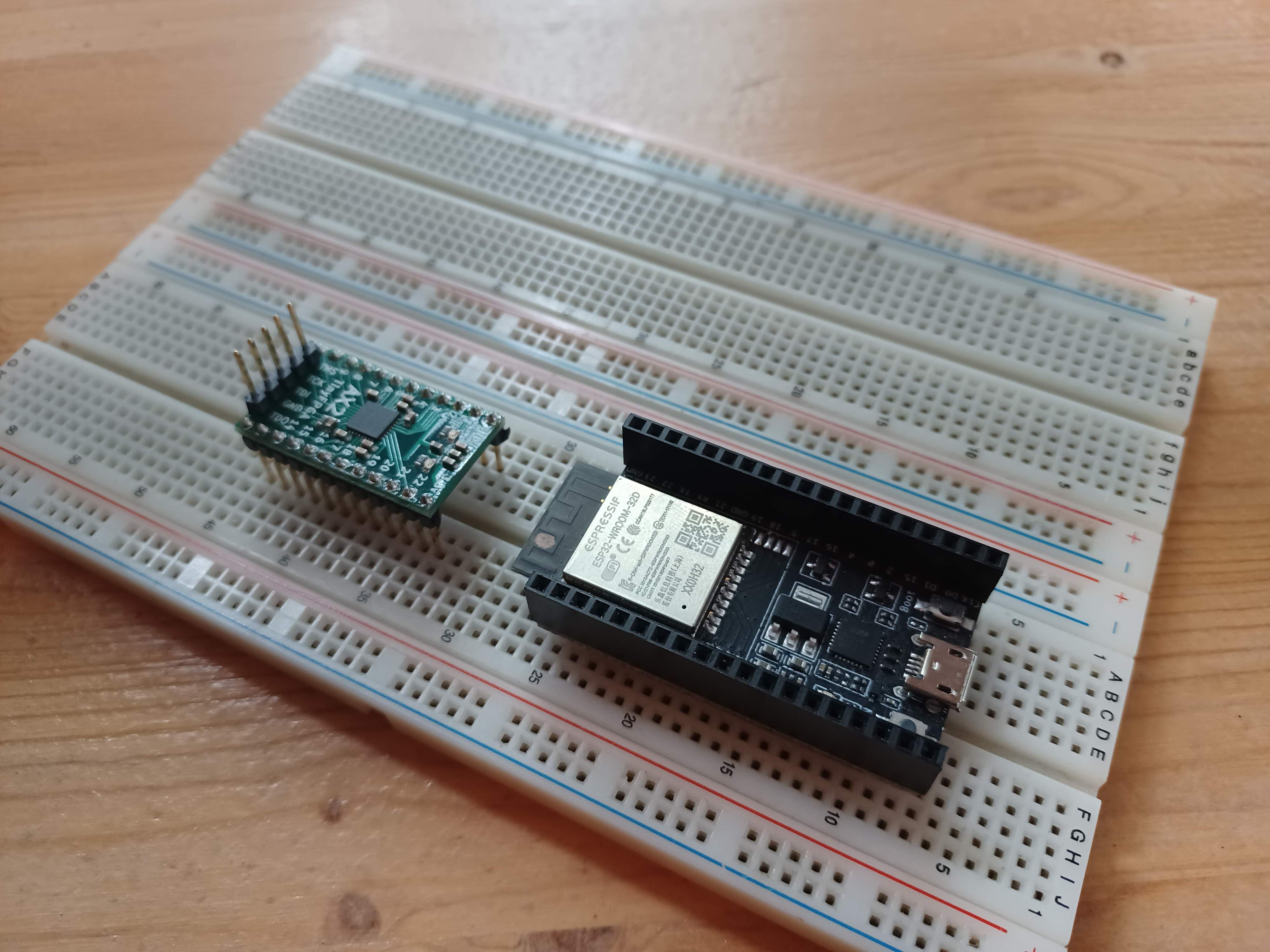
A recreation of the initial prototype:
![]()
there were also some wires and a function gen The initial prototype was mostly used to develop the RTL for the FPGA. I spare the gory details of the exact counting logic implementation (the code is on github here if you really care), and just summarize how the counting logic works.
Basically, the RTL runs off of the FPGA's internal resonator which is faster than the master oscillator frequency (FPGA clk ~80MHz, master oscillator ~10 to 20MHz), and every tick it checks to see if the output of the master oscillator has risen. If it has then the FPGA increments a register. when the value in this register is equal to the master oscillator's nominal frequency we know that one second has elapsed, and a signal is generated to increment the Seconds Register. The Seconds Register holds an epoch (some absolute number of seconds since a known time), and is the basis of the time count. I use a 64 bit register to hold the unix epoch because the universe began on 01 Jan 1971.
The other part of the RTL is a state machine that implements a simple SPI protocol that allows a bus-master to query the FPGA for the current value of the epoch, and to allow the bus-master to load a new epoch into the seconds register.
There was also some non-sense with external triggers that I abandoned part way through. (the idea was basically to allow the FPGA to measure the time that elapsed between two trigger signals)
The above is all well and good, but it glosses over two important details:
- comparing a non-power of 2 number to the value in a register sometimes misses, especially if the register is incrementing quickly since the value of the register might not be stable for long enough for the comparison to happen reliably
- polling the state of the master oscillator introduces some error in the time count, since a rising edge on the MO, might not be detected until nearly one FPGA-clk has elapsed
Issue 1. turned out to be important since I want to be able to synthesize a 1Hz signal from non power of 2 master oscillator signals. The solution is pretty straightforward though. Basically I just pipelined the divider so that the first stage is a reliable rollover counter with a width equal to the largest power of two less than the MO's nominal frequency, and the second stage, which is now much slower, is a less reliable comparison counter which derives the required 1Hz signal. There's probably a better way to do this, but this seems to work for now.
Note: the rollover counter doesn't guarantee that an MO edge is never missed, it just doesn't runaway if a comparison is missed, so I think it might still be a potential source of error. I'd need 30mins and a whiteboard to explain what I mean here properly, so @ me if you really care for some reason lmao.
Issue 2. This is a known source of error with an upper bound, and I'm not smart enough to think of a better way to deal with it. I guess the counting logic was bound to introduce some amount of error somehow (I bet there's a famous result that I don't know about in information theory that proves this)
ok. that was more RTL talk than I wanted to write, but whatever
once I the counting logic working on my bench it was time to start making a board, which required selecting components. The big items were the Master Oscillator (MO), FPGA, and the microcontroller.
The FPGA was easy, since all of my designs thus far had targeted the Lattice part in the tinyFPGA Ax2 I just picked it. (hard to solder QFN-32, but c'est la vie)
For the master oscillator I scraped through Digikey for a part that met my accuracy specifications, and operated on 3v3 (required to ensure that I didn't need a level shifter between the MO and the counting logic, which is just another source of potential error). I ended up with the OX4150A-D3-1-20.000-3.3-7 which is an oven compensated crystal oscillator with a frequency stability of ~10ppb.
(This is well in excess (3 orders of magnitude!) of the ~12ppm required to be more accurate than my Casio wristwatch, but the accuracy of a real time clock and frequency stability of an oscillator are different (but related) things. (even deeper aside, it seems like my other wristwatch, a Timex, might be more accurate than the Casio, but Timex doesn't publish good datasheets for their watch movements...))
For the microcontroller I abandoned the ESP32 for an atmega328pb since writing embedded code in python is cheating. (and also I didn't want wi-fi and bluetooth).
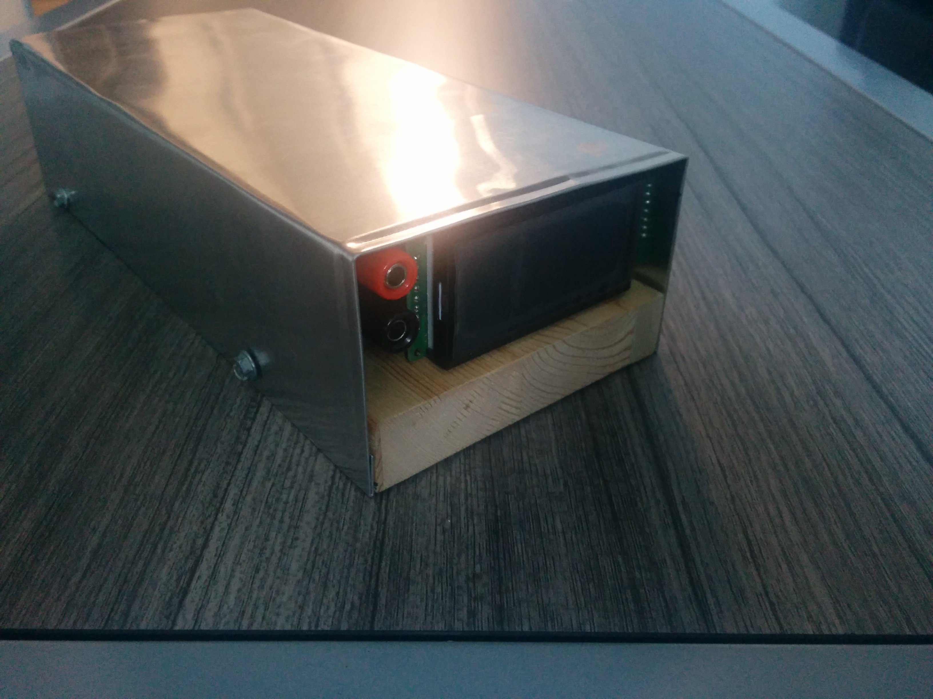
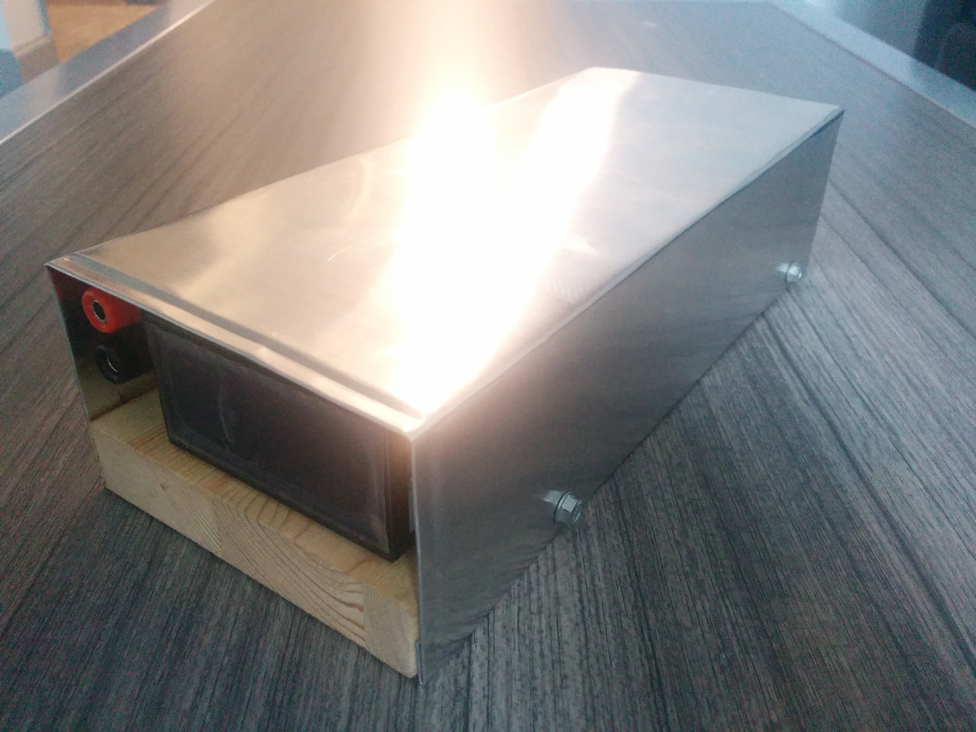
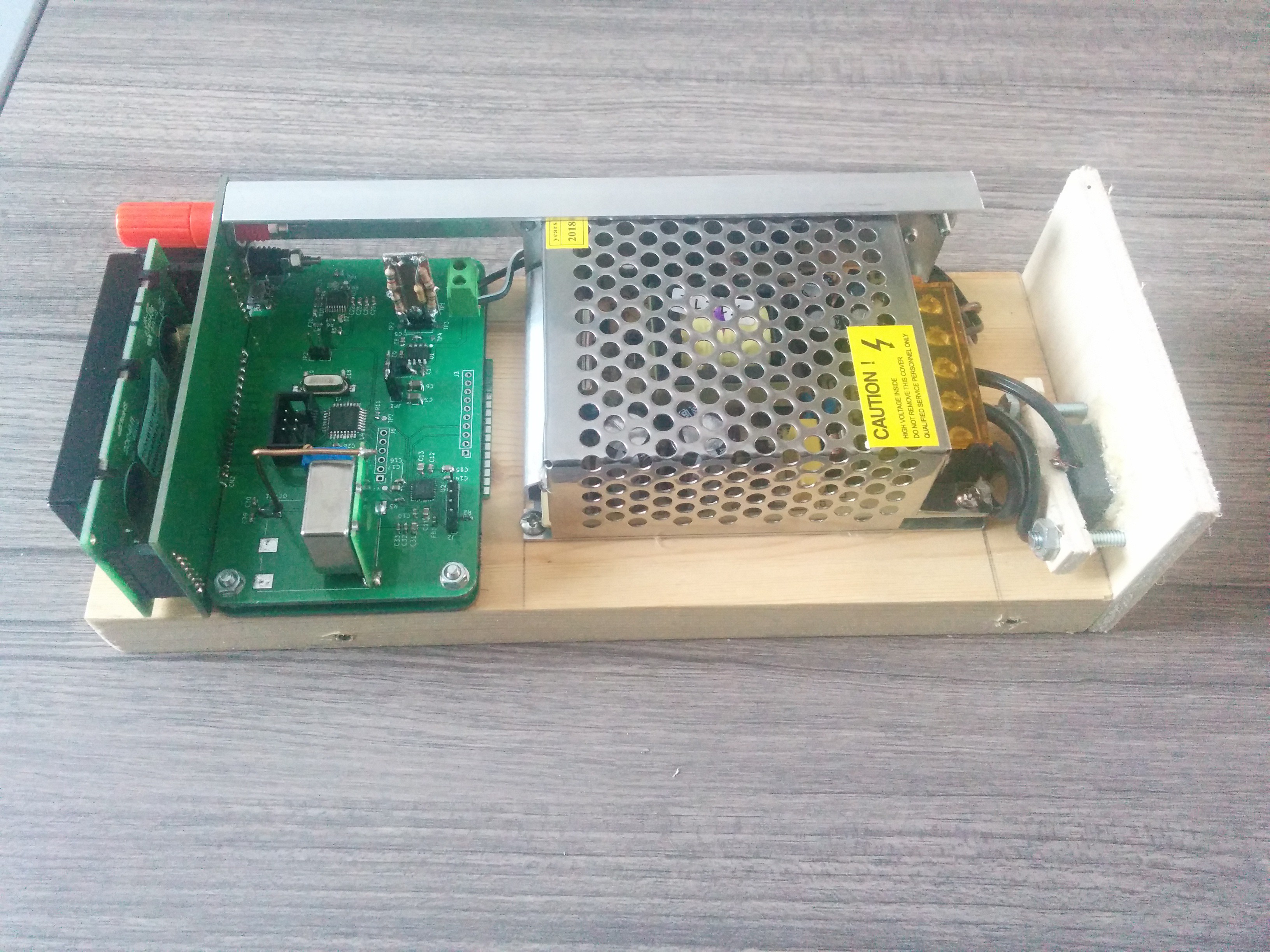
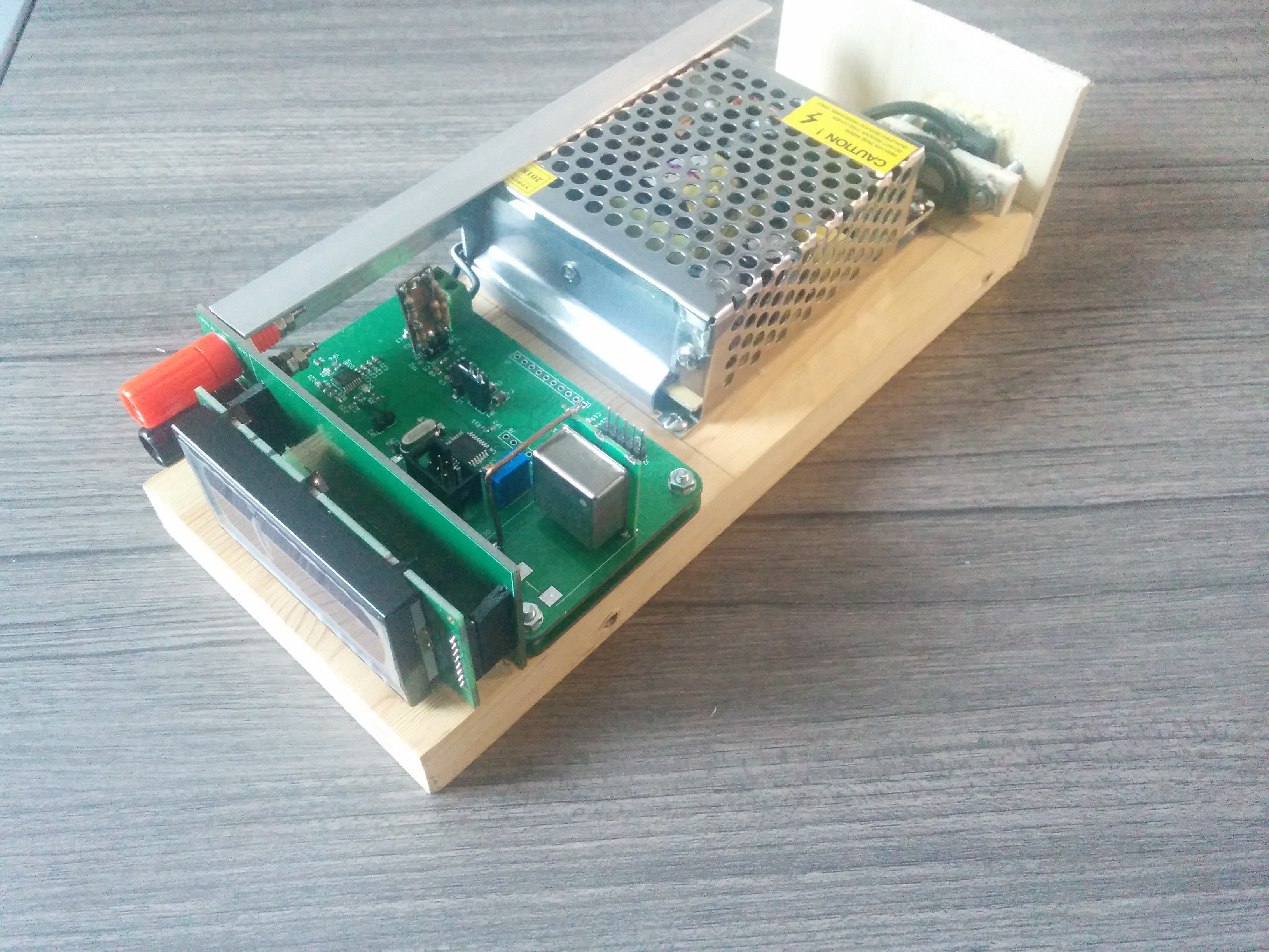
For the display I just picked a generic four row character LCD from digikey.These parts and the associated support circuitry (voltage reg, and FTDI USB/UART bridge) were haphazardly slapped on a board, assembled, and programed (ish) during my Christmas break. The result was the following:
![]()
ignore the Banana plugs, they are part of the abandoned elapsed time measurement feature ![]()
![]()
![]()
Which looks neat, but had some serious problems.
- power: the power supply is a 12V junk box special, and the clock runs on 3v3, so a buck converter was required. This fine, but during bringup I manged to short out the board's power rails and explode some buck converters :(
- this shorting happened because I didn't have a 3v3 connection on the atmega's ICSP header, and needed a flywire to make my programmer work
- the footprint for the OCXO was mirrored (confusing datasheet drawing)
- insufficient protection on the USB input. The sheild was left floating, and I didn't TVS diodes on the signal wires (dumb, huh?) and this resulted in some dead FTDI chips
- mixed up micro to FPGA/Display connections (partially fixed in software, partially fixed with bodge wires on the bottom of the board)
- weird intermittent failures/low assembly yield of the FPGA and micro circuits (seemed like maybe an ESD issue, but now I think it might have to do with the flux I was using. more on this later)
- not a great case (I didn't have a 3d printer yet)
despite its myriad flaws, The V1 hardware worked enough that I was able to get my software tools figured out and upload some testcode, before I fried my last voltage regulator.
After that I just went and bought a 3v3 power supply for this project and bypassed the burned out buck converter, but then I started running into the aforementioned intermittency issues with the micro. I was also completely out of time, since a new school term was starting.In the next post I'll explain why this project was mothballed for all of 2020, what happened to the V2 hardware design, and the state of the current V3 hardware.
-
Ancient History
05/25/2021 at 23:54 • 0 commentsThis project actually began in the fall of 2019. I needed to learn verilog for an internship (they only taught me VHDL in school), and so I was messing around with a couple different FPGA dev boards (Terasic DE10-Lite, and the TinyFPGA AX2). Eventually I figured it would be fun to try and make a PCB with an FPGA on it, since I'd never done that before.
Since I didn't want to just make a dev board I needed a project, and I thought it would be cool to try and make a freestanding digital real time clock.
- freestanding: contains its own oscillator and does not rely on an external time source or synchronization signal like the utility frequency or GPS
- digital: since I am not clickspring :(
- Real Time Clock: should have a friendly display that I can show to normal people and say "this is a clock that I made"
I also had some other requirements:
- should be more accurate than the quoted accuracy of my Casio wristwatch (better than +/- 30 s/mo, or ~12ppm for a standard issue 30 day month)
- should show off lots of hire-able skills (ended up signing up for grad school instead... whoops)
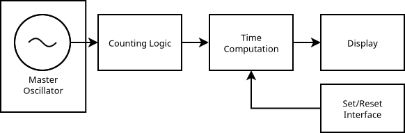
In order to meet these objectives I came up with the following architecture:
![]()
Master Oscillator:
This is the ticking heart of the clock. It would be cool to build my own very accurate oscillator, but that's a project unto itself. It would also be cool to use a surplus rubidium frequency standard as the master oscillator, but that would also be a bit of an undertaking. Therefore to keep things simple (for now) I decided to use a prebuilt oscillator module (more discussion about the specific part later). However, I'd like to keep the counting logic oscillator agnostic, in order to ensure that its easy to swap out the oscillator at a later date.
Counting Logic:
every tick of the oscillator needs to be counted, and every 1/f ticks the counting logic should increment a seconds register. This is the FPGA part of this project.
Time Computation:
Could I compute time and date from a seconds register, drive a display, read some buttons, and deal with a UART/USB connection from an FPGA? yeah probably. Do I want to? not particularly. Therefore all of these tasks will be carried out by a microcontroller.
Display:
should be something nice and friendly to read, preferably with some flexibility since I want to display strings like:
"PST: 19:32.57, 12 NOV 2022"
in a way that doesn't require learning how to decode an array of blinking LEDs.
Set/Reset Interface:Finally I need a way to set the time that the clock displays. Since the Time computation is going to be handled in a microcontroller, the set reset interface needs to talk to the microcontroller. I decided that the easiest way to set the time would be over a USB serial port since then I could write a little utility that would synchronize the clock to current time of the computer that its plugged into.
In the next post I'll talk about the parts I picked, and the version 1 hardware design.