 Alex M Sunny
-
1ROS
ROS (Robot Operation System) is a framework that facilitates the use of a wide variety of "packages" to control a robot. It acts as a middleware. Although ROS is not an operating system. ROS provides low-level device control, implementation of commonly-used functionality, message-passing between processes, and package management also provide packages range all the way from motion control, to path planning, mapping, localization, SLAM, perception, and more. ROS provides a relatively simple interface, and the ability to of course create custom packages.
We are using Raspberry Pi 3 for this project. Raspberry PI 4 and Jetson nano would be a great alternative for this project.
Get the disc image
We downloaded the Ubuntu 16.04 Xenial with pre-installed ROS from Ubiquity Robotics. The link provided has all the steps to how to install it.
- Download the image from the top of the page.
- Flash it to an SD card (at least 8GB) Class 10 preferable.
- Connect to the WiFi network that starts with
ubiquityrobot. Password isrobotseverywhere. - Go to Terminal, and connect to your Pi using
ssh ubuntu@10.42.0.1. Password isubuntu. - Run
roscoreto make sure that things are working properly. If you get a warning/errors, try stopping ROS and starting it again withkillall -9 roscore.
-
2Working with ROS
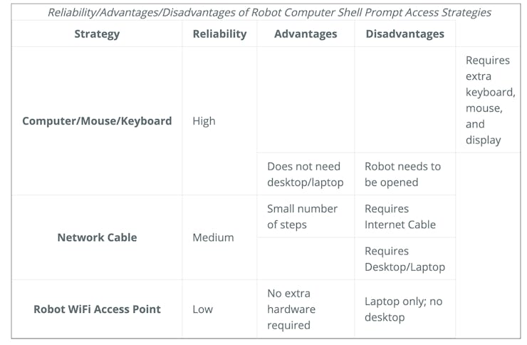
There are three ways you can control and code your robot.
![]()
The easiest way was to connect the monitor and keyboard to raspberry pi to work with code.
Something we would want to be able to do is to access the ROS communication messages from our laptop.
Spin a Linux machine with ROS Kinetic Kame. Either a virtual machine or a real machine. I used a VMWare-Fusion with Ubuntu 16.04 We will refer to that machine as the Observer machine. The robot is the Master.
You can follow this tutorial to set up the robot as amaster and Laptop as an observer machine.
Notes
- RVIZ won't work in VNC. I tried and failed. You need to use Virtual Box or Vmware to work with ROS remotely.
-
3Connecting to WiFi
Follow this website to know how to connect your robot to your wifi.
- On the robot machine,
pifi add YOURNETWOKNAME YOURNETWORKPASSWORD - Restart the Pi,
sudo reboot. Now the Raspberry Pi will connect to your WiFi network on startup. To connect to it, connect your computer to the same network, andssh ubuntu@ubiquityrobot.localwith the passwordubuntu.
Woo! Now both machines have internet and can communicate over SSH.
- On the robot machine,
-
4Testing the lidar
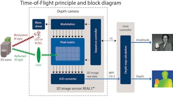
How does LiDAR work?
The basic principles for traditional LiDAR have been seen in time-of-flight-based distance measurement and triangulation-based measurement.
The ToF concept uses the delay time between the signal emission and its reflection to compute the distance to the target. The time delay is not measured for one particular beam’s round trip.
![]()
Basic overview of how ToF works. Image courtesy of Mark Hughes.
Instead, the phase shifts for multiple signals are used to indirectly obtain the ToF and then compute the distance. The triangulation method is used to measure the distance between the source and the obstruction.
Using 3D LiDAR offers richer information about the environment and more accurate and finessed maps in realtime.
We are using the YDLIDAR X4 for this build. The first step is to install the necessary drivers. The driver is a ROS package.
cd catkin_ws/src git clone https://github.com/EAIBOT/ydlidar.gitcd ../ catkin_makeroscd ydlidar/startup // Make the shell script to an executable sudo chmod 777 ./* sudo sh initenv.sh
- Go back to your catkin workspace, and run
source devel/setup.bash
- Run
catkin_make
Test the lidar with
roslaunch ydlidar lidar_view.launch
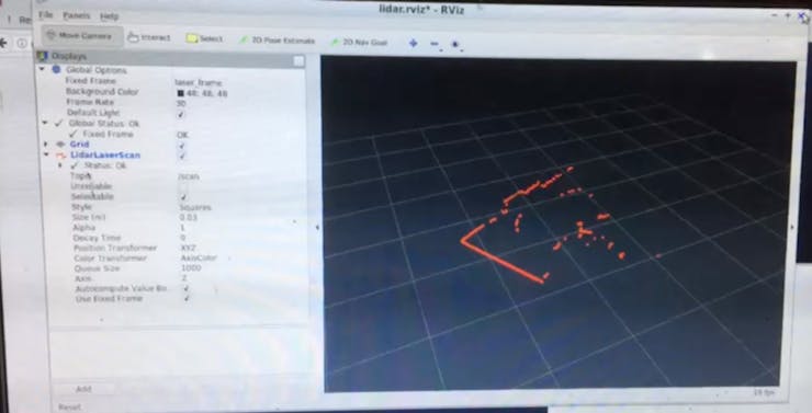
Visualize the scans in Rviz, by adding the topic /scan.
point cloud using Ydlidar X4https://youtu.be/Z1Y9U8EZ1DE It may look something like this.
![point cloud of my room.]()
point cloud of my room.
-
5ROS + Arduino communicationWe know that the Raspberry Pi is the most important part of our robot. The Arduino will be controlling the motors.So we require communication between Raspberry Pi and Arduino, we will install rosserial, a ROS module that enables Arduino communication, on both the Raspberry Pi and the Arduino.
- Following the steps from the ROS website, we start with installing the package.
sudo apt-get install ros-kinetic-rosserial-arduino
- and then,
sudo apt-get install ros-kinetic-rosserial
- If you are using a ROS version different from Kinetic, change the word
kineticto your version.
In the following commands, substitute
catkin_wswith the name of your catkin workspace.git clone https://github.com/ros-drivers/rosserial.gitcd catkin_wscatkin_makecatkin_make install
In your Arduino IDE, install the rosserial library. Search for
rosserialin the Library Manager and install it.Follow this link to run HelloWorld example,
- On the Raspberry Pi
roscore
In a second Raspberry Pi terminal,
rosrun rosserial_python serial_node.py /dev/ttyACM0. ChangettyACM0with the port of your Arduino. You can check the port by navigating to~/dev/, and observing which files disappear and re-appear when the Arduino is disconnected and connected.In another Raspberry Pi terminal, In a third terminal run
rostopic echo chatter
You will the messages.
-
6Installing Hector-SLAM
We can install Hector -SLAM for mapping. We found this video by Tiziano Fiorenzani and the official resources on the ROS website helpful for setting Hector-SLAM up.
Clone the GitHub repository to your catkin workspace. Navigate to the
srcfolder and rungit clone https://github.com/tu-darmstadt-ros-pkg/hector_slam.git.
- Clone the GitHub repository to your catkin workspace. Navigate to the
srcfolder and run
catkin_makesource ~/catkin_ws/devel/setup.bash
We need to make a couple of modifications to the Hector SLAM tutorial files in order for them to work with our setup. We first take note of the transformations available to us on the
\tftopic, and the reference frames they use.- Spin the lidar node, with
roslaunch ydlidar_ros lidar.launch
- Check the communication on the
/tftopic with
rostopic echo /tf
- We will get only one transformation:
--- transforms: - header: seq: 0 stamp: secs: 1578619851 nsecs: 284012533 frame_id: "/base_footprint" child_frame_id: "/laser_frame" transform: translation: x: 0.2245 y: 0.0 z: 0.2 rotation: x: 0.0 y: 0.0 z: 0.0 w: 1.0 ---
So we see that we have only two frames. Namely
/base_footprintandlaser_frame. We will update the file~/catkin_ws/src/hector_slam/hector_mapping/launch/mapping_default.launch
Find this line and change from
<arg name="odom_frame" default="nav"/>
to
<arg name="odom_frame" default="base_footprint"/>.
At almost the very bottom of the file, change from/to:
<node pkg="tf" type="static_transform_publisher" name="map_nav_broadcaster" args="0 0 0 0 0 0 map nav 100"/>
to
<node pkg="tf" type="static_transform_publisher" name="map_nav_broadcaster" args="0 0 0 0 0 0 base_footprint laser_frame 100"/>
Navigate to
~/catkin_ws/src/hector_slam/hector_slam_launch/launch/tutorial.launch
Change from
<param name="/use_sim_time" value="true"/>
to
<param name="/use_sim_time" value="false"/>
This should do the trick! Try it out!
- In a first terminal run the lidar with
roslauch ydlidar_ros lidar.launch
- In a second terminal run Hector SLAM with
roslaunch hector_slam_launch tutorial.launch
You should be able to see the results in Rviz. Choose the
/maptopic to visualize the map that was created.Hector Slam working video. - Clone the GitHub repository to your catkin workspace. Navigate to the
-
7Arduino control.
We now want to create a ROS package that would allow ROS communication to move the robot in the world. Again, Tiziano Fiorenzani has a great video explaining the basics of what we are doing here. In a nutshell, we want to make a subscriber node that would run on the Arduino, and listen to the topic
/cmd_vel. We would want to begin with sending commands from the keyboard to the robot.To see what this topic is all about, run
rosrun teleop_twist_keyboard teleop_twist_keyboard.py
In another terminal, run
rostopic info /cmd_vel
to see that this topic publishes the structure Run
rosmsg show geometry_msgs/Twistgeometry_msgs/Vector3 linear float64 x float64 y float64 zgeometry_msgs/Vector3 angular float64 x float64 y float64 z
Let’s create the ROS node on our Arduino. We would want to map values in percentages (that we get from
/cmd_vel) to the range [0, 255] that our motor controller understands.We are uploading the code to Arduino and this will allow the robot to be controlled forward, backward, and sideways.
Check out the GitHub repo for full code.
#if (ARDUINO >= 100)#include <Arduino.h>#else#include <WProgram.h>#endif#include <ros.h>#include <geometry_msgs/Twist.h>// Pin variables for motors.const int right_back = 5;const int right_front = 6;const int left_back = 9;const int left_front = 10;ros::NodeHandle nh;void MoveFwd() { digitalWrite(right_back, HIGH); digitalWrite(left_back, HIGH); analogWrite(right_front,LOW); analogWrite(left_front, LOW);}void MoveStop() { digitalWrite(right_back, LOW); digitalWrite(left_back, LOW); analogWrite(right_front,LOW); analogWrite(left_front, LOW);}void MoveLeft() { digitalWrite(right_back, HIGH); digitalWrite(left_back, LOW); analogWrite(right_front,LOW); analogWrite(left_front, HIGH);}void MoveRight() { digitalWrite(right_back, LOW); digitalWrite(left_back, HIGH); analogWrite(right_front,HIGH); analogWrite(left_front, LOW);}void MoveBack() { digitalWrite(right_back, LOW); digitalWrite(left_back, LOW); analogWrite(right_front,HIGH); analogWrite(left_front, HIGH);}void cmd_vel_cb(const geometry_msgs::Twist & msg) { // Read the message. Act accordingly. // We only care about the linear x, and the rotational z. const float x = msg.linear.x; const float z_rotation = msg.angular.z; // Decide on the morot state we need, according to command. if (x > 0 && z_rotation == 0) { MoveFwd(); } else if (x == 0 && z_rotation == 1) { MoveRight(); }else if (x == 0 && z_rotation < 0) { MoveLeft(); }else if (x < 0 && z_rotation == 0) { MoveBack(); }else{ MoveStop(); }}ros::Subscriber<geometry_msgs::Twist> sub("cmd_vel", cmd_vel_cb);void setup() { pinMode(right_back, OUTPUT); pinMode(left_back, OUTPUT); pinMode(right_front, OUTPUT); pinMode(left_front, OUTPUT); nh.initNode(); nh.subscribe(sub);}void loop() { nh.spinOnce(); delay(1);}We can control the robot from our laptop now! In separate terminal instances, run the following:
Allow Arduino communication with
rosrun rosserial_python serial_node.py /dev/ttyACM0
Control Arduino with the keyboard.
rosrun teleop_twist_keyboard teleop_twist_keyboard.py
-
8 Creating a launch file
Creating a launch file
Creating a launch file is pretty simple, and can be done following the documentation on ROS.org. In our case, we end up with the following launch file to launch all the necessary nodes for keyboard teleoperation.
<launch> <node pkg="rosserial_arduino" type="serial_node.py" name="serial_arduino"> <param name="port" value="/dev/ttyACM0" /> </node> <node pkg="teleop_twist_keyboard" type="teleop_twist_keyboard.py" name="teleop_twist_keybord"> </node></launch>
I am saving it in the name of UVbot_teleop.launch and saving it in a folder named UVbot in the Src folder.
Now you can use the use this code to control the robot using the keyboard
roslaunch UVbot UVbot_teleop.launch
-
9Save a map.
In separate terminals, run:
roslaunch UVbot UVbot_teleop.launchroslaunch ydlidar_ros lidar.launchroslaunch hector_slam_launch tutorial.launch
And open Rviz from another Linux machine, if possible or in the rapsberry pi monitor to see it
Now, as you’ll be driving around the space (slowly! We want the map to be built accurately, so no need to give it a hard time doing so.) you’ll see a map starting to be built in real-time, in Rviz. The lighter colors are empty space, and the dark ones are obstacles.
When you think your map is sufficiently good, run the following:
rostopic pub syscommand std_msgs/String "savegeotiff"
This will save a.tif and a.tfw files in
~/catkin_ws/src/hector_slam/hector_geotiff/mapsdirectory.This image shows an example map created.
![hector slam map]()
hector slam map
-
10Simple application, UV BOT
Now it is autonomous and can drive on its own, and sense its environment. I will be updating this Github repository with code for other applications too.
import numpy as npimport mathimport matplotlib.pyplot as pltimport rospyfrom rospy.numpy_msg import numpy_msgfrom sensor_msgs.msg import LaserScanfrom geometry_msgs.msg import Twistfrom controller import PIDclass WallFollower:# Import ROS parameters from the "params.yaml" file.# Access these variables in class functions with self:# i.e. self.CONSTANTSCAN_TOPIC = "/scan"DRIVE_TOPIC = "cmd_vel"SIDE = -1 # -1 right is and +1 is leftVELOCITY = 1.6DESIRED_DISTANCE = 0.5def __init__(self):# Create a node that# Subscribes to the laser scan topic,# Publishes to drive topic - to move the vehicle.# Initialize subscriber to laser scan.rospy.Subscriber(self.SCAN_TOPIC, LaserScan, self.LaserCb)# Initialize a publisher of drive commands.self.drive_pub = rospy.Publisher(self.DRIVE_TOPIC, Twist, queue_size = 10)# Variables to keep track of drive commands being sent to robot.self.seq_id = 0# Class variables for following.self.side_angle_window_fwd_ = math.pi*0.1self.side_angle_window_bwd_ = math.pi - math.pi*0.3self.point_buffer_x_ = np.array([])self.point_buffer_y_ = np.array([])self.num_readings_in_buffer_ = 0self.num_readings_for_fit_ = 2self.reject_dist = 0.7self.steer_cmd = 0self.vel_cmd = self.VELOCITYself.pid = PID()def GetLocalSideWallCoords(self, ranges, angle_min, angle_max, angle_step):# Slice out the interesting samples from our scan. pi/2 radians from pi/4 to (pi - pi/4) radians for the right side.positive_start_angle = self.side_angle_window_fwd_positive_end_angle = self.side_angle_window_bwd_if self.SIDE == -1: #"right":start_angle = -positive_start_angleend_angle = -positive_end_angleelif self.SIDE == 1: #"left":start_angle = positive_start_angleend_angle = positive_end_anglestart_ix_ = int((-angle_min +start_angle)/angle_step)end_ix_ = int((-angle_min +end_angle)/angle_step)start_ix = min(start_ix_,end_ix_)end_ix = max(start_ix_,end_ix_)side_ranges = ranges[min(start_ix,end_ix):max(start_ix, end_ix)]x_values = np.array([ranges[i]*math.cos(angle_min+i*angle_step) if i < len(ranges) else ranges[(i - len(ranges))]*math.cos(angle_min+(i - len(ranges))*angle_step) for i in range(start_ix, end_ix) ])y_values = np.array([ranges[i]*math.sin(angle_min+i*angle_step) if i < len(ranges) else ranges[i - len(ranges)]*math.sin(angle_min+(i - len(ranges))*angle_step) for i in range(start_ix, end_ix)])# Check that the values for the points are within 1 meter from each other. Discard any point that is not within one meter form the one before it.out_x = []out_y = []for ix in range(0, len(x_values)):new_point = (x_values[ix],y_values[ix])# This conditional handles points with infinite value.if side_ranges[ix] < 2.5 and side_ranges[ix] > 0 and abs(new_point[1]) < 7000 and abs(new_point[0]) < 7000 :out_x.append(new_point[0])out_y.append(new_point[1])return np.array(out_x), np.array(out_y)def LaserCb(self, scan_data):# This function is called every time we get a laser scan.# This is the plan:# * Get scan data.# * Convert it to x,y coordinates in the local frame of the robot.# * Find a least squares - best fit line through those points with numpy.# Consider using data from multiple scans in one least-squares fit cycle.# This is a line equation, with respect to the car at (0,0), with the x axis being the heading.# Get vector theta for the line, and theta_0 as the y intersection.# * Find the distance from the line to the origin with ( theta_T dot [[0],[0]] + theta_0 ) / (norm theta)# TLDR, We have a vector theta for the line we have found, and a distance to that wall.# TODO(yorai): Handle erroneous scan values. If one is too big, or too small, use past value.# Do not do this for too many in a row, maybe just throw scan away if too many corrections.angle_step = scan_data.angle_incrementangle_min = scan_data.angle_minangle_max = scan_data.angle_maxranges = scan_data.ranges# Get data for side ranges. Add to buffer.wall_coords_local = self.GetLocalSideWallCoords(ranges, angle_min, angle_max, angle_step)########Find mean and throw out everything that is 1 meter away from mean distance, no outliers.# If one differs by more than a meter from the previous one, gets thrown out from both x and y. Distnaces as we go along vector of points.# but print the things first.#######self.point_buffer_x_ = np.append(self.point_buffer_x_, wall_coords_local[0])self.point_buffer_y_ = np.append(self.point_buffer_y_, wall_coords_local[1])self.num_readings_in_buffer_ +=1# If we have enough data, then find line of best fit.if self.num_readings_in_buffer_ >= self.num_readings_for_fit_:# Find line of best fit.# self.point_buffer_x_ = np.array([0, 1, 2, 3])# self.point_buffer_y_ = np.array([-1, 0.2, 0.9, 2.1])A = np.vstack([self.point_buffer_x_, np.ones(len(self.point_buffer_x_))]).Tm, c = np.linalg.lstsq(A, self.point_buffer_y_, rcond=0.001)[0]# Find angle from heading to wall.# Vector of wall. Call wall direction vector theta.th = np.array([[m],[1]])th /= np.linalg.norm(th)# Scalar to define the (hyper) planeth_0 = c# Distance to wall is (th.T dot x_0 + th_0)/(norm(th))dist_to_wall = abs(c/np.linalg.norm(th))# Angle between heading and wall.angle_to_wall = math.atan2(m, 1)# Clear scan buffers.self.point_buffer_x_=np.array([])self.point_buffer_y_=np.array([])self.num_readings_in_buffer_ = 0# Simple Proportional controller.# Feeding the current angle ERROR(with target 0), and the distance ERROR to wall. Desired error to be 0.print("ANGLE", angle_to_wall, "DIST", dist_to_wall)steer = self.pid.GetControl(0.0 - angle_to_wall, self.DESIRED_DISTANCE - dist_to_wall, self.SIDE)# Publish control to /drive topic.drive_msg = Twist()# drive_msg.header.seq = self.seq_id# self.seq_id += 1# Populate the command itself.drive_msg.linear.x = self.VELOCITYdrive_msg.angular.z = steer# drive_msg.drive.steering_angle = steer# drive_msg.drive.steering_angle_velocity = 0.1# drive_msg.drive.speed = self.VELOCITY# drive_msg.drive.acceleration = 1# drive_msg.drive.acceleration = 0.5self.drive_pub.publish(drive_msg)if __name__ == "__main__":rospy.init_node('wall_follower')wall_follower = WallFollower()rospy.spin()Control.py
#!/usr/bin/env python2import numpy as npimport mathimport matplotlib.pyplot as pltimport timeimport rospyclass PID():def __init__(self):# Set gains.self.Kp = 1.0self.Ki = 0.5self.Kd = 0.02self.sample_time = 0.0self.PTerm = 0.0self.ITerm = 0.0self.DTerm = 0.0self.dist_weight_ = 0.7self.angle_weight_ = 1.6self.current_time = time.time()self.last_time = self.current_timeself.last_error = 0.0def GetControl(self,angle_error, dist_error, mode = -1):# Takes in the pose of the robot wrt the wall, and returns a steer angle control.# Mode is the position of the wall. -1 for right and +1 for left.# Error will be positive if too far away from wall, and if angled away from wall.# Error will be negative if too close to wall and if angled towards wall.error = mode*self.angle_weight_*angle_error + self.dist_weight_*dist_errorself.current_time = time.time()delta_time = self.current_time - self.last_timedelta_error = error - self.last_errorif (delta_time >= self.sample_time):self.PTerm = self.Kp * errorself.ITerm += error * delta_timeself.DTerm = 0.0if delta_time > 0:self.DTerm = delta_error / delta_time# Remember last time and last error for next calculationself.last_time = self.current_timeself.last_error = errorsteer_endpoint = math.pi/3angle_command = self.PTerm + (self.Ki * self.ITerm) + (self.Kd * self.DTerm)angle_command = np.clip(angle_command, -steer_endpoint, steer_endpoint)# print("Command", angle_command)print_lst = ['-' for i in range(20)]print_lst[int((angle_command+steer_endpoint)/(2*steer_endpoint)*len(print_lst)-1)] = '*'# print(print_lst)return -angle_command*modeWe were deeply inspired by this project https://github.com/yoraish/lidar_bot.
Autonomous UV Robot with SLAM
The affordable autonomous robot provides localization and mapping facilities and safely navigates the robot through the environment.

Discussions
Become a Hackaday.io Member
Create an account to leave a comment. Already have an account? Log In.