sotasystems
-
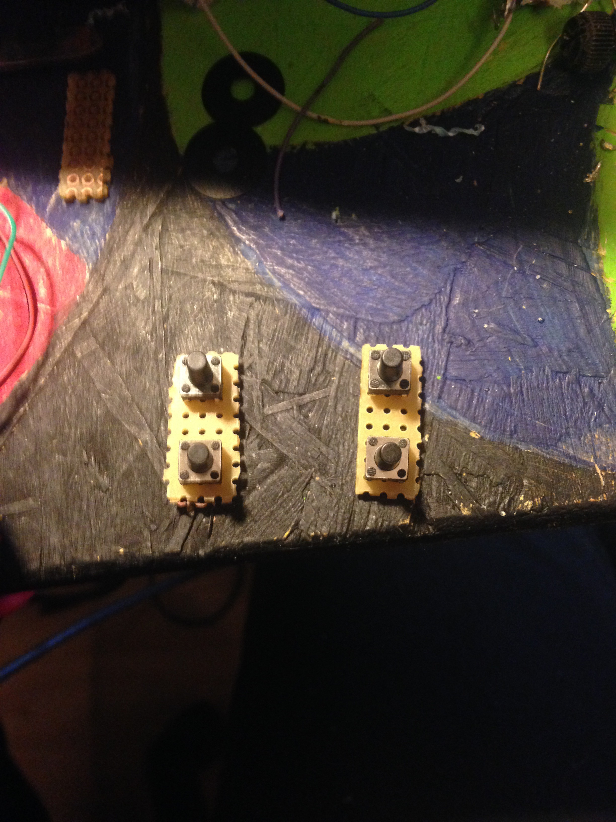
Adding the button PCB and the buttons
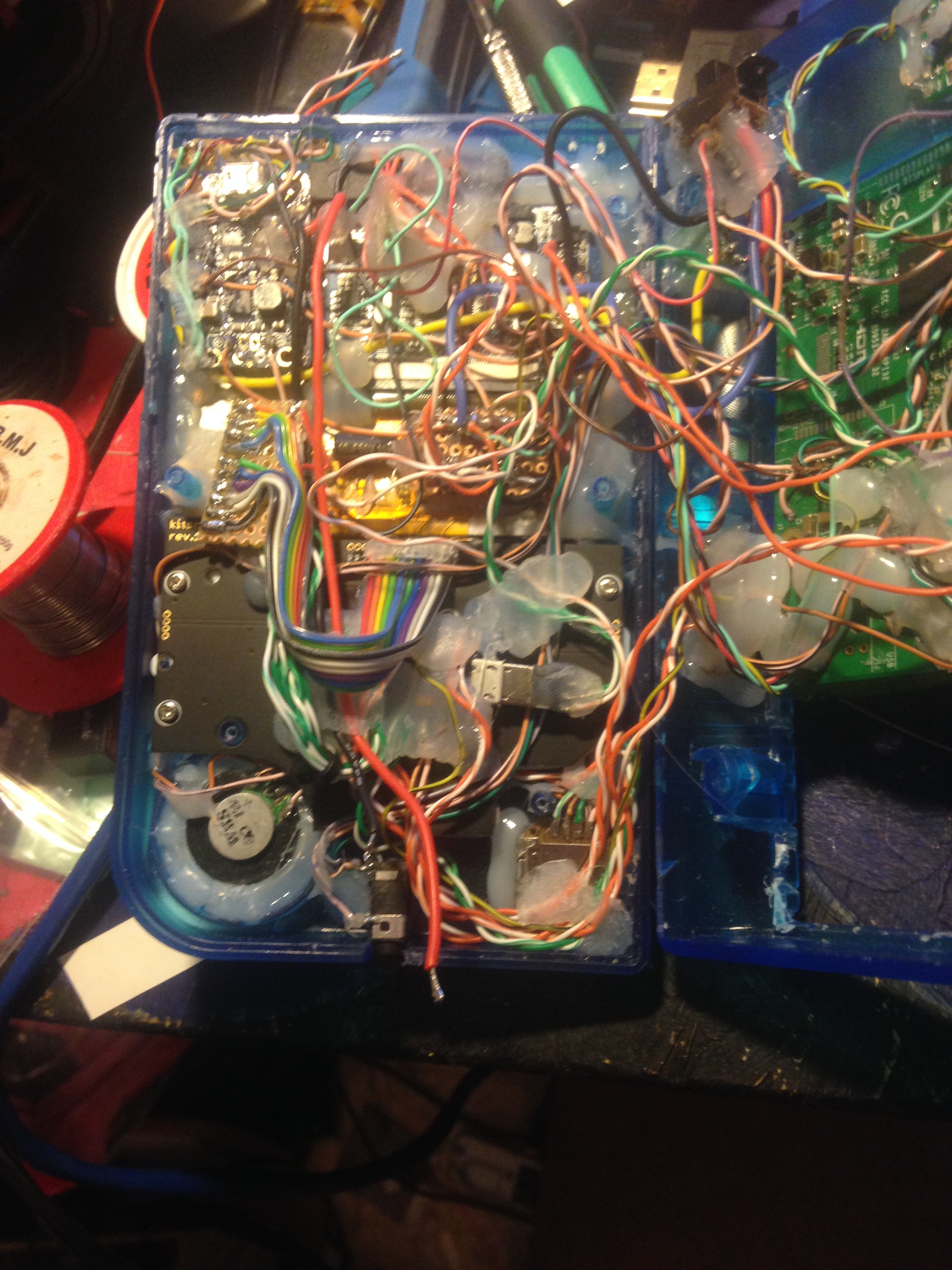
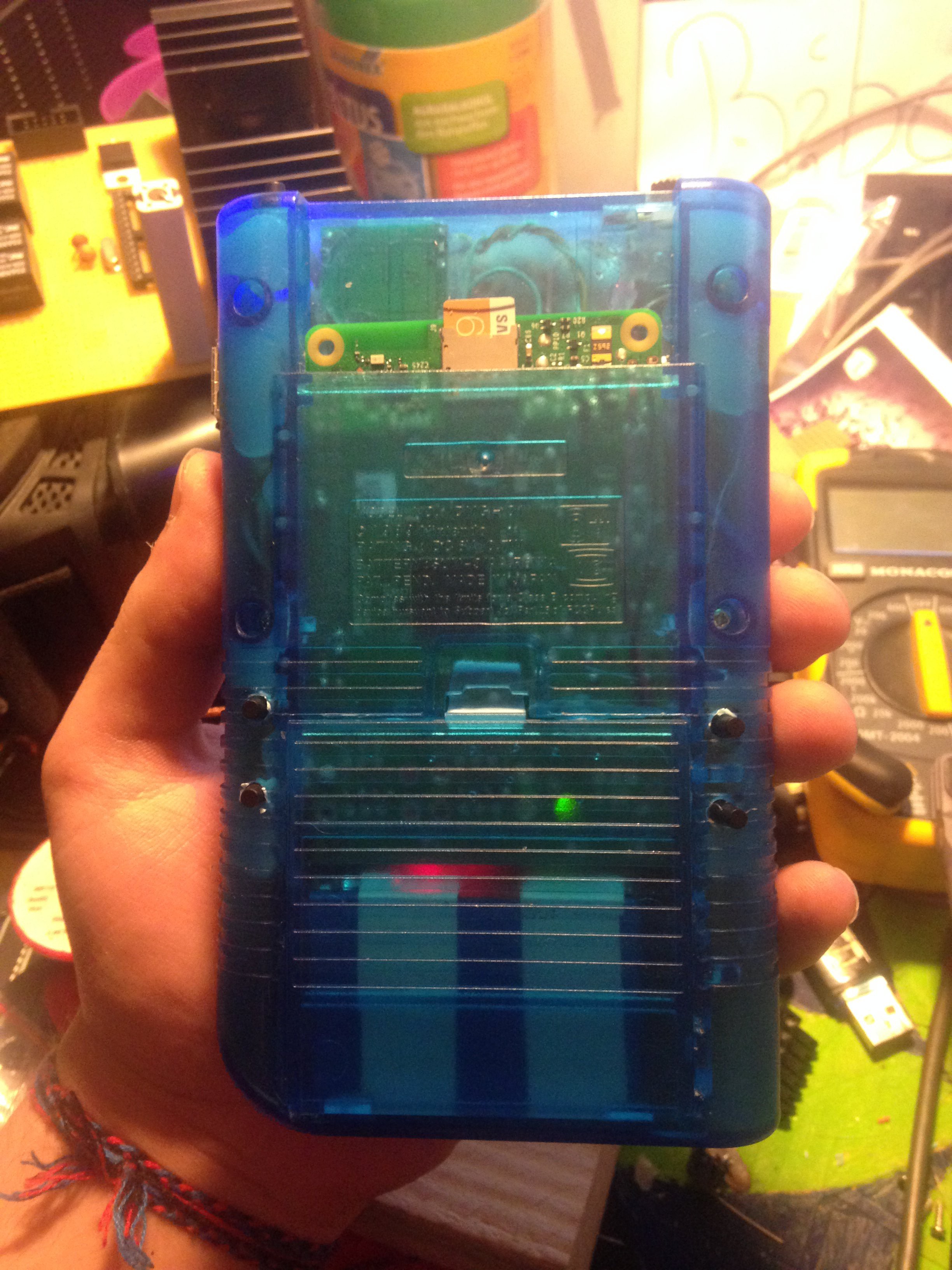
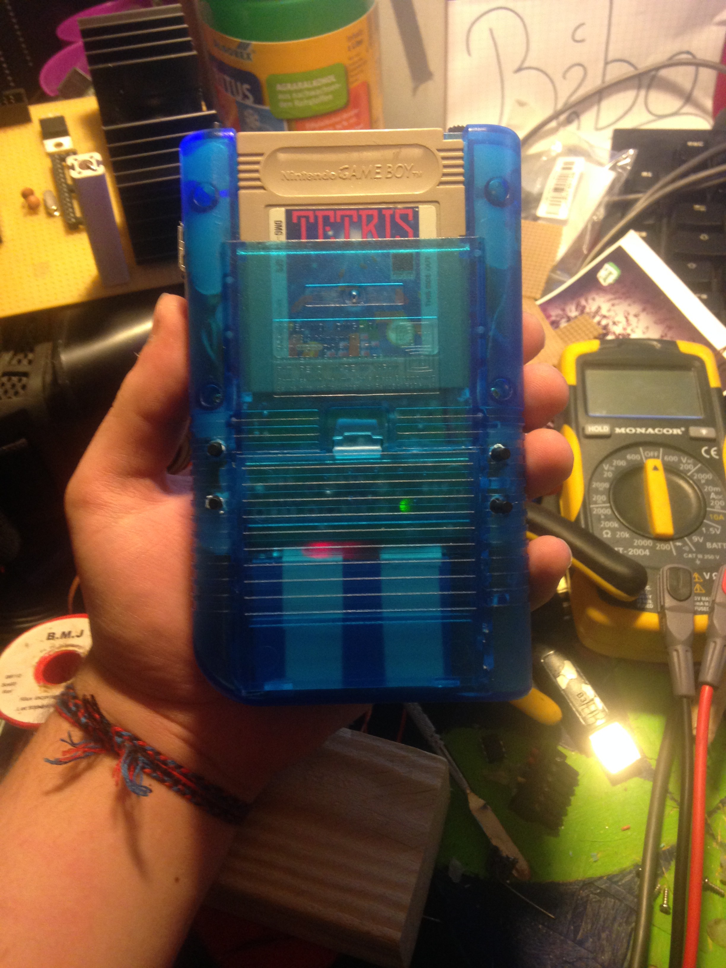
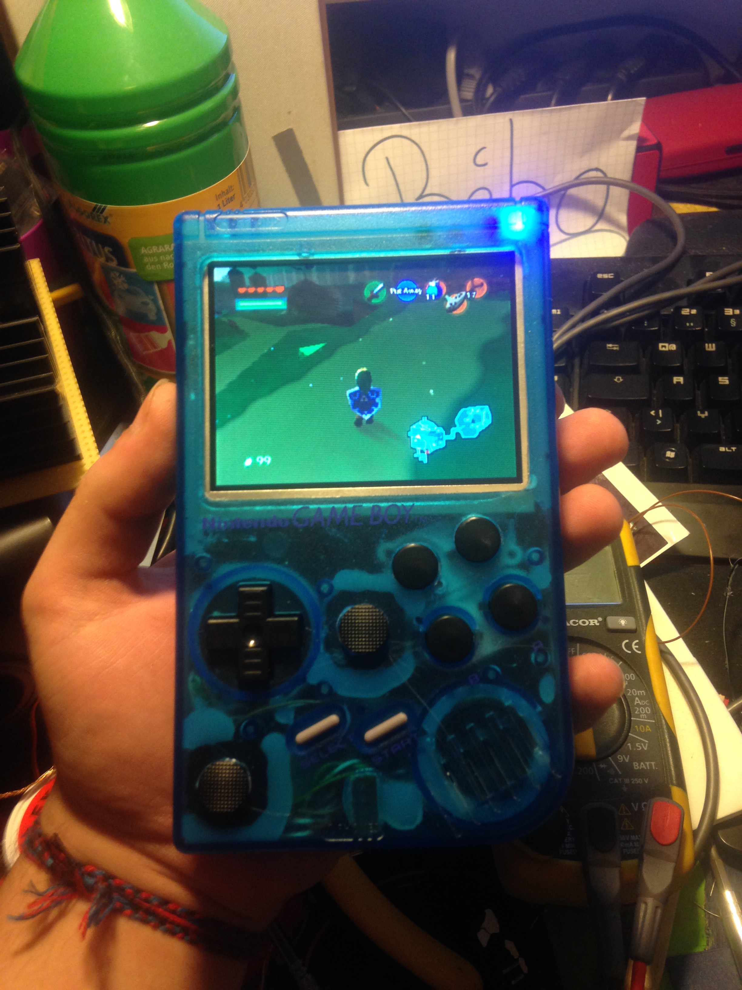
11/07/2016 at 23:17 • 0 commentsAll that is left out now are the front buttons. These are simply soldered to the leonardo micro, and that was it. As the sketch is already pre-programmed to work with buttons, no additional programming is neccessary. After that, I closed the gameboy and it was finished!
![]()
![]()
![]()
![]()
-
Adding a battery monitor with auto-shutdown
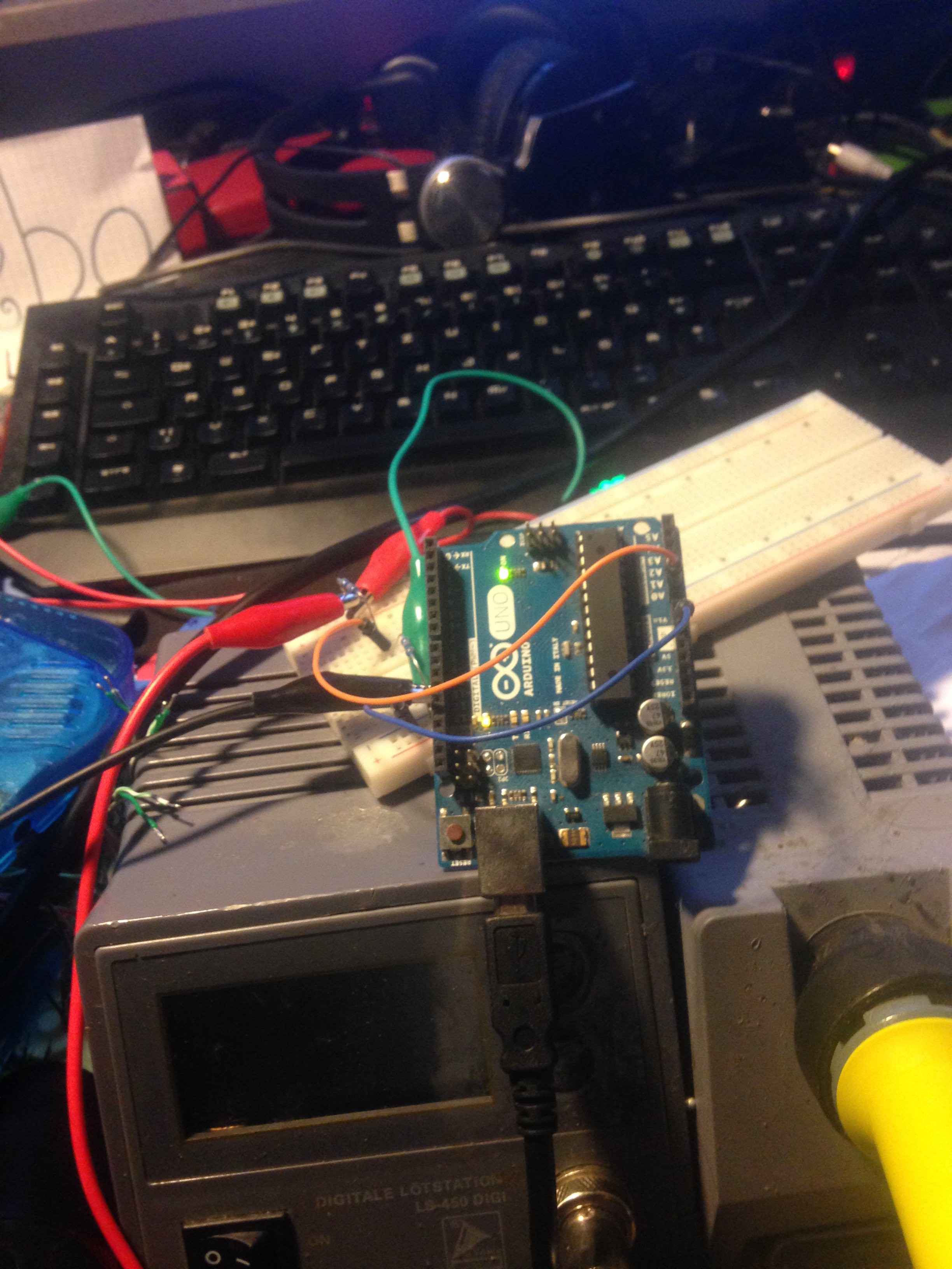
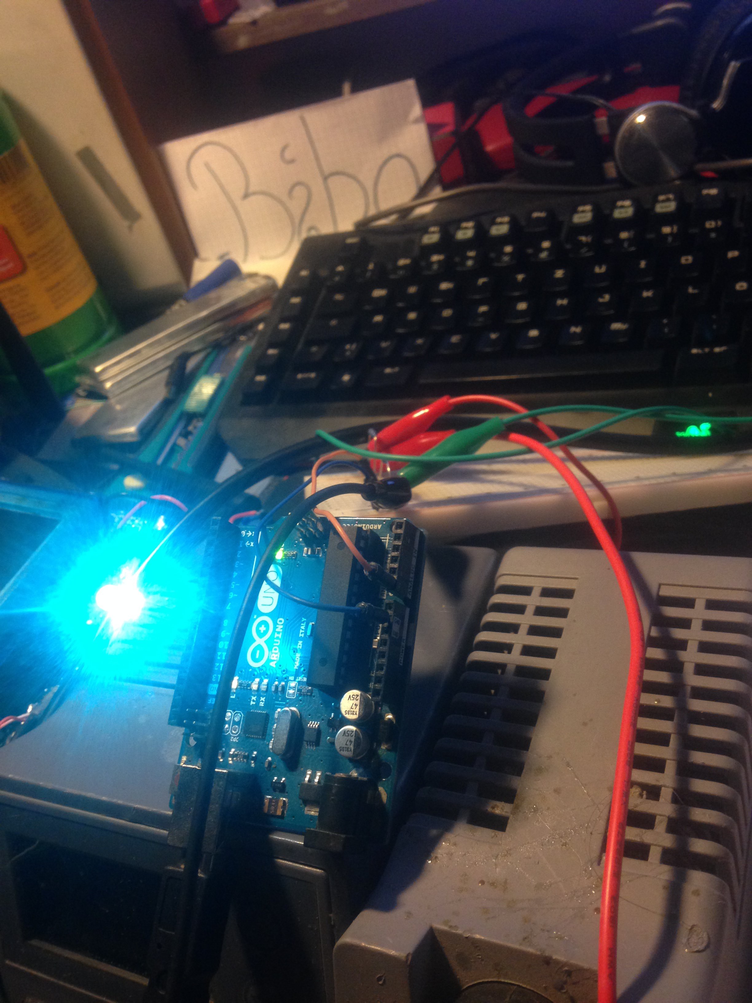
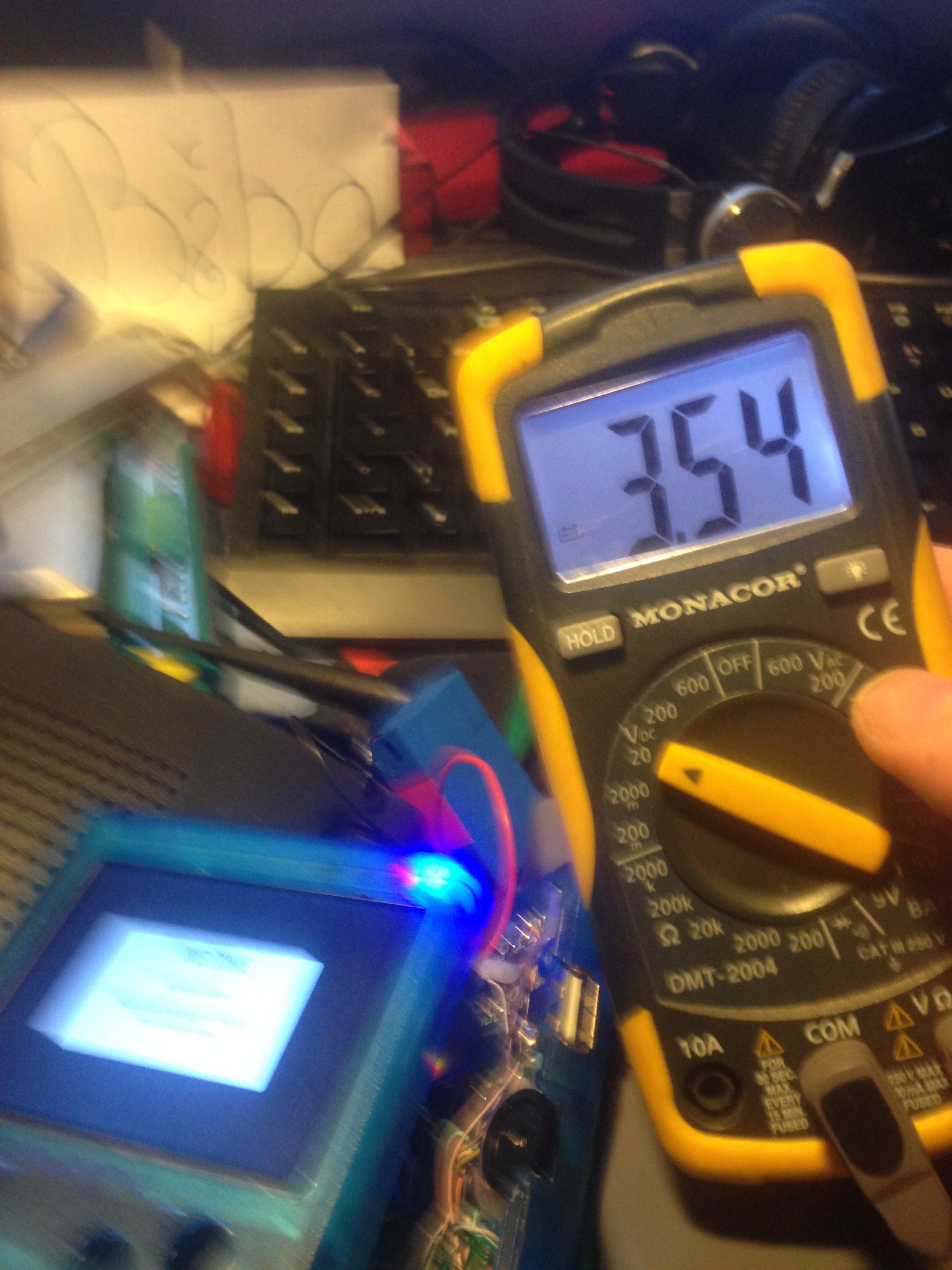
11/07/2016 at 22:59 • 0 commentsI took an Arduino UNO, and turned it into a low battery indicator as well as an automatic safe-shutdown circuit when the battery is too low. For that, connected everything on a breadboard and used a lab bench power supply to simulate a battery and get my readings I needed. I got my voltages by recording a video of me playing on a full battery untill my battery was totaly flat, so I could see at what minutes it is safe to shutdown and 10 minutes before that it is safe to say that the battery is almost done for.
My battery lasts for around 2 hours and 11 minutes in total.
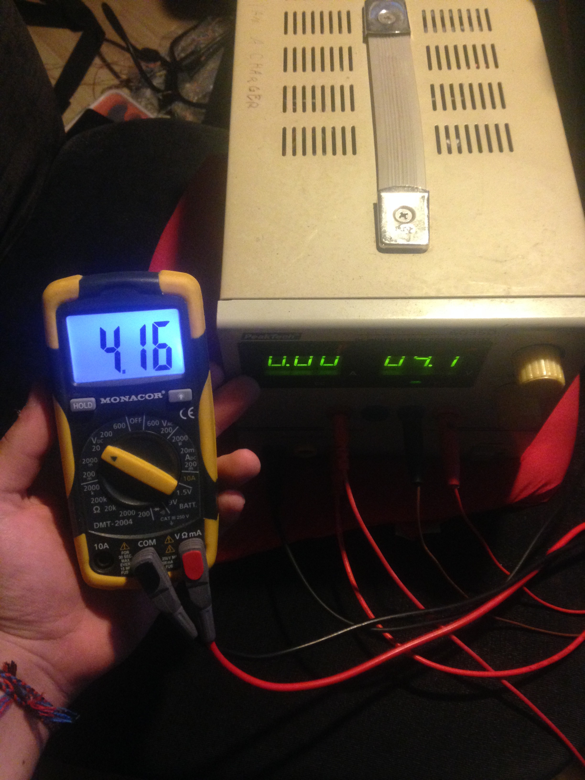
My readings are:
Battery full: ~4.16 Volt (not needed, though)
Battery low alert (red LED): ~3.54 Volt
Battery empty, need to shutdown NOW: ~3.20 Volt
![]()
![]()
![]()
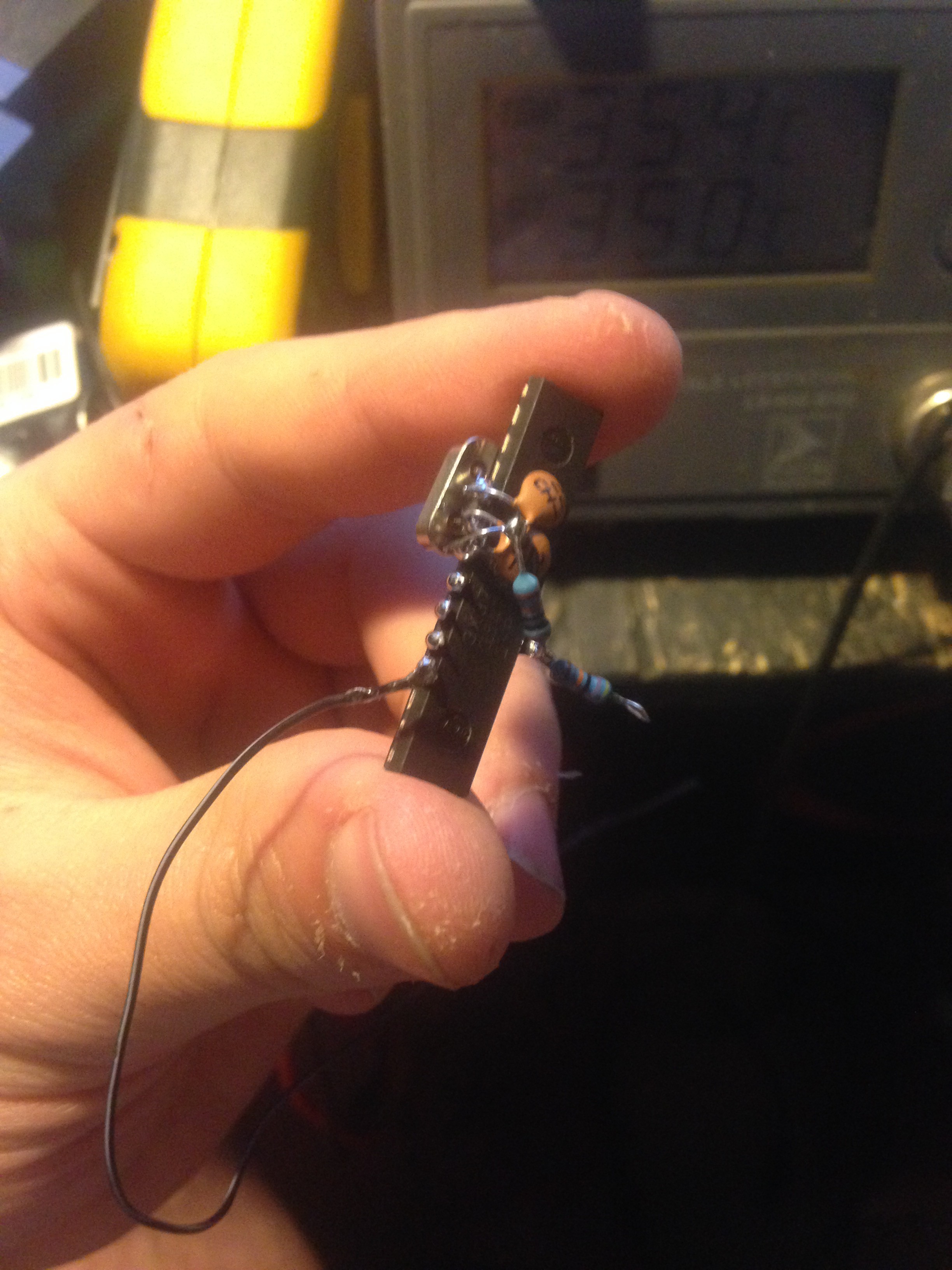
After everything was working, I made my arduino smaller by just using the atmega as itself with a quartz, and a voltage divider as battery input and checked that everything works like that:
![]()
![]()
-
Gluing in the analog sticks and programming the leonardo pro micro
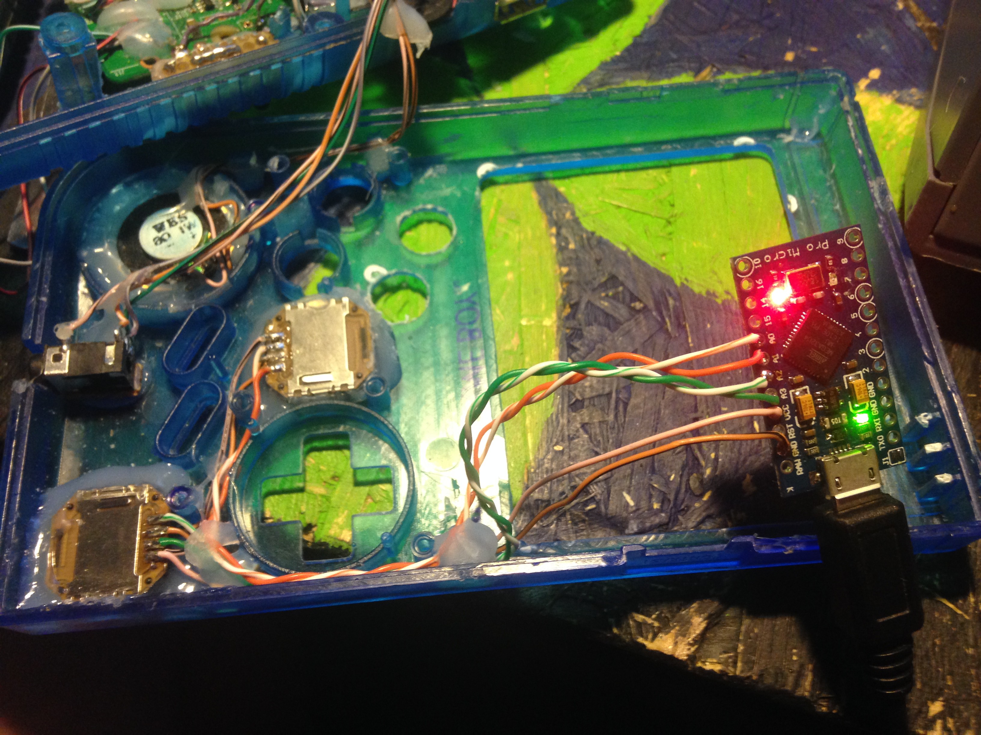
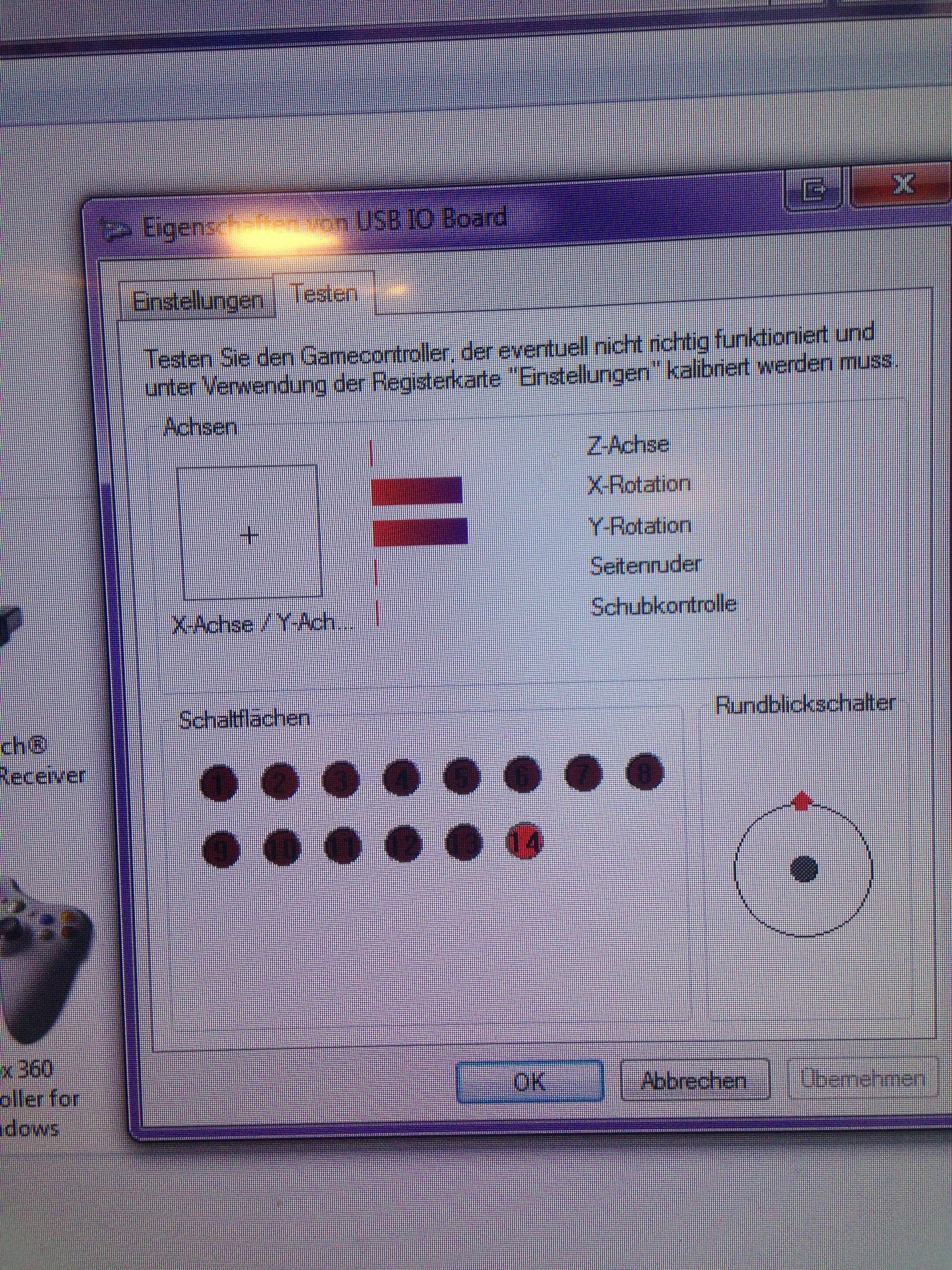
11/07/2016 at 22:26 • 0 commentsI glued in the analog sticks and soldered the corresponding wires to them. I then wrote a program to turn the leonardo into a USB joystick with 14 buttons and two analog inputs and fiddled around a little to get my code working with those analog sticks.
![]()
![]()
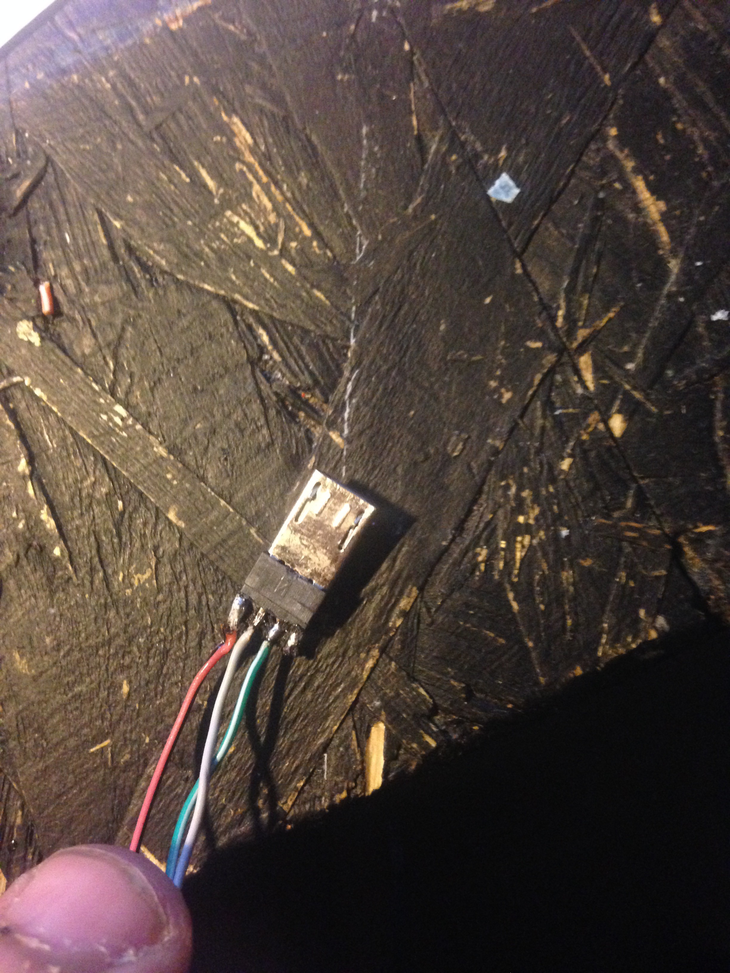
Also, to connect the pi to the leonardo later on, I took an cheap, broken µUSB cable, and got the µUSB part of it and soldered the wires coming from the pi to for easy plugging in:
![]()
-
Adding shoulder buttons
11/07/2016 at 22:17 • 0 commentsI soldered 2 tactile switches to a small piece of perfboard, and then made another one for the other side. These will be my L1, L2, R1 and R2 switches. Afterwards, I glued them in and soldered wires accordingly.
![]()
![]()
-
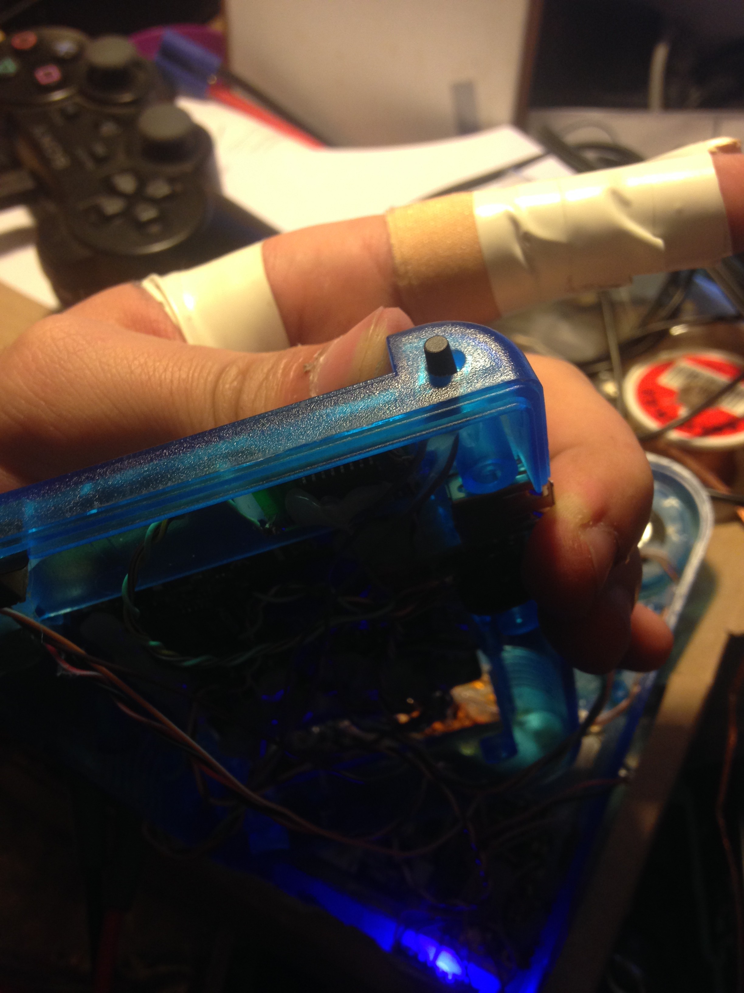
Adding a safe shutdown switch
11/07/2016 at 21:40 • 0 commentsNext up is to add a tactile switch in the upper right to make the pi safely shutdown when this switch is held for 1 second.
![]()
the switch is closing GND to GPIO pin 37.
-
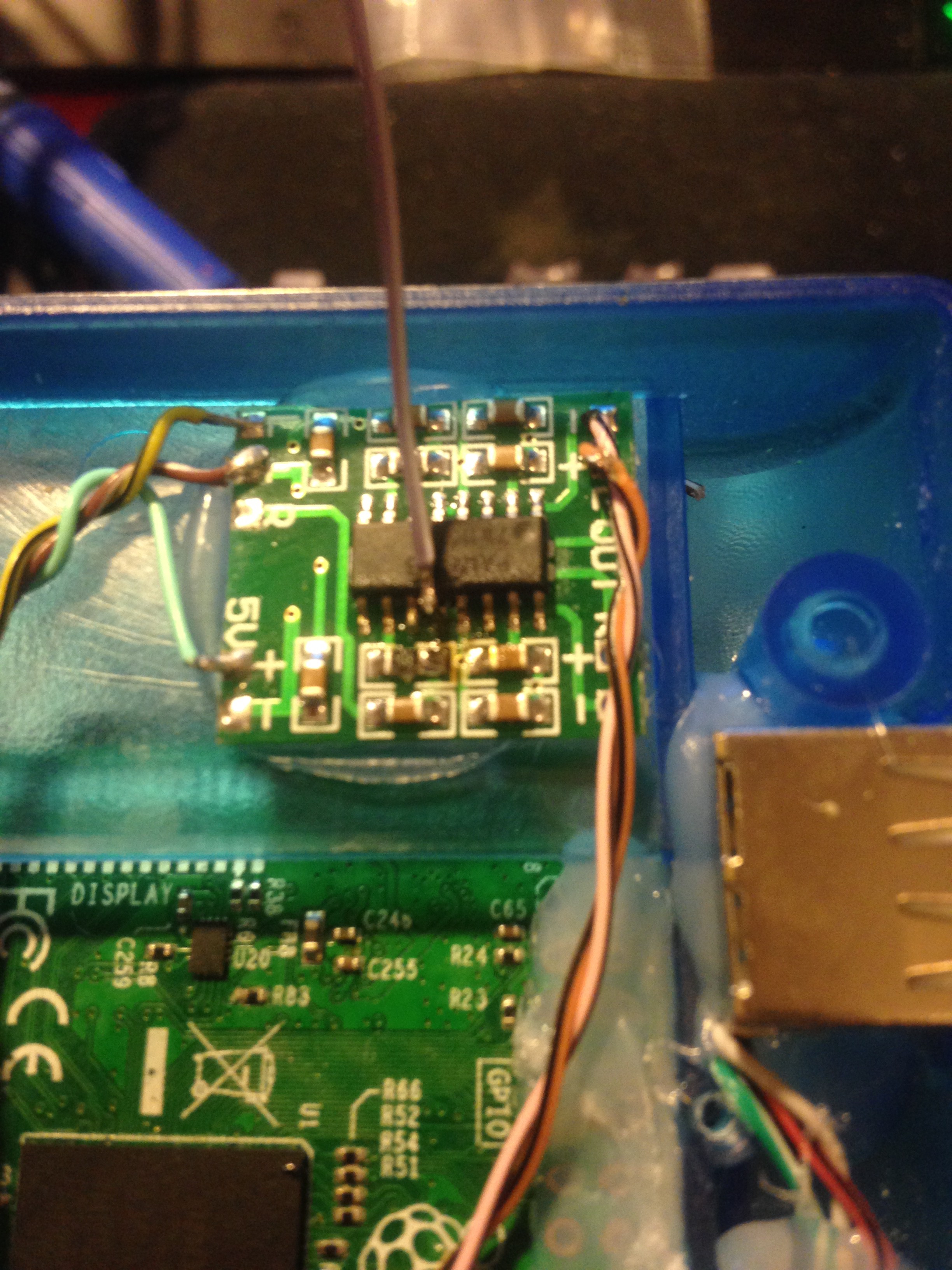
Wiring up the amp and heaphone jack
11/07/2016 at 21:31 • 0 commentsNext up is the audio amplifier, speaker, potentiometer and the headphone jack
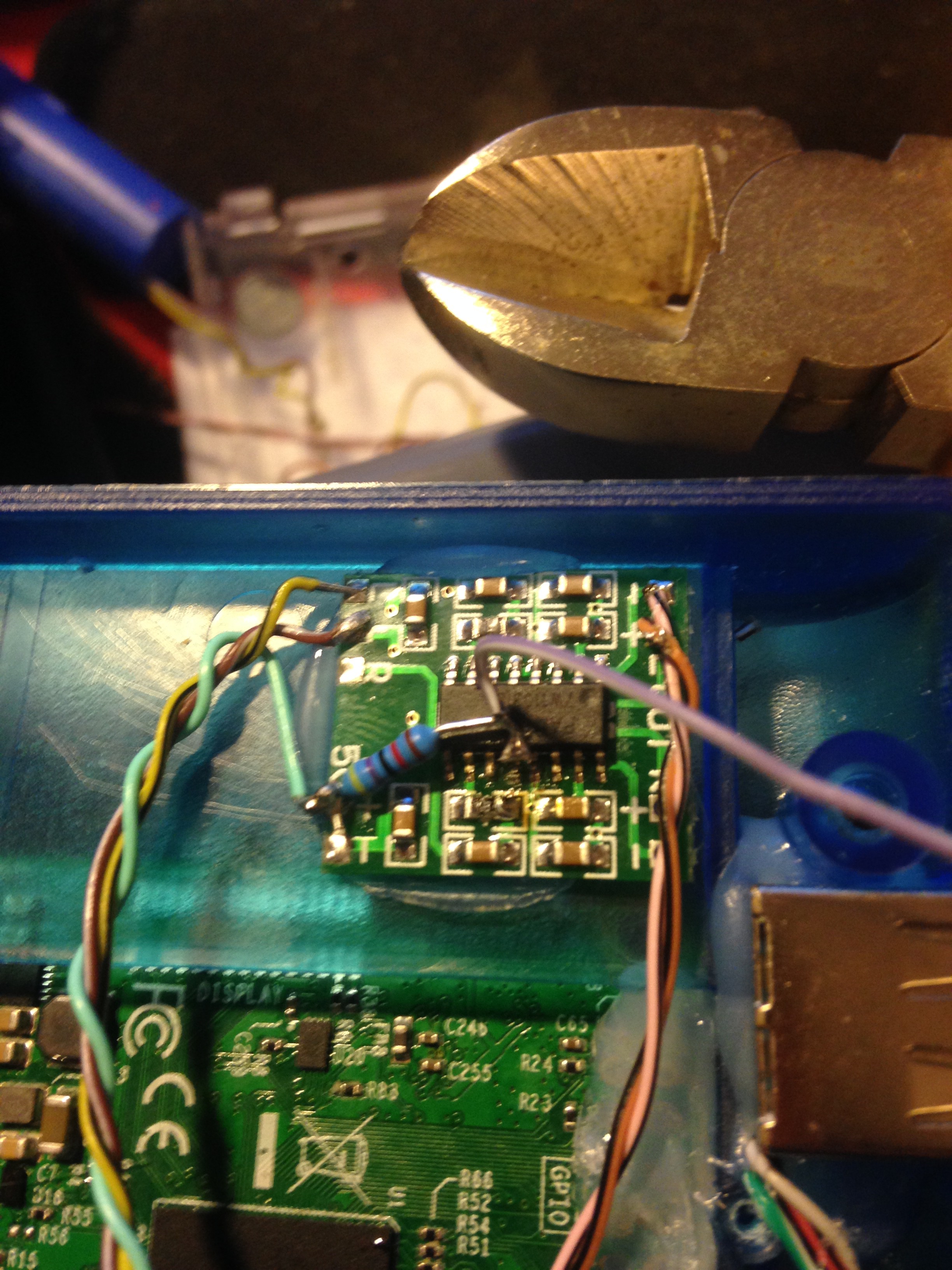
The amplifier has to be modified a little bit in order for it to shut down when headphones are plugged in.
For that, pin 12 needs to be desoldered from the board, and a wire soldered to it. It is the shutdown pin. We need to solder on a 10K or 20K pullup resistor to it and VCC, or the amp will stay off all the time:
![]()
![]()
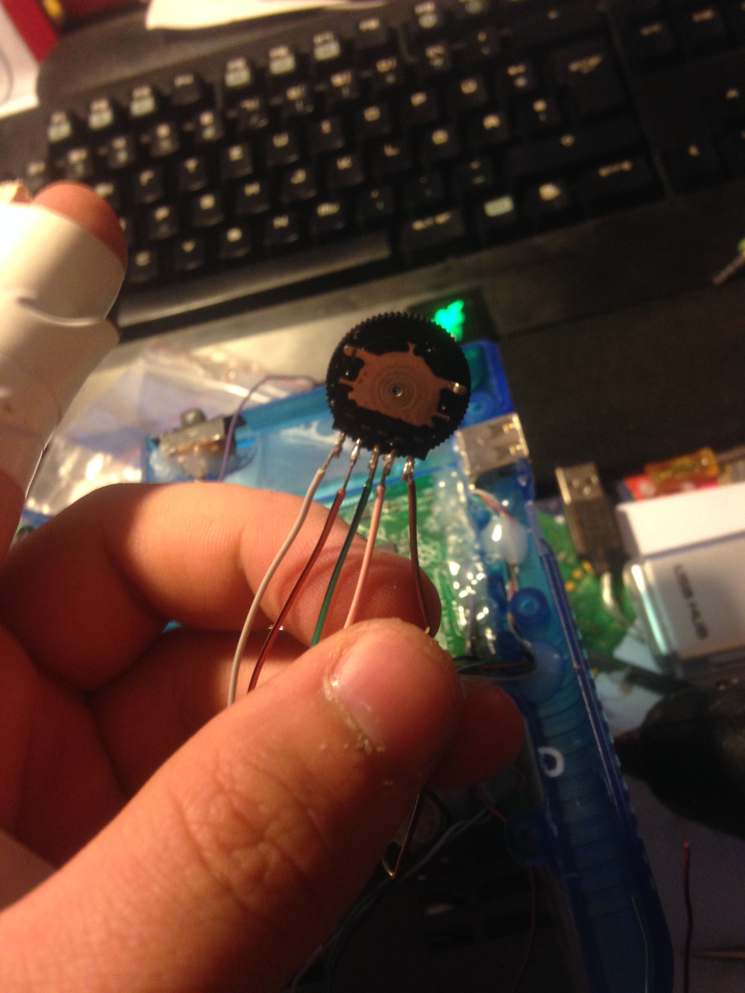
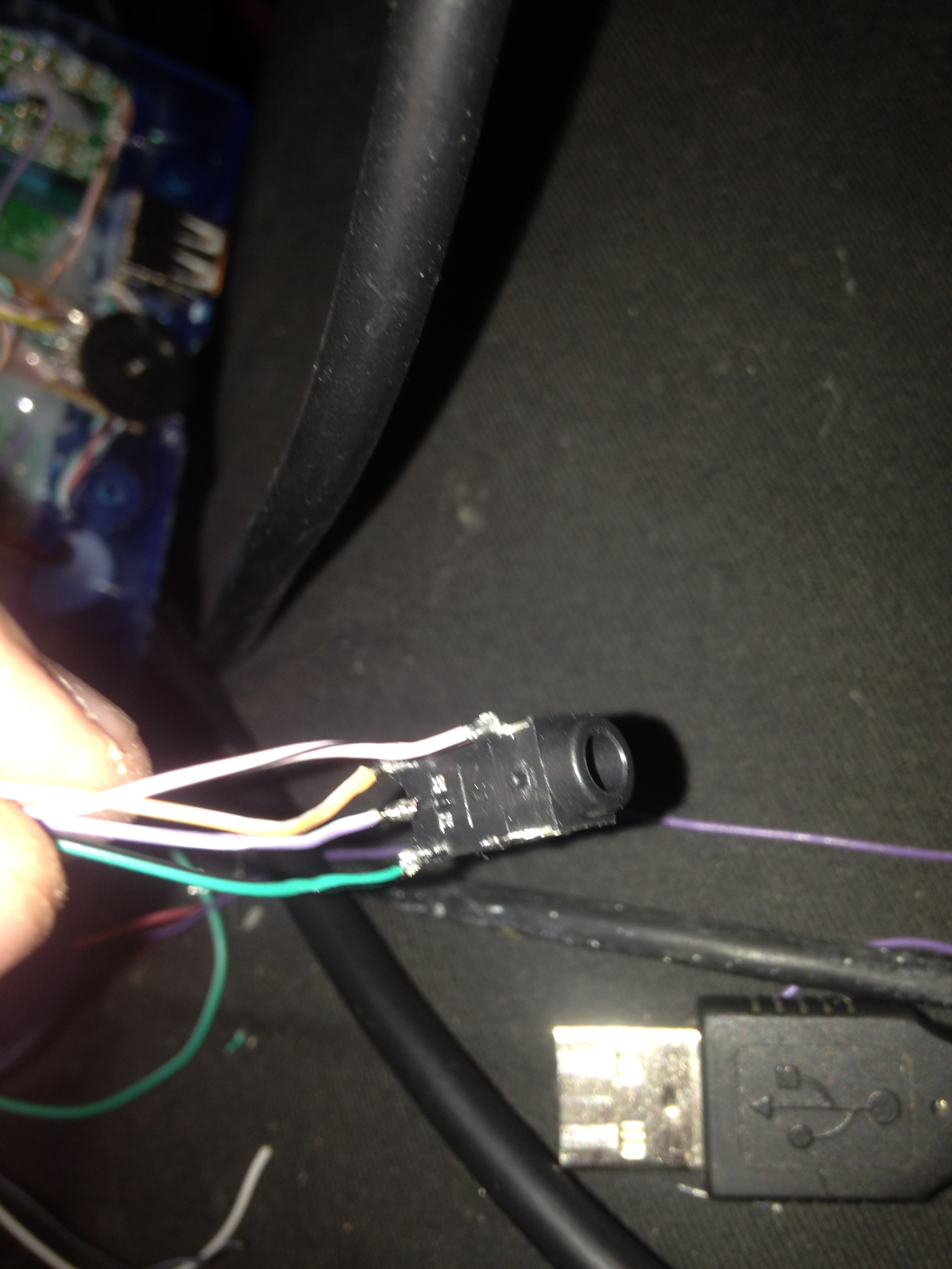
Then the potentiometer is wired to the pi, the amp and the headphone jack:
![]()
![]()
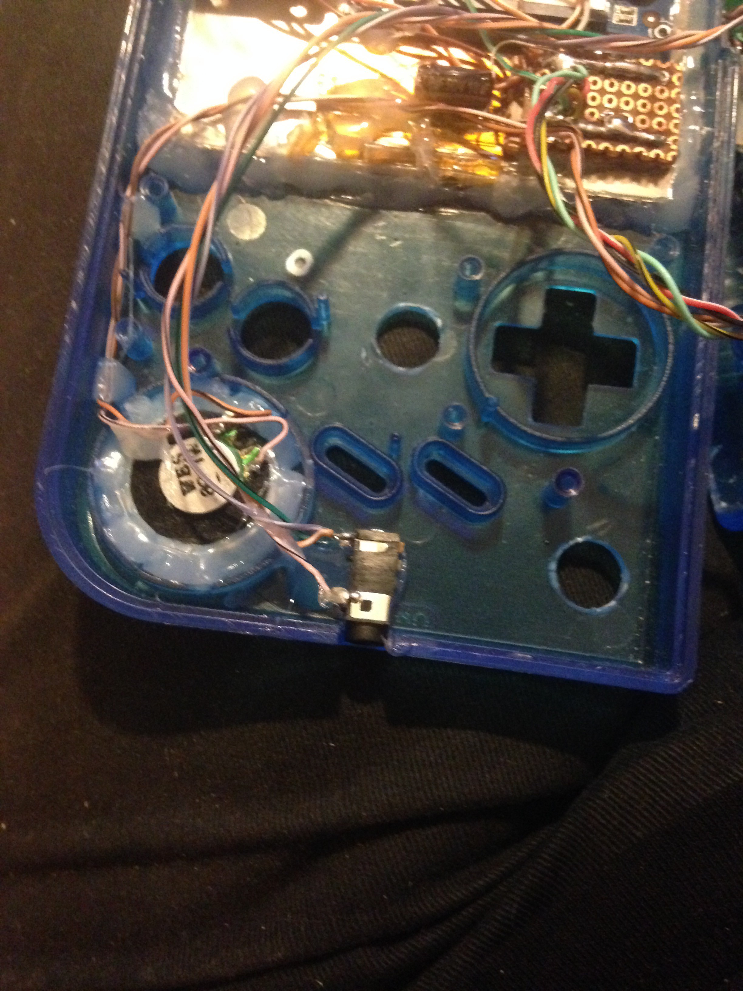
And then I wired the speaker to the amp and glued everything in place:
![]()
![]()
-
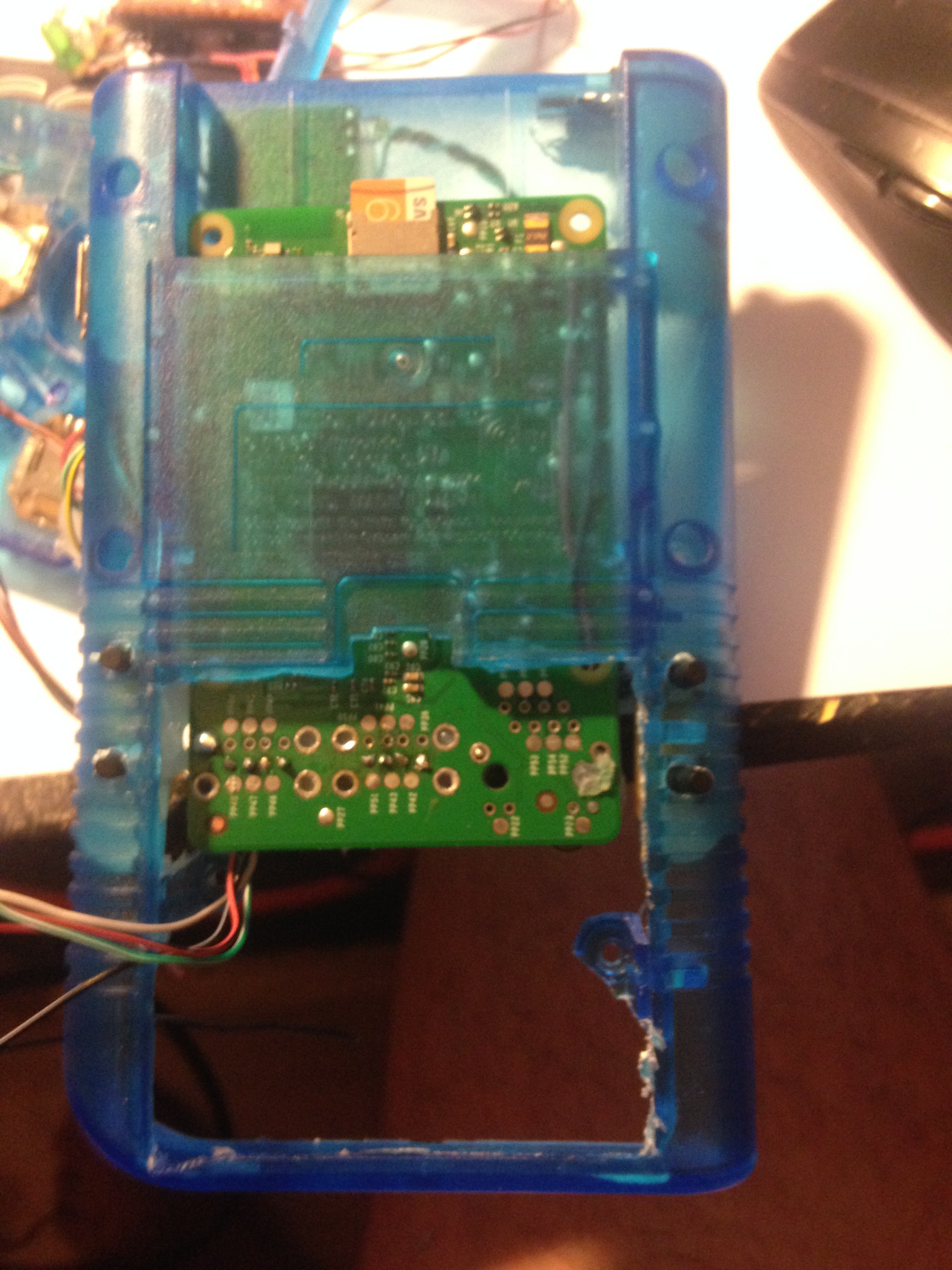
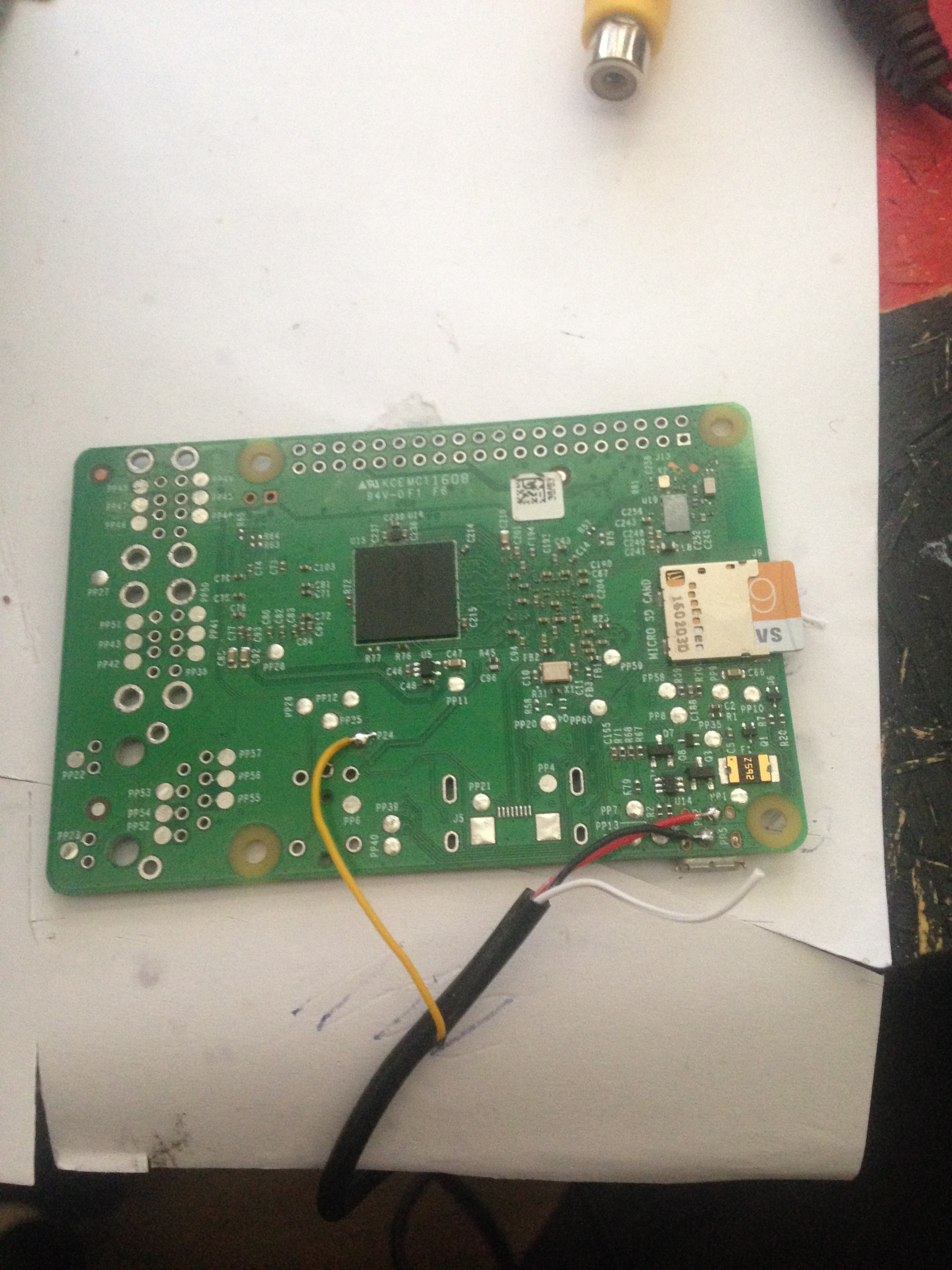
Soldering on wires to the Pi and gluing it in
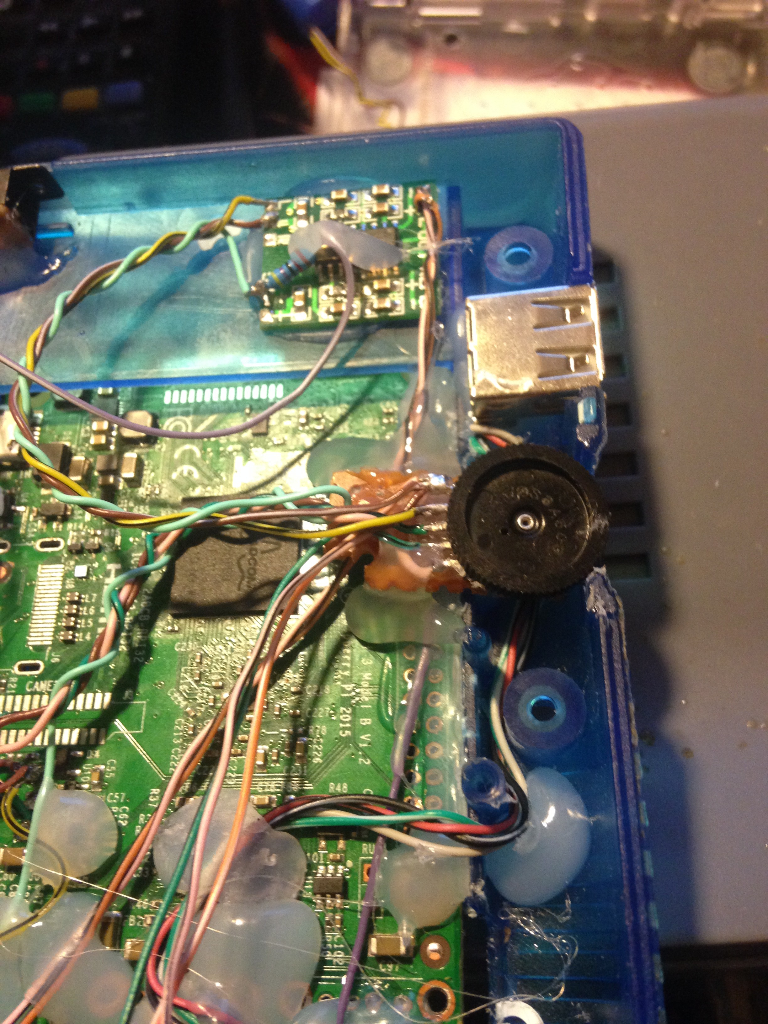
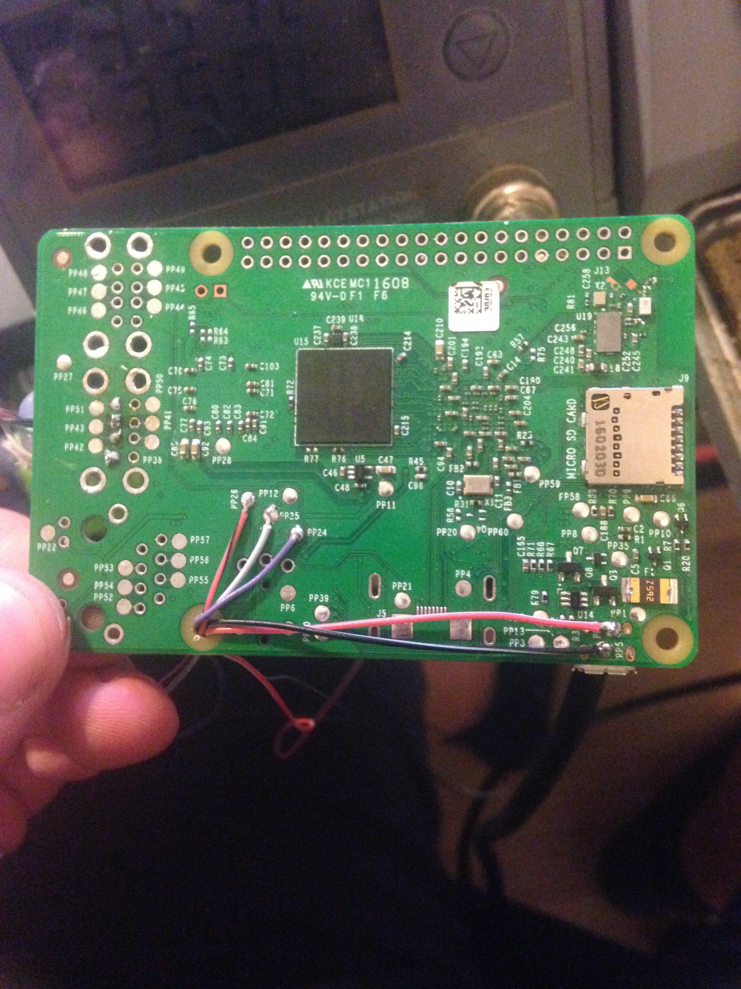
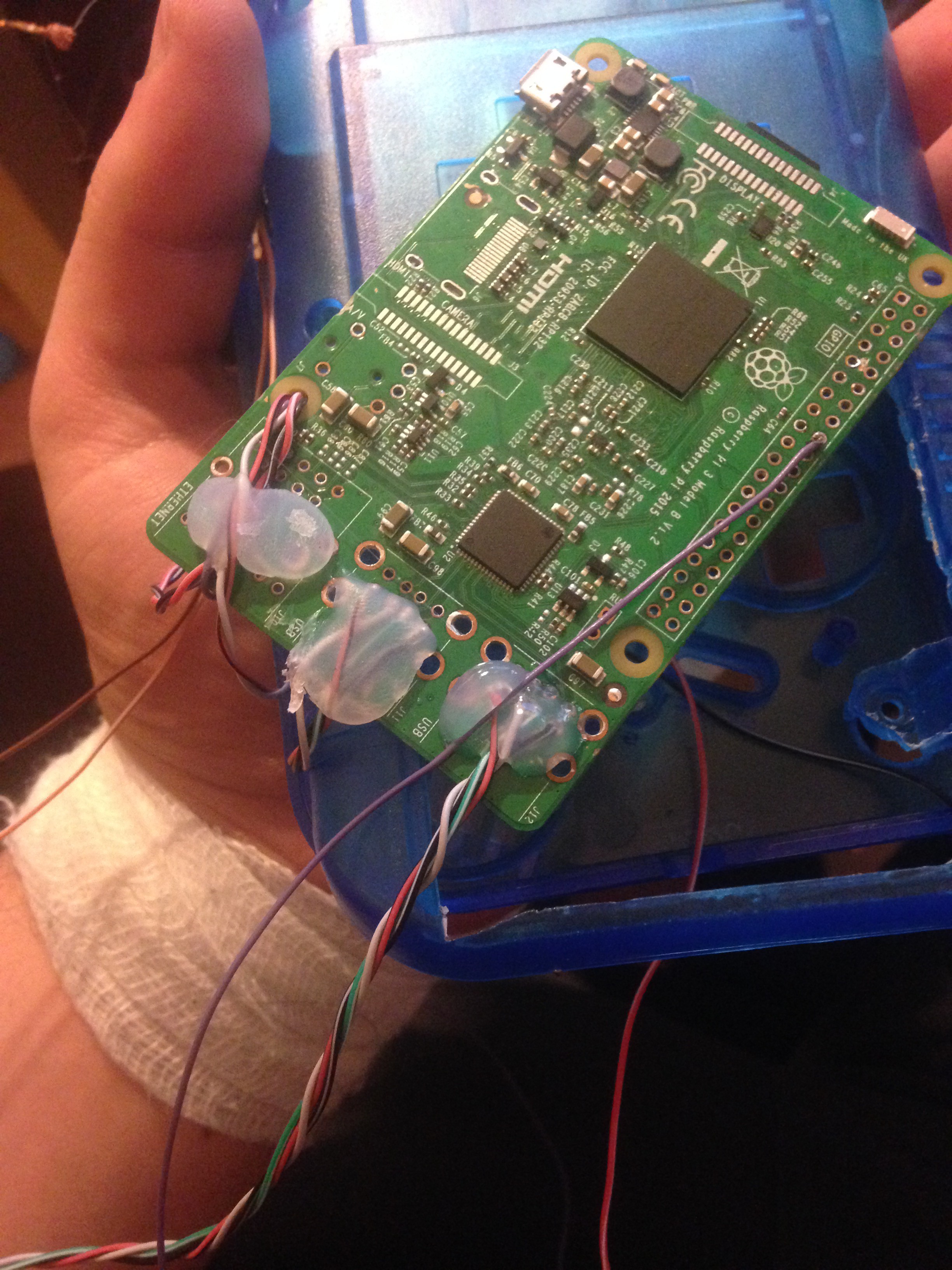
11/07/2016 at 20:58 • 0 commentsI began soldering wires to the power input of the Pi, audio and video and soldered in 2 sets of 4 wires for USB. One will be used for the USB port, and the other for my leonardo pro micro:
![]()
I then also soldered in a wire to a GPIO pin which will be used to safe-shutdown the Pi later. I later on moved it to another pin not shown in this picture, though.
![]()
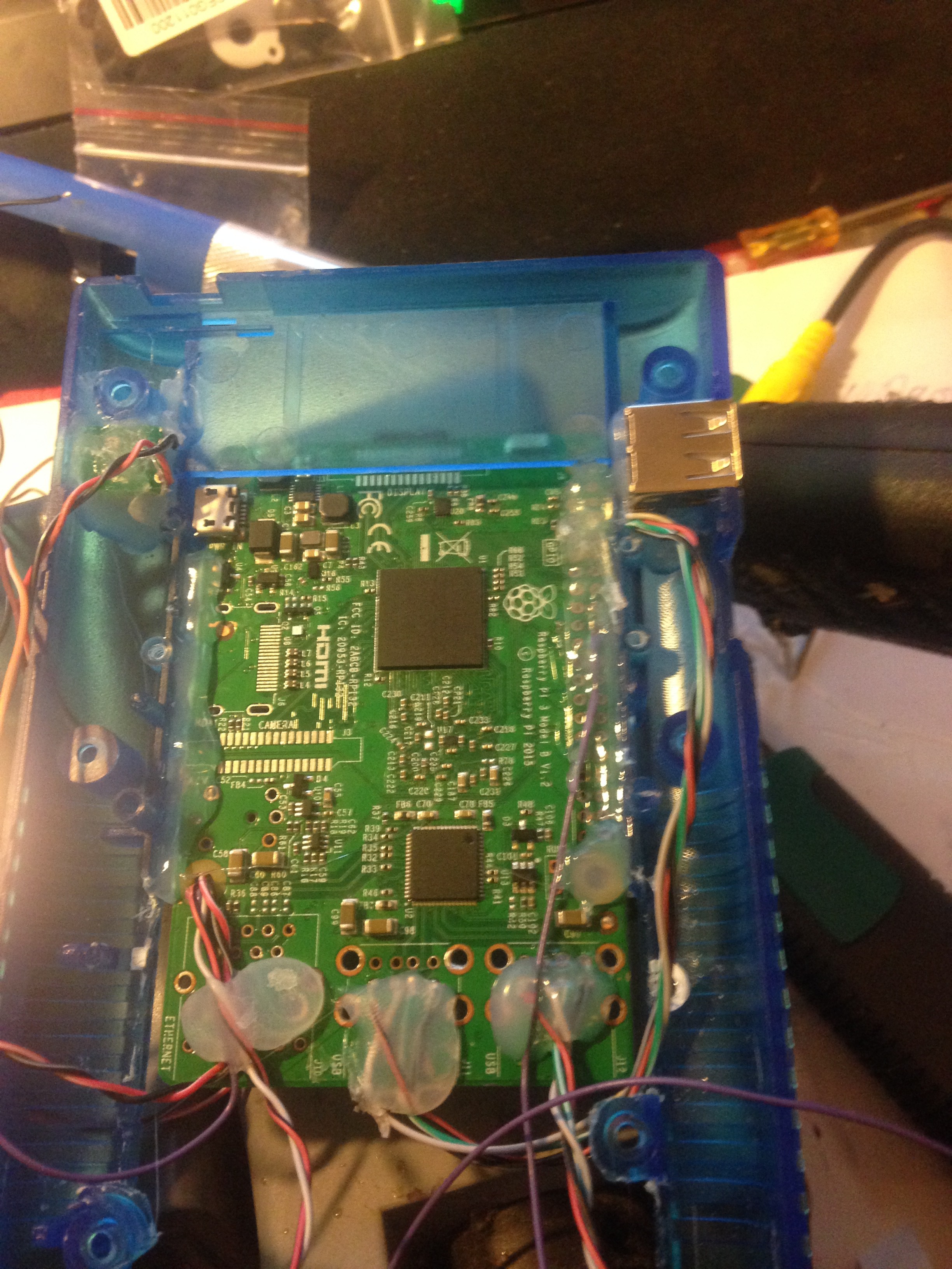
Then I finaly glued in the Pi in the cartridge slot, and the USB port also glued in:
![]()
-
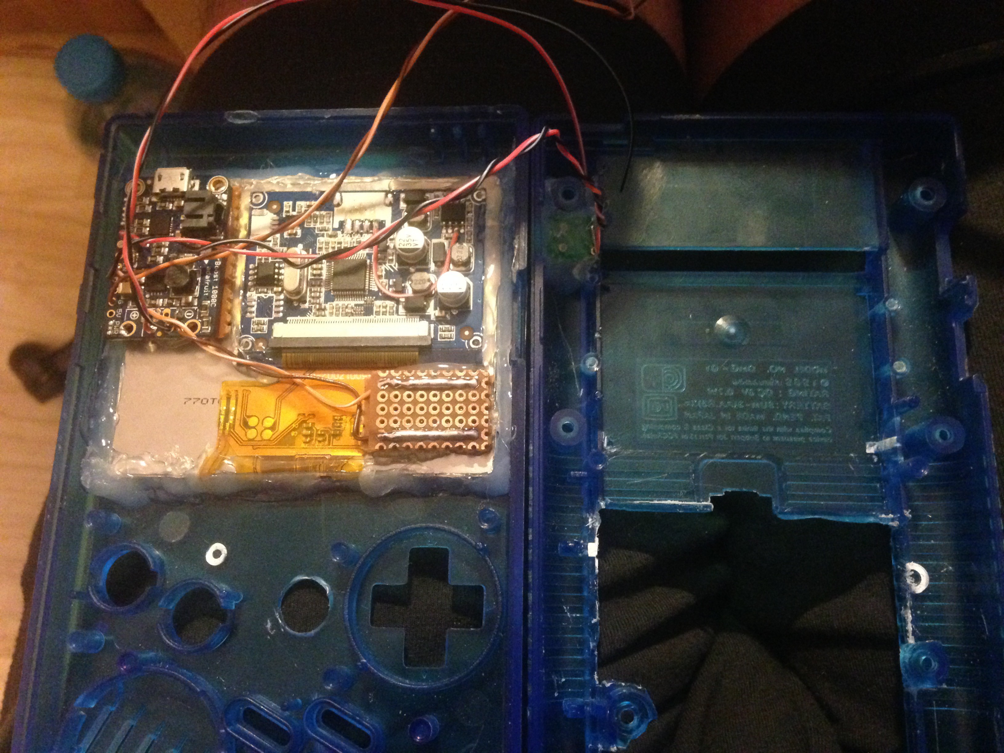
Gluing in the screen and some components
11/07/2016 at 20:39 • 0 commentsI glued in the screen in the place where it is supposed to go with it's controller (and a piece of paper underneath) and on top of that the powerboost with a piece of perfboard underneath to prevent shorts and the same for the power rail and wired everything up.
![]()
-
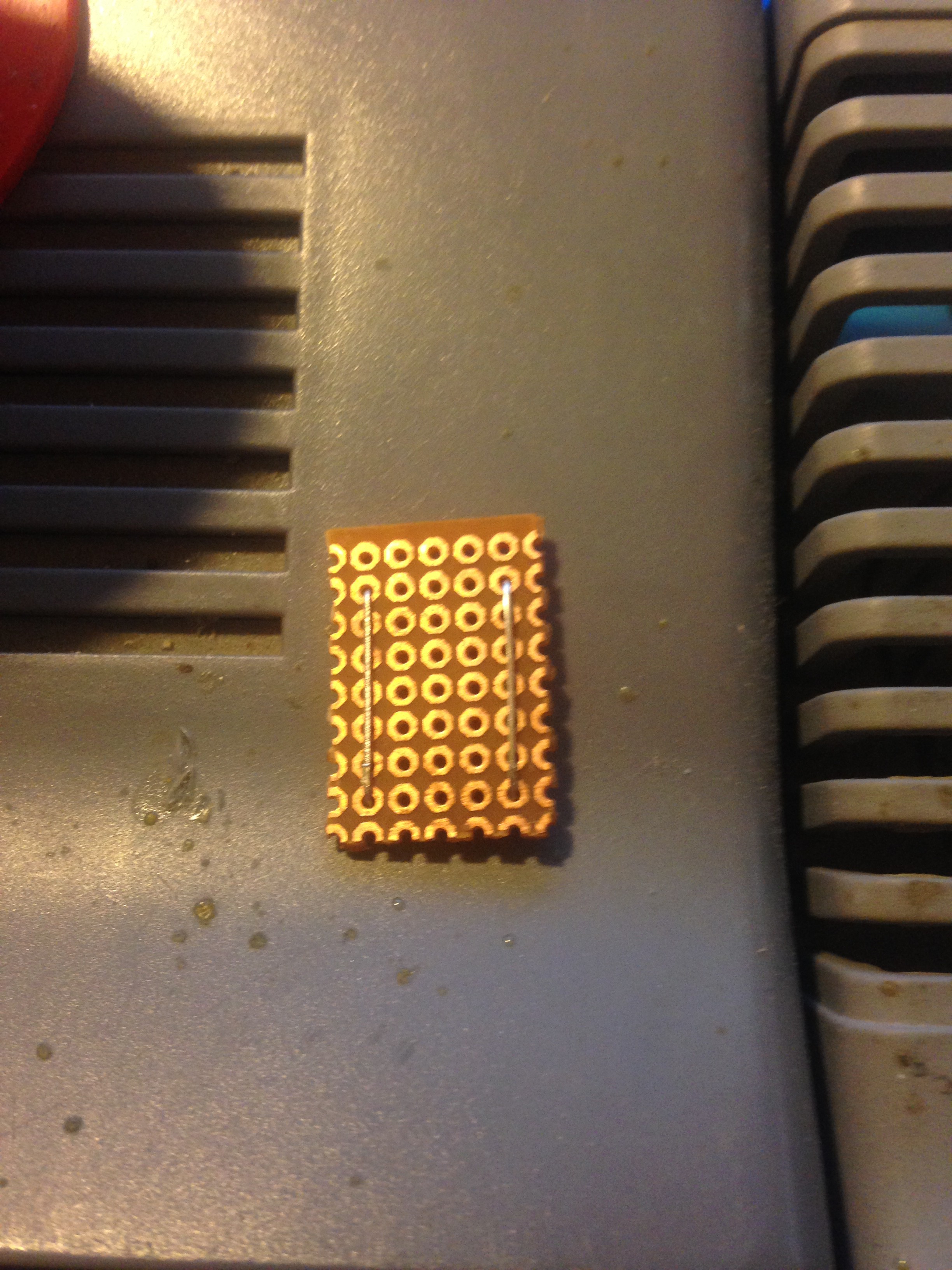
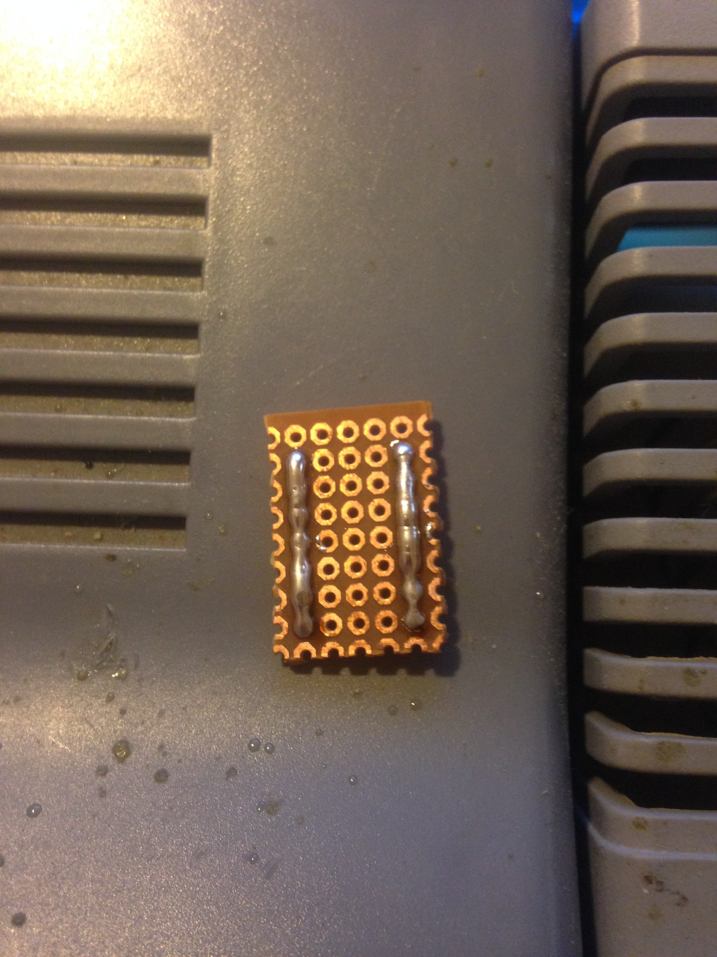
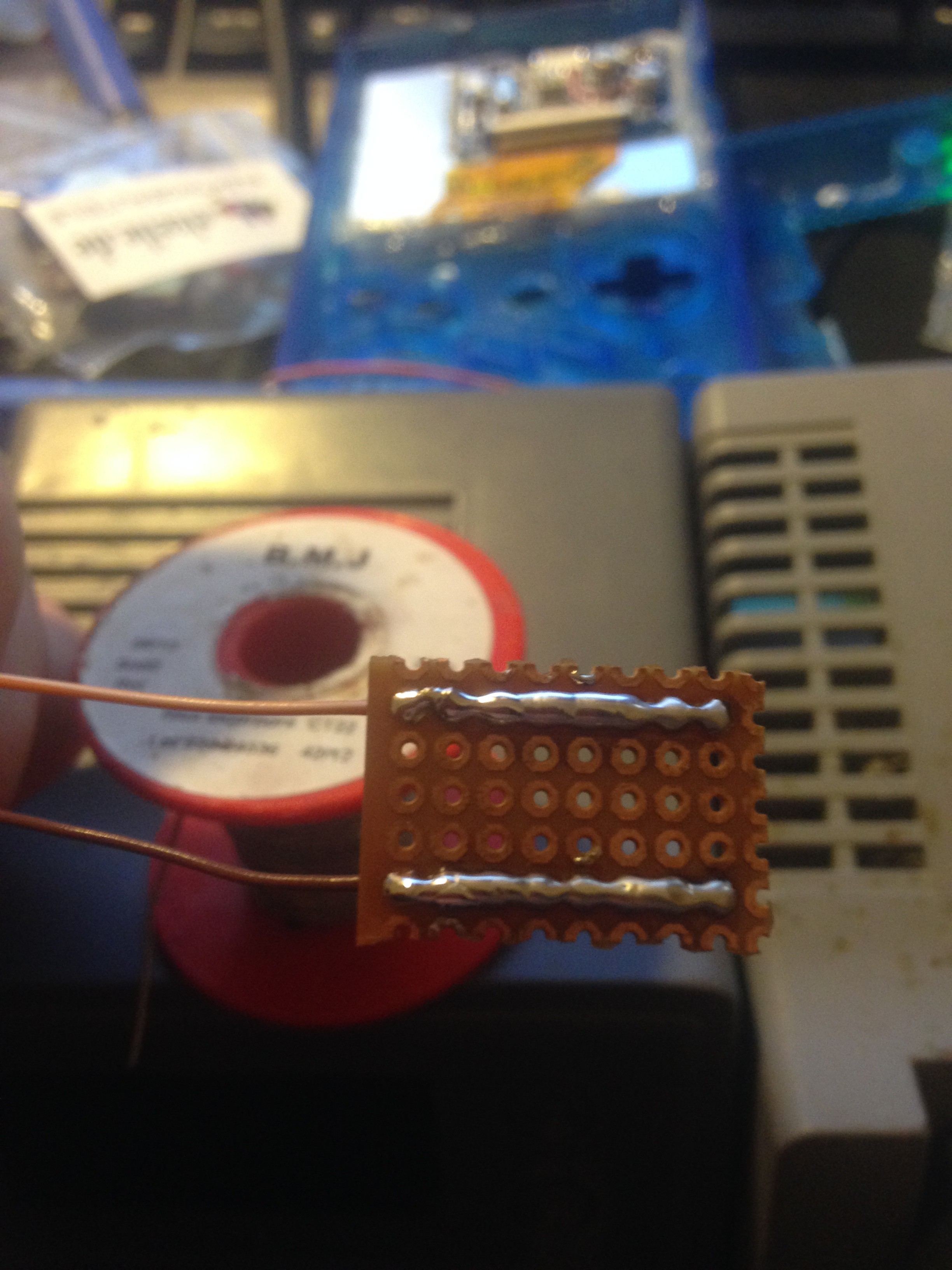
Making a small "power distributor"
11/07/2016 at 20:22 • 0 commentsI made a small "power distributor" for easier hook up for devices that need power. It is wired directly to the
powerboost's output. I made it out of perfboard:
![]()
![]()
![]()
-
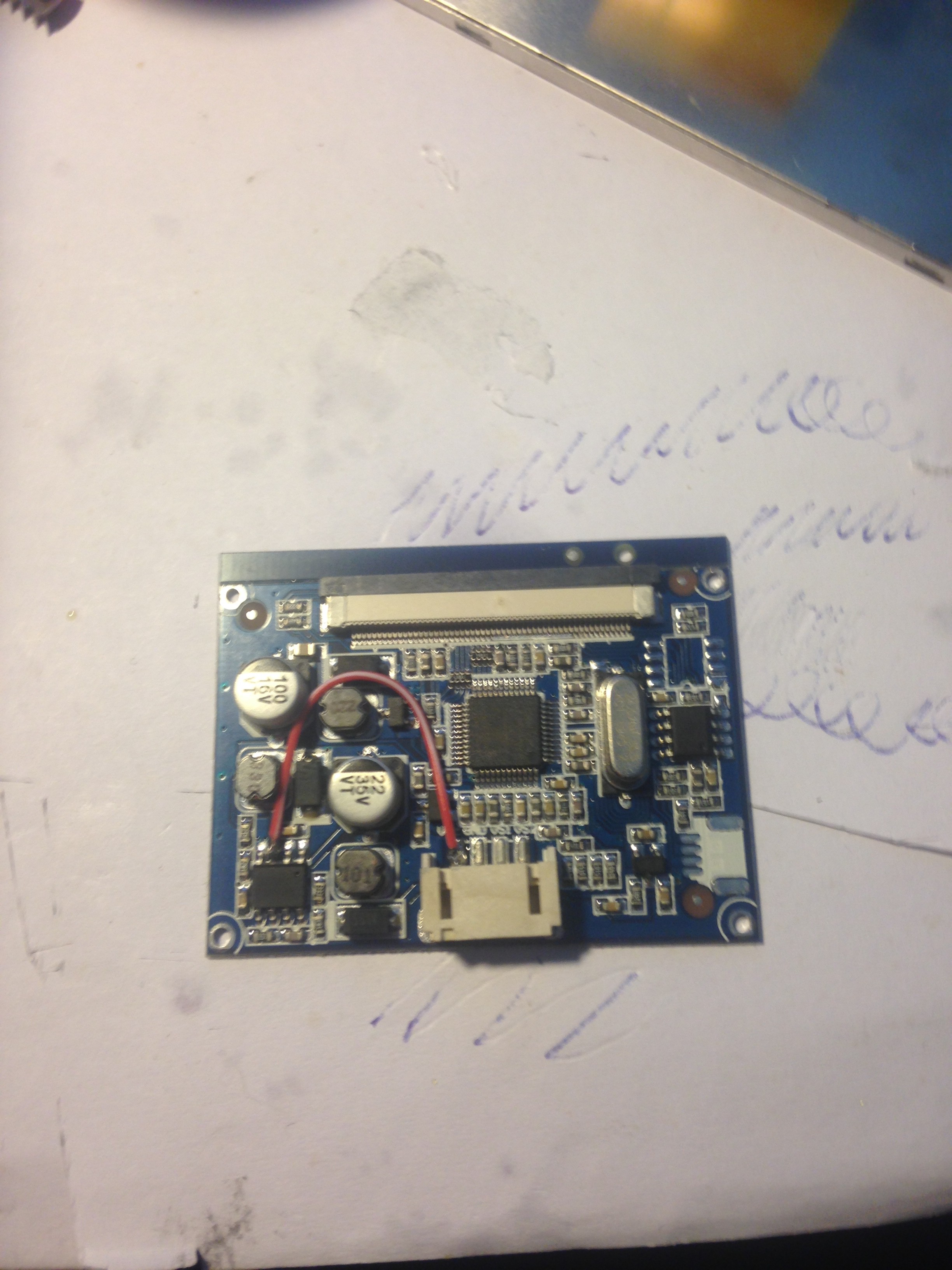
Modifying the screen to work with 5 Volts
11/07/2016 at 20:09 • 0 commentsThe screen won't work with 5 Volts out of the box, so it needs to be modified a litlle.
For that I soldered a wire to the power line and the 2nd pin of the power regulator IC and that does the trick:
![]()
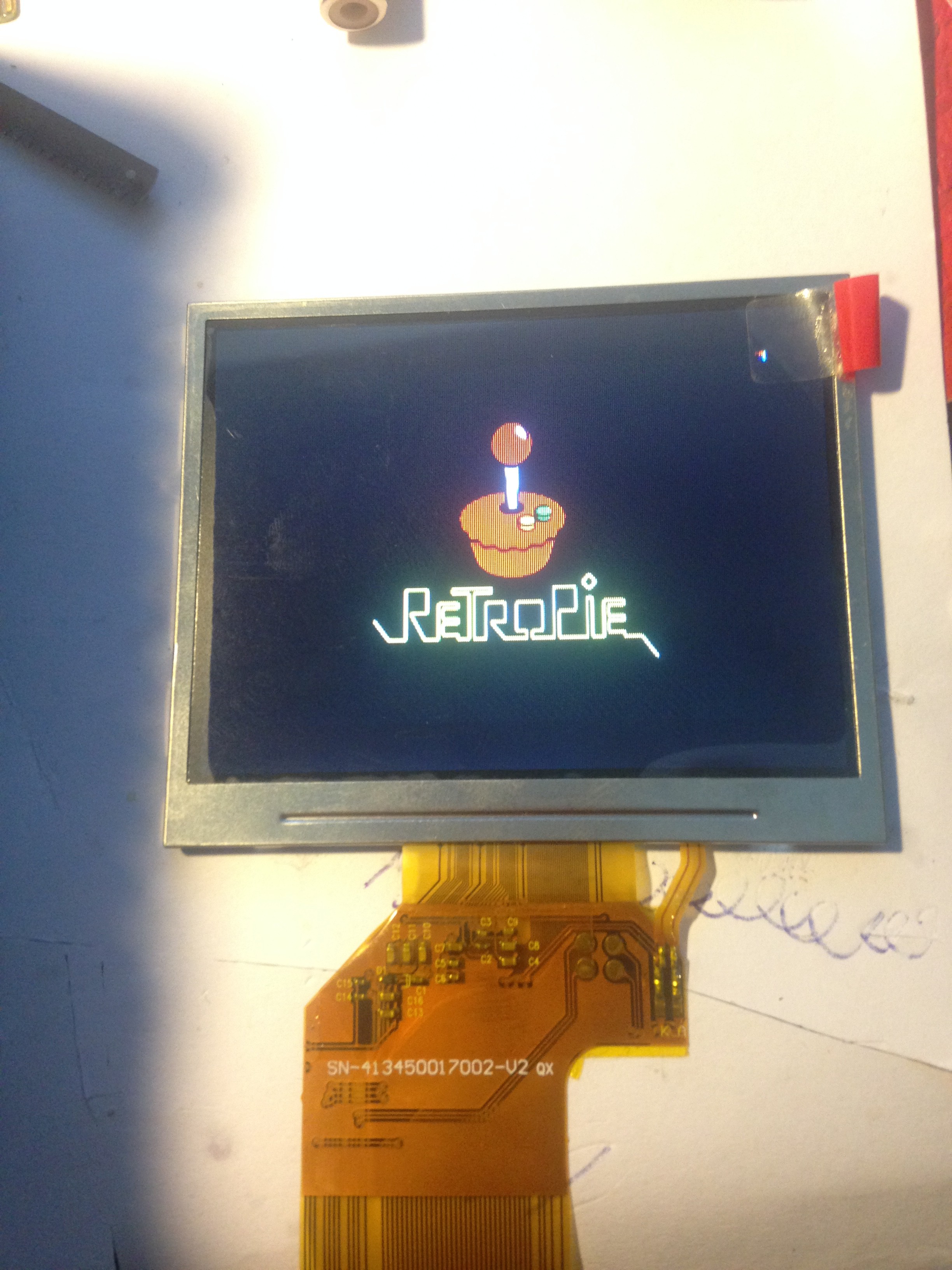
I then soldered on wires to test it out to the corresponding pins:
![]()
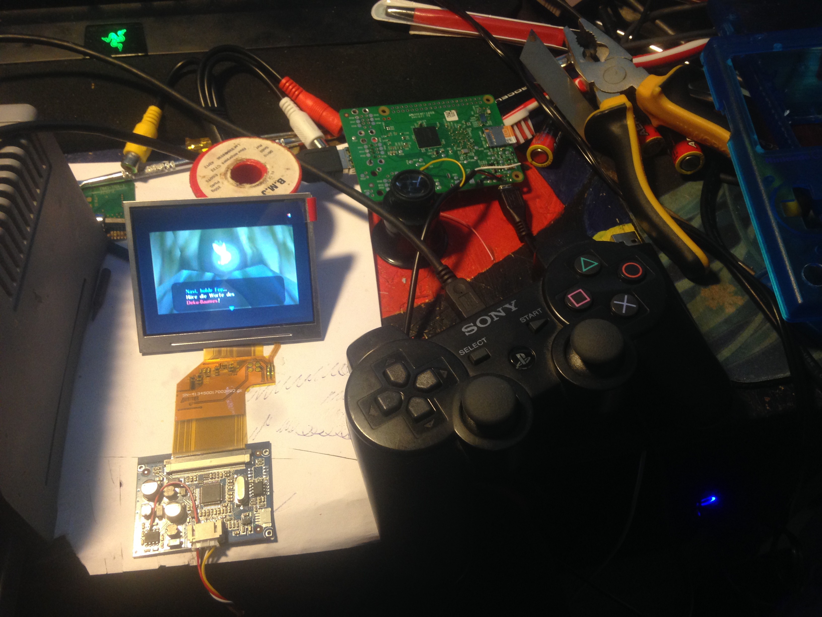
And it works!
![]()
![]()
Raspberry Pi 3 Gameboy
This is a DIY Raspberry Pi 3 gaming handheld running RetroPie to play all your classics!