FabLab München
-
New 3D printed microscope stand
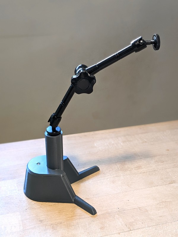
06/14/2022 at 17:17 • 0 commentsWe are currently working on a new design for our dual-camera microscope head (see previous log entry), and accompanying that we are also designing a new stand. While the previous design of the stand is nice and sturdy, it involves a bit of metal work, what might scare away some of the electronics nerds. The new one is 3D printed. It's base is hollow and can be filled with stuff to give it the necessary weight (we used lead shot, but some metal screws or nuts should work nicely too). The connection between the base and the camera head is made with a cheap "magic arm" (search for "magic arm 11 inch" in favorite online shop), allowing for easy repositioning of the cameras while still providing good rigidity.
![]()
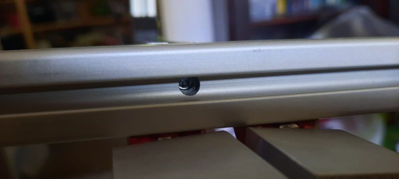
The magic arm has the typical 1/4" screws on both ends (used everywhere in photo equipment). The lower one sits in a matching brass insert to hold it firmly, while the upper one still waits for the new camera head to be finished...
-
Designing some nice Enclosure
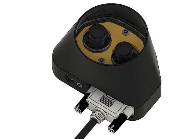
05/19/2022 at 13:06 • 0 commentsWe did some work on a nice mostly 3d printed Enclosure for the two cameras. We also diced do go for two custom PCBs: One on the Camera side and one as HAT for the Raspberry Pi. This makes it possible to replace the two flatflex cables with a more robust solution and to add buttons as user interface and LEDs to the Camera-"Head". For the cable we planning to reuse a DVI dual link cable. This has enough lines for both cameras and some extras.
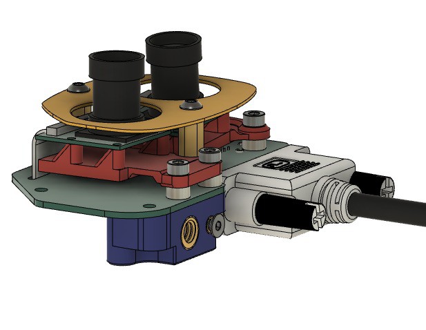
View from Bottom on the Cameras. Yellow is the place holder for the LED-PCB
![]()
Top view. The top could be any 3mm plate. I am thinking of laser cut acrylic right now. There could be also cut-outs for additional LEDs and Buttons for user interface. You can also see the mounting nut for standard camera Hardware (Magic Arm our similar).
![]()
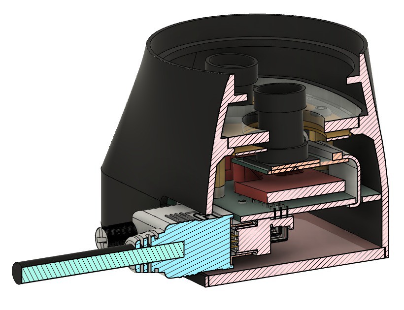
Cut to see some of the internals. Here you can also see the planned difusor (probably also laser cut acrylic) above the LED-PCB
![]()
Side view without the outer shell. It is usable like this. The outer shell is mechanically not needed it does not fall apart and the mounting nut is bolted to the PCB (green). We are also thinking of using the two stand off connecting the Main PCB (green) and LED-PCB (yellow) as electrical connection for the LEDs.
![]()
-
Choosing the right camera
07/12/2021 at 11:37 • 0 commentsTo be used for Stereo Ninja, a camera must be
- compatible with the Raspberry Pi
- have adjustable focus, or rather a interchangeable lens
- small form factor
The small form factor is important to archive a good stereoscopic effect. The distance between the cameras should correlate with the distance between the eyes. We use camera with a PCB footprint of only 25x24mm, but even when mounting these cameras closely next to each other, you get a slightly exaggerated 3D effect. This is fine (and might even help with working with the microscope) but a larger distance is not helpful and is not comfortable for the eyes.
TL;DR: Use the Waveshare RPi camera model G
Raspi Cam v1 (OV5647, 5MP)
For now, we are using Waveshare cameras with Raspi Cam v1 compatibility. They have a PCB size of 25x24mm.
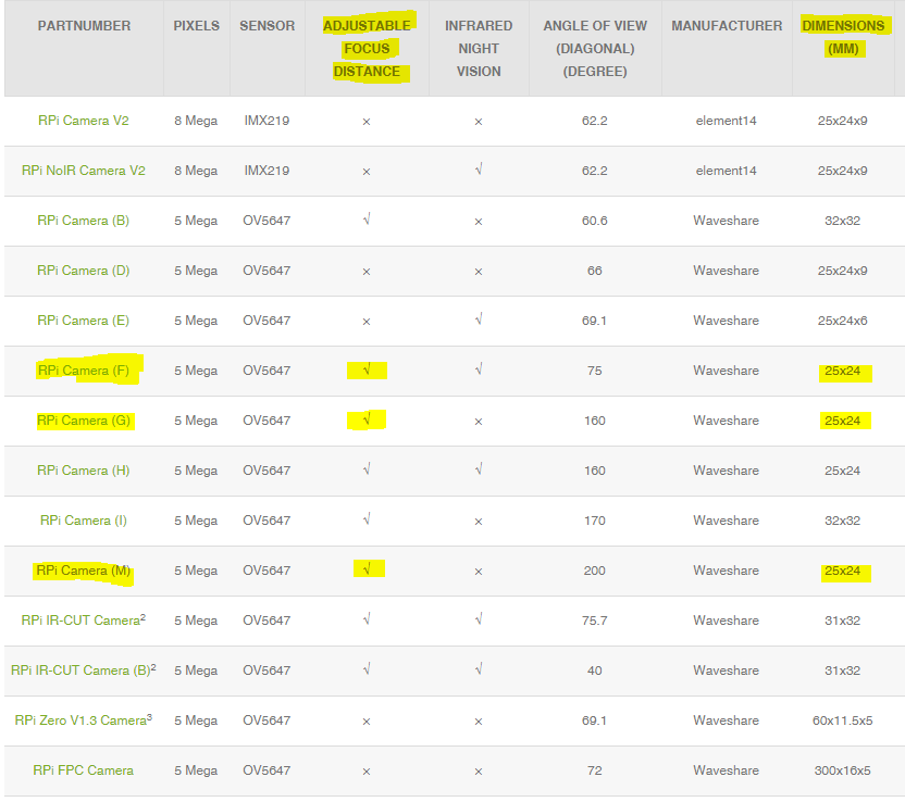
There a several variants, the following fit the specs:
![]()
Model H should be fine as well, but it comes with additional IR lights mounted on the sides of the PCB.
If using IR variants makes sense is unclear, we haven't test it.
As the lens will be exchanged anyway, you can go for the cheapest model, at the moment this is model G.
Raspi Cam v2 (IMX219, 8MP)
The official v2 cams do not have adjustable focus and the lens cannot be changed to another one, so they do not fit our requirements unfortunately.
Because the they a higher resolution they would be interesting however. One possibility would be to take a standard v2 camera PCB and swap out the camera with this one (same sensor, but interchangeable lens). Still needs testing.
Raspi HQ Cam (IMX447, 12MP)
The Raspi HQ cam certainly would be interesting to use. It has a better resolution and also a much larger sensor (6.3×4.7mm compared to 3.8×2.7mm with the v1 cam). Unfortunately it is a lot more expensive und also a lot larger. With 38x38mm the PCB footprint doesn't allow the cameras to be as close together as they would need to be. We could mount them further away and archive the same angle between the two camera, but we did not test that (yet).
-
Playing around with raspivid options
07/03/2021 at 10:13 • 0 commentsIf you look at our camera setup closely you will notice that the cameras are mounted the wrong way around. When you work sitting at the "open end" of the stand, things nearer to you will end up at the top of the screen - not what you would expect.
But this can be fixed in software: The raspivid options "-hf -vf " will flip the image horizontally and vertically, effectively rotating the image(s) by 180°. But doing so destroys the 3d effect (actually inverses it), one also needs to swap the image for the left and right eye.
Unfortunately the raspivid option "-3dswap" which looks like being exactly the option we want, does not have an effect for us. Instead, we simply swapped out the camera cables at the Raspberry Pi :-) Maybe we should have a look at the raspivid source code and see what's going on there...
Good thing: flipping the images does not add any latency (measured by our Arduino setup), so mounting the cameras the way we did it is perfectly fine.
Another thing we wanted to look into is doing digital zooming. The OV5647 sensor we use has 5M pixels, we are only displaying a FullHD image. So it should be possible to use just a central part of the sensor, archive zooming by doing so, and still don't do any interpolation. raspivid has a promising option for that: "-roi". The documentation says:
Set sensor region of interest
Allows the specification of the area of the sensor to be used as the source for the preview and capture. This is defined as x,y for the top-left corner, and a width and height, with all values in normalised coordinates (0.0 - 1.0). So, to set a ROI at halfway across and down the sensor, and a width and height of a quarter of the sensor, use:
-roi 0.5,0.5,0.25,0.25We want half of the sensor to be used located around the center of the sensor, so the full command line is:
raspivid-3d -3d sbs -dec -hf -vf -fs -t 0 -roi 0.25,0.25,0.5,0.5
This results is a nice 2x zoom, just as intended. Unfortunately, the image is now not as sharp as it was before. I don't think it is due to interpolation going on, but it is hard to tell. It is probably beyond what the optics are capable of. Testing other lenses probably is a good idea.
[Update 2021-07-16:] When I talked about digital zooming above, I didn't realize that the camera was running in mode 1 (see 'mode' option in documentation) when operating in FullHD 1920x1080 resolution. In this mode, the camera only uses the central 1920x1080 pixels, already resulting in digital zooming. Zooming further (by region of interest parameters) then of course only does interpolation. Unfortunately the camera cannot deliver 30fps at 1920x1080 using the full sensor. For a un-zoomed full sensor operation, we need to switch the camera to mode 5, resulting in a 1296x730 image that needs to be scaled up for display on a FullHD monitor. But having two modes, an "overview mode" (full FOV at 1296x730) and a "details mode" (partial FOV at 1920x1080, effectively zooming in) sounds like it would work nicely in practice. Having a non-interpolated image is especially important in the details mode, and conveniently it is the case there.
-
Latency measurements
07/02/2021 at 08:24 • 0 commentsAs we now have an Arduino based latency test setup, it was now was time to do some real tests.
![]()
This is a test made with Stereo Ninja (the vertical black line is a rolling shutter effect caused by shooting through the shutter glasses). Result: 100ms latency. This is quite long. But one clearly notices the latency when using the system, so it is not completely unexpected.
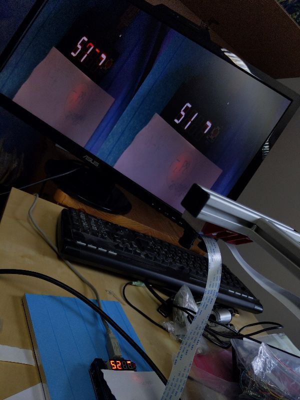
The cause for this long latency is not clear yet. In principle it should be possible to reach latency as low as 10ms. For debugging purposes we set the monitor in 2D mode, displaying the images side-by-side:
![]()
As you can see, this did not change the latency, it's still around 100ms.
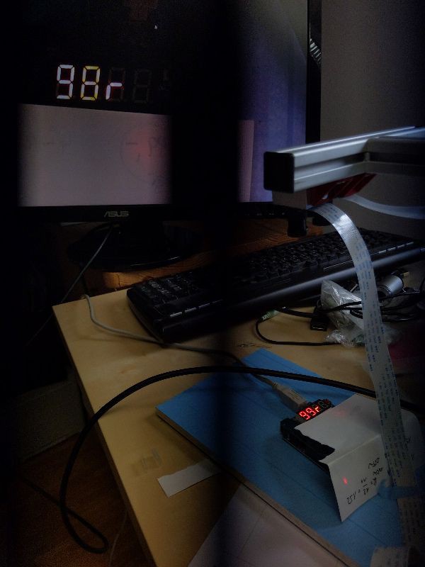
Next test: only one camera:
![]()
This clearly improves the latency, it's now around 50-60ms.
Still, it's nowhere near the 10ms which seem possible to archive. It might be the monitor, but the used model (ASUS VG248QE) is actually a gaming monitor with a response time of 1ms (at least the specs say so).
We have to do more testing. Unfortunately the used measurement method only allows for measuring latency end-to-end, so it is unclear where exactly the latency is introduced (image processing? monitor?). We probably will try to do measurements with a photo diode and check the signal against a reference signal output over a Raspi GPIO pin to determine the monitor latency. Stay tuned...
-
Measuring video latency with an Arduino
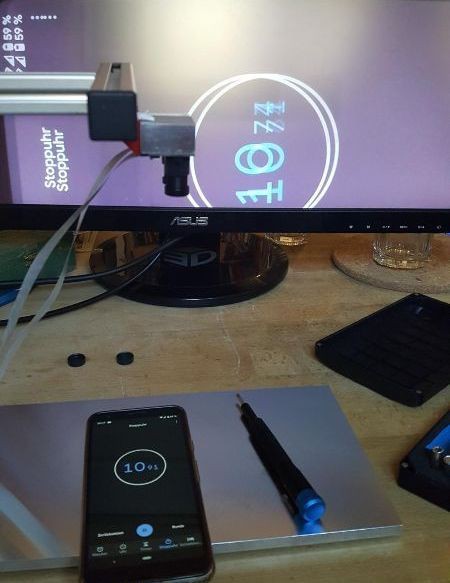
07/01/2021 at 13:33 • 0 commentsFor Stereo Ninja testing we need an easy way to measure latency. A simple way is to put a smart phone with a stopwatch app in front of the camera and then take a photo with both the smart phone and the monitor displaying the smart phone on it. Then simply substract the time stamps shown and then you have the latency:
![]()
This kind of works, but the resolution is bad. The smartphone display has a refresh rate not fast enough to update the 10ms digit correctly. There is not even a 1ms digit. And then - because of the exposure time of the cameras - several digits are visible on top of each other, making it rather hard to read the numbers. (The photo shown above is a rather readable example. Note that the photo shows both the left and right eye image superimposed as no shutter glasses were used)
So we wanted something better...
Idea:
- On a 4 digit 7-segment display a counter, counting up each millisecond (or 10 ms)
- As before, this display is put in front of the cameras, and a photo is taken also showing the monitor
- Use a good photo camera to take the photo, ideally with a exposure time < 1/1000 sec
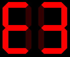
- To avoid blurring of the numbers, we do not display numbers for the least significant digit. Instead the segments of two 7-segment displays are used that form a kind of ring (using 5 segments of each display), which are lit up one after the other clockwise, like this:
![]()
These are the 10 states:
![]()
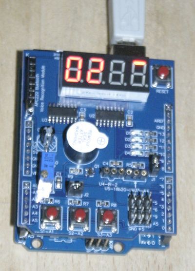
For the realization we used an Arduino Uno with a "multi functional shield" that can be cheaply bought on ebay or aliexpress.
The four 7-segment display are driven by two 74HC595. This allows using high multiplexing rates >1kHz which is a must for this project.
![]()
// Display milli seconds for latency measurements on 4-digit 7-segment display
// Written by Andreas and Simon Kahler

// Licensed under the Apache 2.0 license
// http://www.apache.org/licenses/LICENSE-2.0

/* Define shift register pins used for seven segment display */
#define LATCH_DIO 4
#define CLK_DIO 7
#define DATA_DIO 8

#define SW1 A1
#define SW2 A2

/* bits (0=LSB) for segments (1=off 0=on)
*
*        0
*       ---
*    5 |   | 1
*       ---
*    4 |   | 2
*       ---
*        3
*
*   center: 6
*   dot: 7
*
*/

/* Segment byte maps for numbers 0 to 9 */
const byte SEGMENT_MAP[] = {0xC0,0xF9,0xA4,0xB0,0x99,0x92,0x82,0xF8,0X80,0X90};

/* Segment byte maps for numbers 0 to 9 with dot */
const byte SEGMENT_MAP_WITHDOT[] = {0x40,0x79,0x24,0x30,0x19,0x12,0x02,0x78,0X00,0X10};

/* Segment byte maps for "clock ring 1 digit" */
const byte SEGMENT_MAP_RING[] = {0xFD,0xFB,0xF7,0xEF,0xDF,0xFE};
/* Segment byte maps for "clock ring 2 digit, right and left" */
const byte SEGMENT_MAP_RING2R[] = {0xFE,0xFD,0xBF,0xFB,0xF7,0xFF,0xFF,0xFF,0xFF,0xFF};
const byte SEGMENT_MAP_RING2L[] = {0xFF,0xFF,0xFF,0xFF,0xFF,0xF7,0xEF,0xBF,0xDF,0xFE};

const byte SEGMENT_EQ = 0xB7; // =
const byte SEGMENT_D = 0xA1; // d

/* Byte maps to select digit 1 to 4 */
const byte SEGMENT_SELECT[] = {0x01,0x02,0x04,0X08};

byte mode = 1;
byte multiplier = 10;

void setup ()
{
  /* Set DIO pins to outputs */
  pinMode(LATCH_DIO,OUTPUT);
  pinMode(CLK_DIO,OUTPUT);
  pinMode(DATA_DIO,OUTPUT);

  pinMode(SW1, INPUT_PULLUP);
  pinMode(SW2, INPUT_PULLUP);
}

/* Main program */
void loop()
{
  if (digitalRead(SW1)==LOW)
  {
    sw1Pressed();
  }
  if (digitalRead(SW2)==LOW)
  {
    sw2Pressed();
  }
  long i = millis() / multiplier;
  /* Update the display with the current counter value */
  switch (mode)
  {
    case 0: // 4 digits
      WriteNumberToSegment(0 , SEGMENT_MAP[(i/1000)%10]);
      WriteNumberToSegment(1 , SEGMENT_MAP[(i/100)%10]);
      WriteNumberToSegment(2 , SEGMENT_MAP[(i/10)%10]);
      WriteNumberToSegment(3 , SEGMENT_MAP[i%10]);
      break;
    case 1: // 1 ring + 2 digits
      WriteNumberToSegment(0 , SEGMENT_MAP[(i/100)%10]);
      WriteNumberToSegment(1 , SEGMENT_MAP[(i/10)%10]);
      WriteNumberToSegment(2 , SEGMENT_MAP_RING2L[i%10]);
      WriteNumberToSegment(3 , SEGMENT_MAP_RING2R[i%10]);
      break;
    case 2: // 2 rings
      WriteNumberToSegment(0 , SEGMENT_MAP_RING2L[(i/10)%10]);
      WriteNumberToSegment(1 , SEGMENT_MAP_RING2R[(i/10)%10]);
      WriteNumberToSegment(2 , SEGMENT_MAP_RING2L[i%10]);
      WriteNumberToSegment(3 , SEGMENT_MAP_RING2R[i%10]);
      break;
  }
}

void sw1Pressed()
{
  switch(multiplier)
  {
    case 1: multiplier = 3; break;
    case 3: multiplier = 10; break;
    case 10: multiplier = 30; break;
    default: multiplier = 1;
  }
  for (int i=0; i<1000; ++i)
  {
      WriteNumberToSegment(0 , SEGMENT_MAP[1]);
      WriteNumberToSegment(1 , SEGMENT_EQ);
      WriteNumberToSegment(2 , SEGMENT_MAP[(multiplier/10)%10]);
      WriteNumberToSegment(3 , SEGMENT_MAP[multiplier%10]);
  }
}

void sw2Pressed()
{
  switch(mode)
  {
    case 0: mode = 1; break;
    case 1: mode = 2; break;
    default: mode = 0;
  }
  for (int i=0; i<1200; ++i)
  {
      WriteNumberToSegment(0 , SEGMENT_D);
      WriteNumberToSegment(1 , SEGMENT_EQ);
      WriteNumberToSegment(3 , SEGMENT_MAP[mode]);
  }
}

/* Write a decimal number between 0 and 9 to one of the 4 digits of the display */
inline void WriteNumberToSegment(byte Segment, byte Value)
{
  digitalWrite(LATCH_DIO,LOW);
  shiftOut(DATA_DIO, CLK_DIO, MSBFIRST, Value);
  shiftOut(DATA_DIO, CLK_DIO, MSBFIRST, SEGMENT_SELECT[Segment] );
  digitalWrite(LATCH_DIO,HIGH);
}
Results
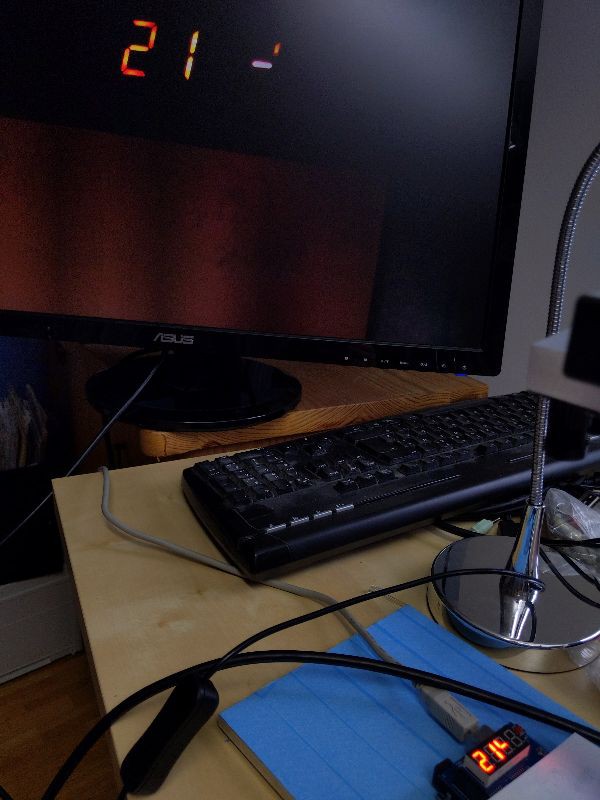
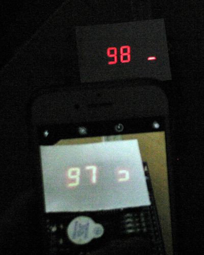
Here is a test with a iPhone8 in photo mode ("measurement" photo taken with a DLSR):
![]()
- A piece of paper was put on top of the 7-segment display, this made it easier to take a photo (display was overexposed otherwise)
- The Arduino code was run in 1/100sec mode
- 3 segments are visible on the iPhone display → exposure time is around 30ms
- The timestamp of the exposure is 9.73 to 9.75
- The timestamp of the measurement is 9.85
- Latency here is around 100ms (9.85 secs - 9.75 secs)
With a relatively long exposure time of 30ms on the iPhone and a latency of 100ms a measurement in 1/1000sec mode does not make sense here. But the concept seems to work nicely!
Next step: try it out with the Stereo Ninja!
-
Stereo Ninja is a 2021 Hackaday Prize Finalist!
06/28/2021 at 16:34 • 0 comments![]()
-
How to light up your StereoNinja stereo microscope
06/17/2021 at 23:26 • 0 commentsf you've followed StereoNinja's previous logs, you'have seen that we have used a lighting setup based on a single IKEA Jansjö light.
![]()
While this might seem like a primitive and cheap solution, consider its benefits:
- Anyone can acquire IKEA lamps easily, worldwide. No more need to worry about the much feared "This item is not available in your country yet" warning
- It's easy to setup for every individual situtation, so when you've got a special situation with some element that requires you to move the lamp, it's trivially easy to do.
- It's trivial to experiment around with the placement
- It's inexpensive - much more so than having a customized lighting PB
- It's bright. 3W of LED output for 15€.
- If it breaks, it's easy to replace
- It's just a single LED, so it only creates one shadow
- You can easily use multiple ones if you need more light
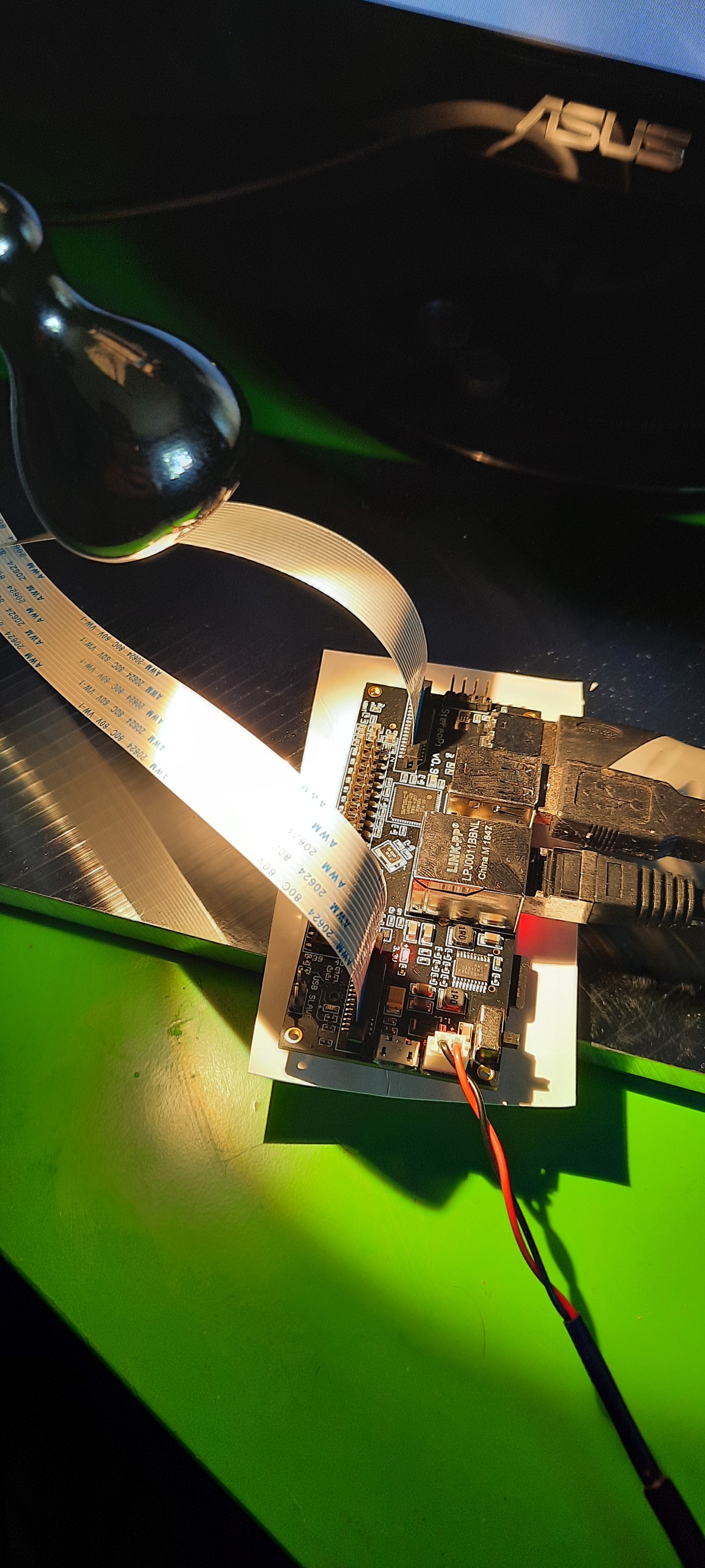
Look at how nicely this PCB is lit by the Jansjö light:
![]()
You can see the slight shadows, which add a little bit to the 3D effect. In general, our tips on how to light your board for StereoPi are:
- Place your lights as close as possible to your PCB, but keep it so far away that your entire work area is lit evenly and that the camera doesn't obstruct the view.
- Angle is more important than distance. In order to prevent large shadows, try to light mostly from above, not so much from the side
- If using multiple lights, try to keep them at approximately the same angle from the vertical in order to prevent one light casting short shadows and the other light casting long shadows
- Keep in mind that if you're using tweezers or a soldering iron, these will cast a shadow themselves, depending on where you are holding them. So you might need to adjust the position and angle of your lights so whatever you're soldering will still be lit properly
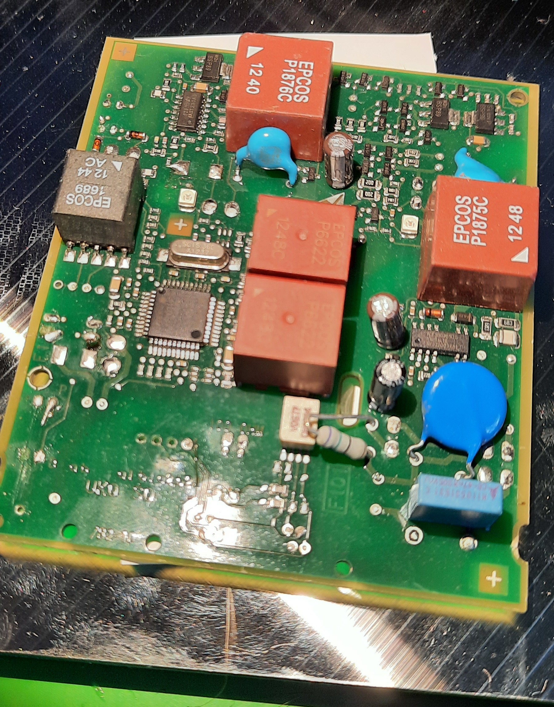
This is how too long shadows look on a PCB: They will typically not add to the 3D effect too much, they will just hide things from your view.
![]()
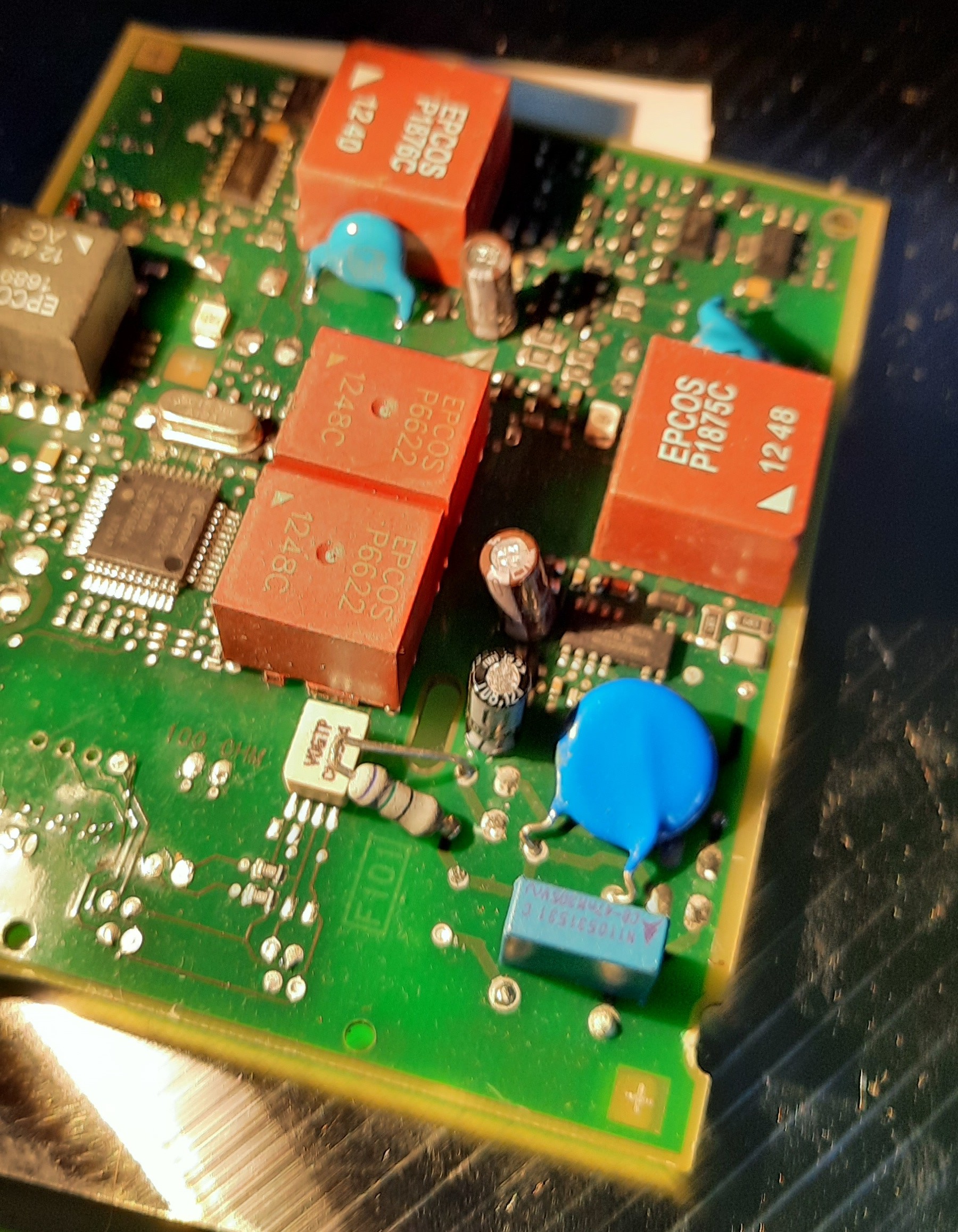
Or look at this image of our StereoPi where the middle part is lit just fine, but the shadows from the camera cable obstruct a lot of components behind them.
![]()
As a final note: We are working on an easy-to-do modification of the Jansjö lights so you'll be able to mount them directly on our StereoPi stand - in other words: In the future you won't need any more desk space to mount your lights :-)
-
Stereo Ninja at Maker Faire Hannover (Digital Edition) Tomorrow!
06/17/2021 at 11:43 • 0 commentsWe'll be presenting Stereo Ninja at the (virtual) Maker Faire Hannover tomorrow (18 Jun 2021). Visit us at the FabLab München booth!
![]()
-
Details on the camera stand
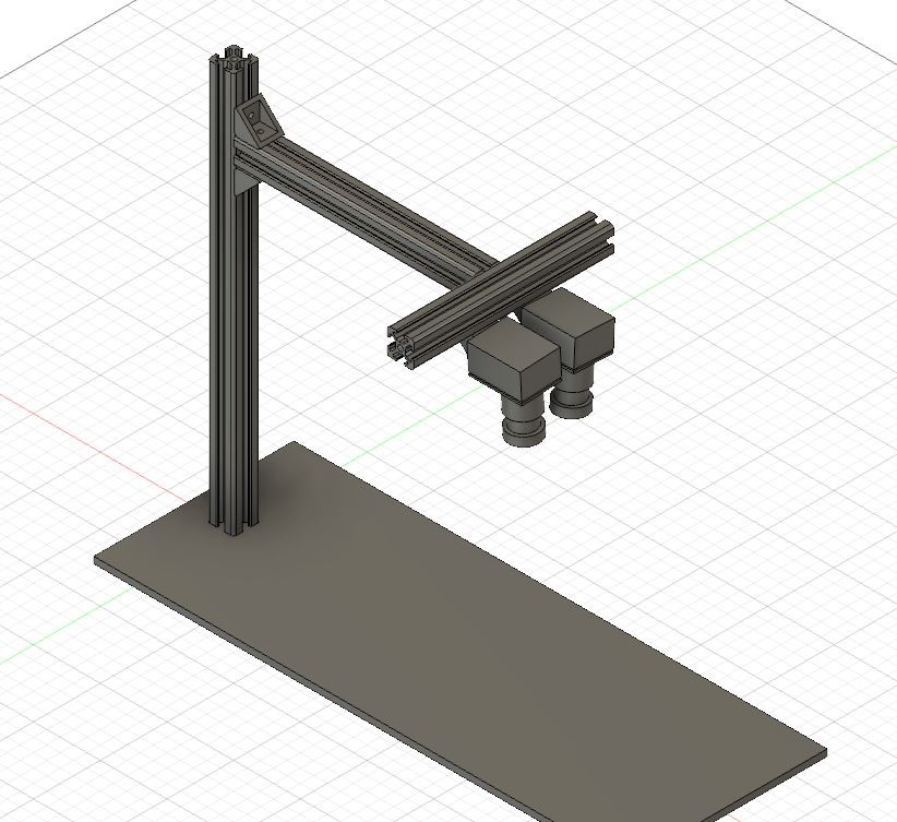
06/14/2021 at 12:50 • 0 commentsWe've modelled the camera stand in CAD (see files section for STEP file), so it is easier to build for you.
![]()
We will add build instructions as well. [Update: Build instructions are available in the Instructions Section now]
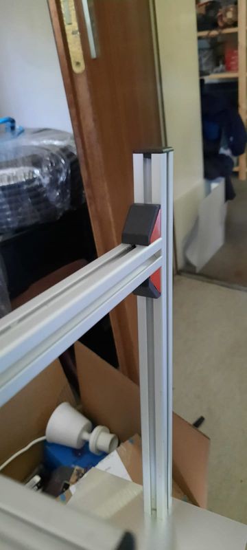
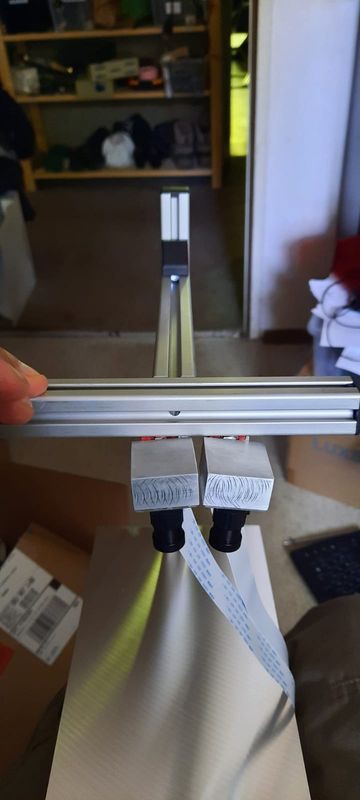
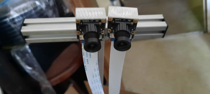
Here are some detail shots for the meantime:
![]()
![]()
![]()
![]()
![]()
![]()
![]()
Stereo Ninja
A DIY digital stereo-microscope. Low cost. Open source software and hardware. For electronics inspection, soldering work and more.