Victor Barahona
-
It works !!
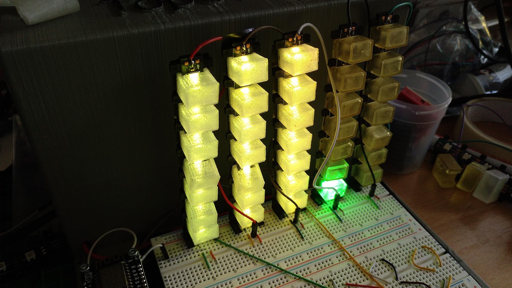
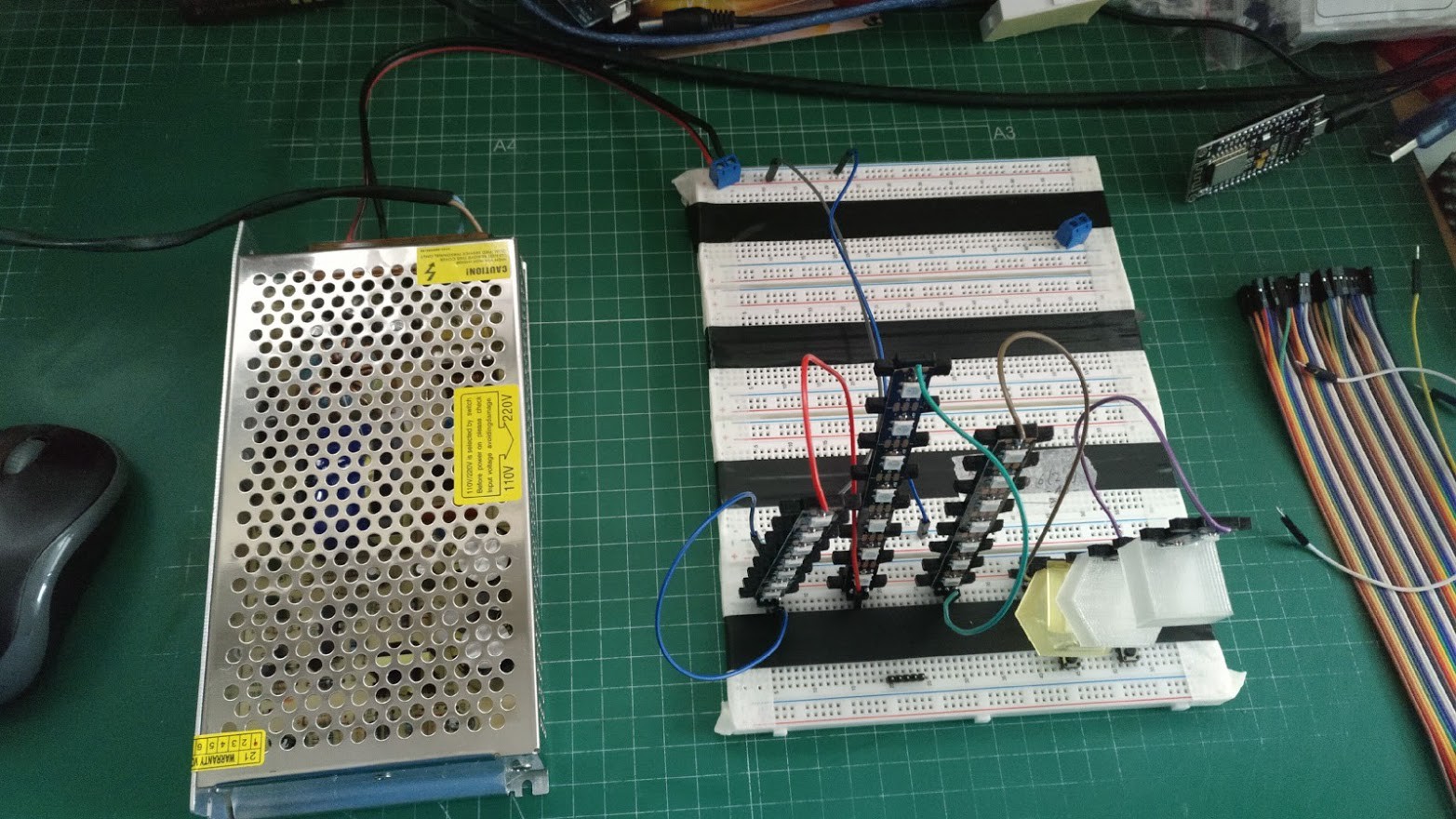
06/13/2021 at 21:55 • 0 commentsThis week has been hard but I finally get some results. Here I have the first columns working, but some problems too. the fourth column don't works as you can see:
![]()
It's my first experience with addresable LEDS and some problems are strange for me. I have ichecked a lot ot things and finally all my problems come from bad solderings. It seems that soldering and wiring are fine, but the data channel is broken in some place. This problem delayed me and unfortunatelly I can't finish the whole array now. I hope in one week more it will be finished.
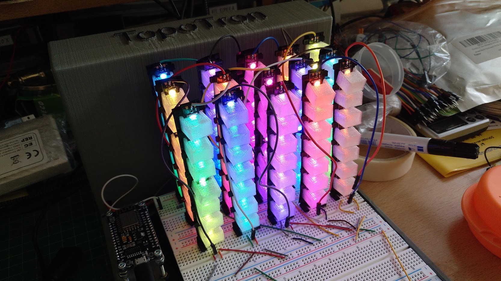
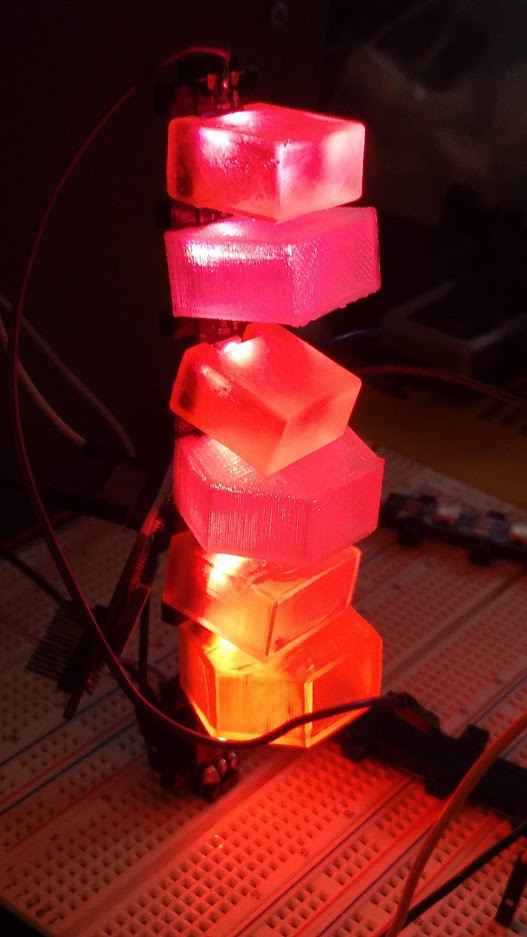
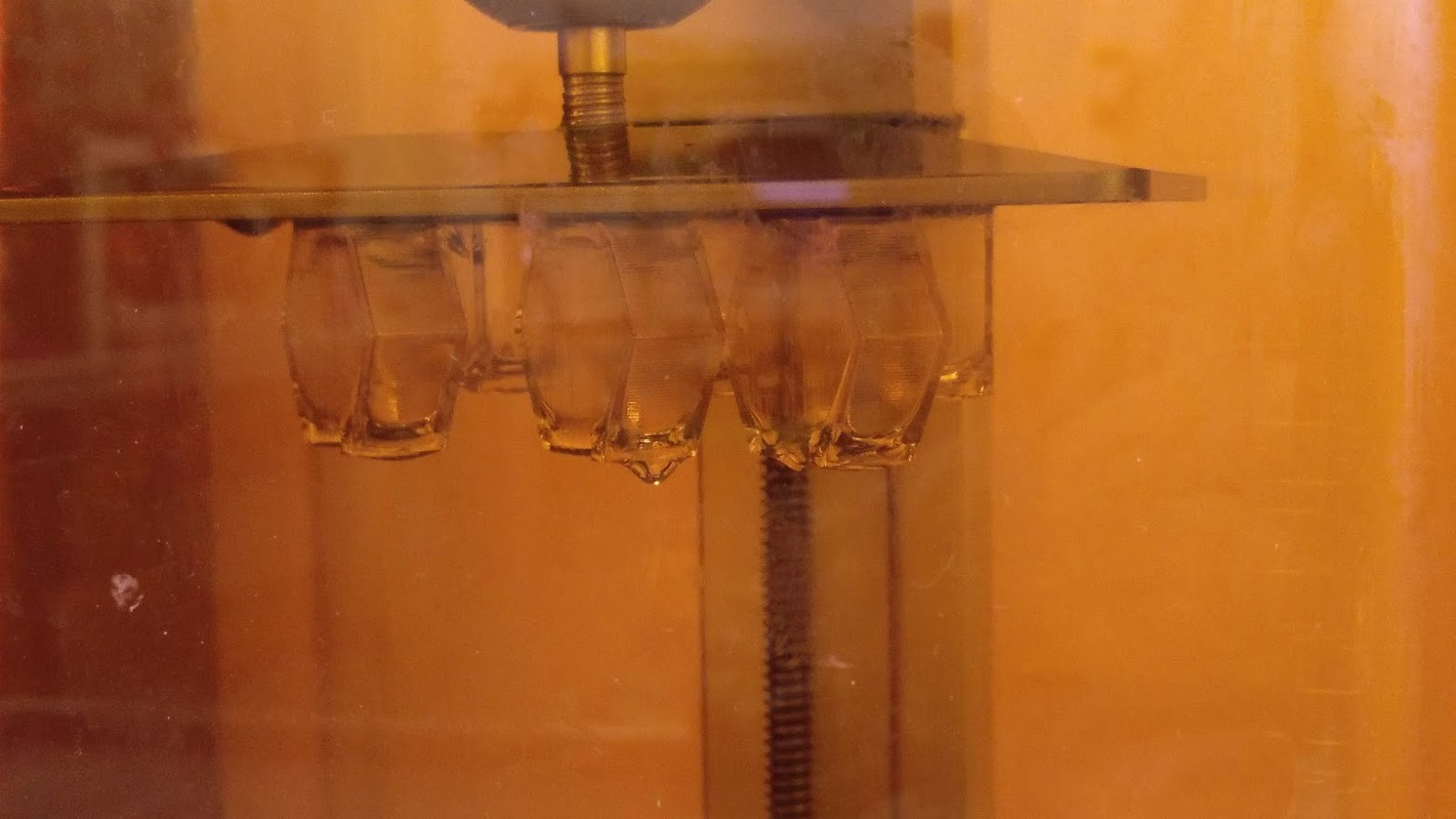
But I have at the moment 7x5x3 voxels, 105 . It's enough to see some results:
![]()
Also I have edited a short video pitch to include in this project. Enjoy !!
As I have said , if this project is finalist I will make the "big" version of TopoTron.
Anyway , I'm happy because I developed this project very fast. The idea was in my mind since a lot of years ago, and finally comes to reality in two weeks.
-
Mass production :)
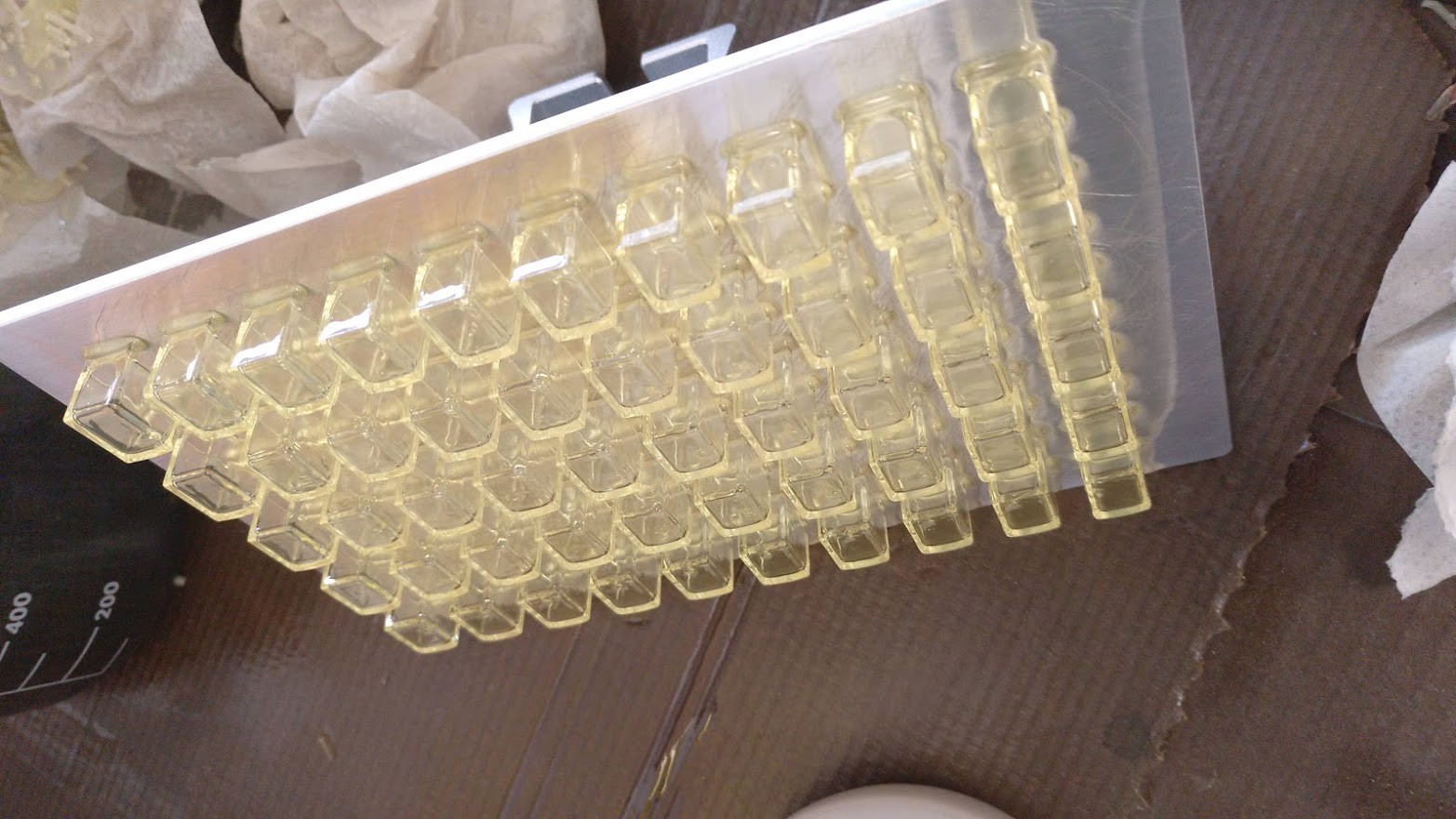
06/12/2021 at 19:07 • 0 commentsIt's time to produce a big amount of diffusers , one for each LED. This version of Topotron has 7x5x8 so it needs 280 diffusers.
I'm printing in transparent PLA and uncoloured resin. So many diffusers as I can to try to be in time to show it up and running as soon as possible.
In this picture we see a resin batch before to wash in alcohol an UV treatment:
![]()
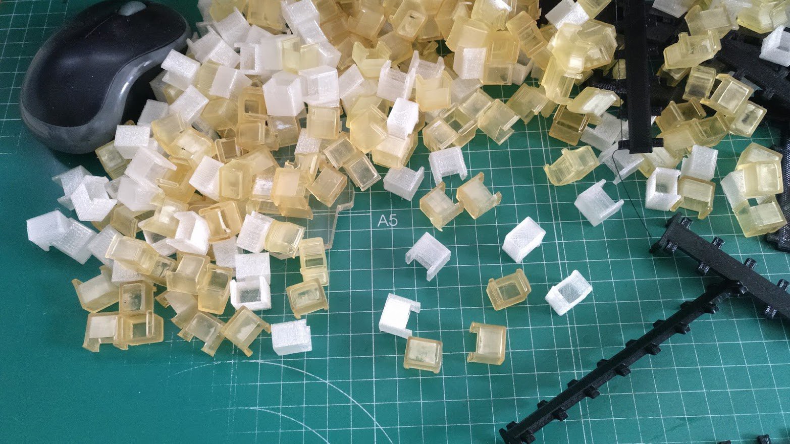
And here we see a bunch of diffusers, a mountain of them.
![]()
In this picture we see the process to create every module with 7 LEDs, from bottom to top.
![]()
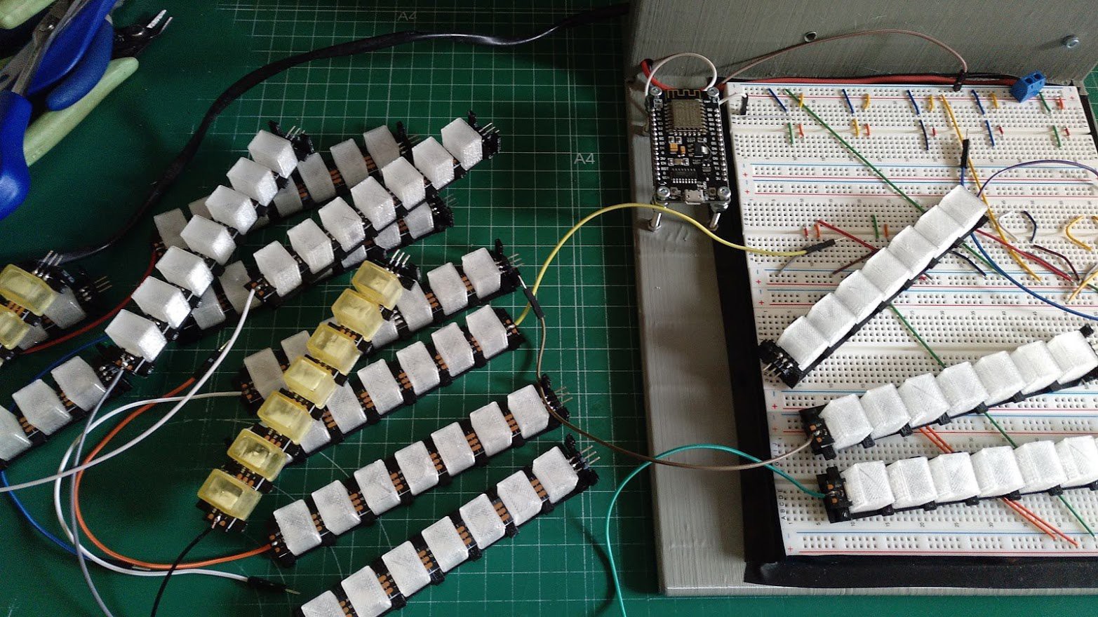
And finally the assembly of modules in breadboards. I'm having problems with testing, every module works fine but don't work correctly when I connect them in cascade. I'm troubleshhoting that problems. More info soon.
![]()
-
Frame and minor details
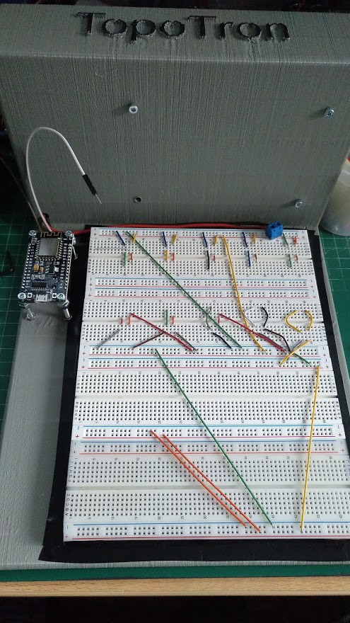
06/10/2021 at 21:52 • 0 commentsI have created a 3d printed piece to contain the power supply and Topotron. This piece has 30x20x15cm and is made in one piece. Here it is:
![]()
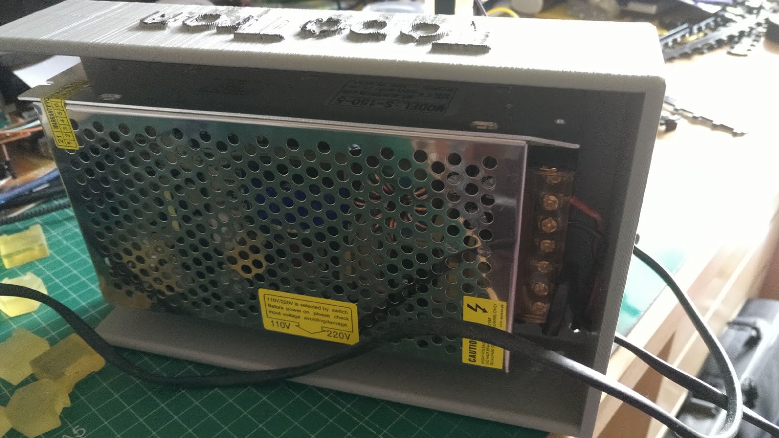
In the back is the space to hold the power supply. With 2 holes for power AC input an 5VDC output.
![]()
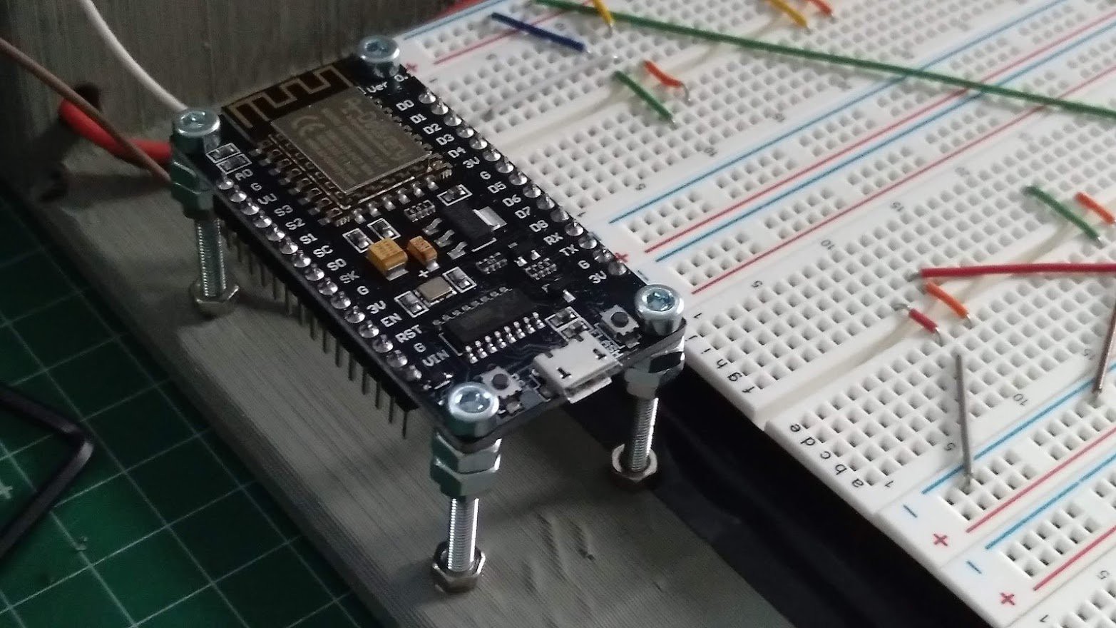
Look my "solution" to attach the ESP8266. As you know the V3 version don't fit correctly in a breadboard. So I put 4 M3x25mm screws and some nuts. The bottom is glued to the frame. I'm sorry but I'm prototyping and this solution works. I'll fix it in the future, I promise.
![]()
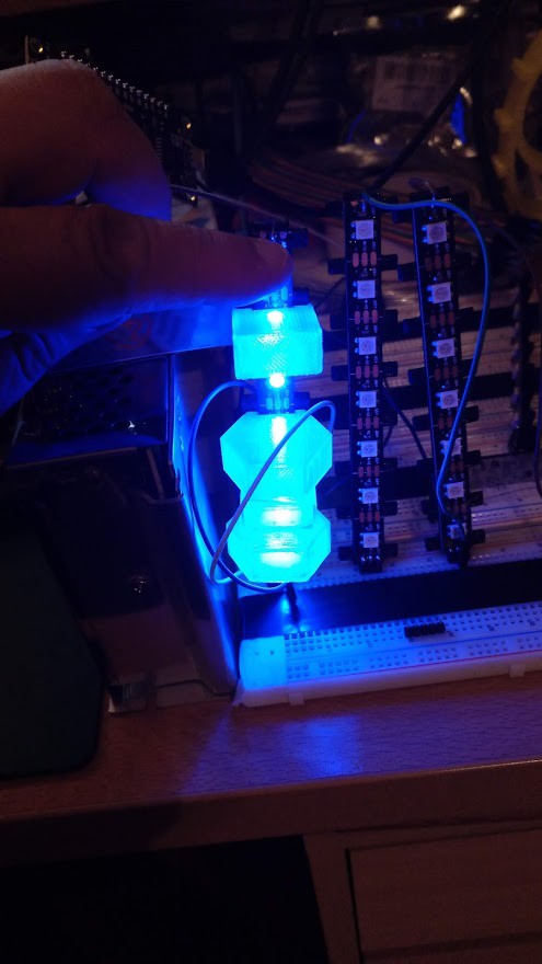
Testing with 1 module and diferent diffusors, looks nice. I'm preparing more modules to start with a minor version of the final matrix and make some effects. Stay tuned!
![]()
-
First testing with vertical LED tiles and ESP8266
06/09/2021 at 12:15 • 0 commentsA new update to see the pieces to create each z axis.
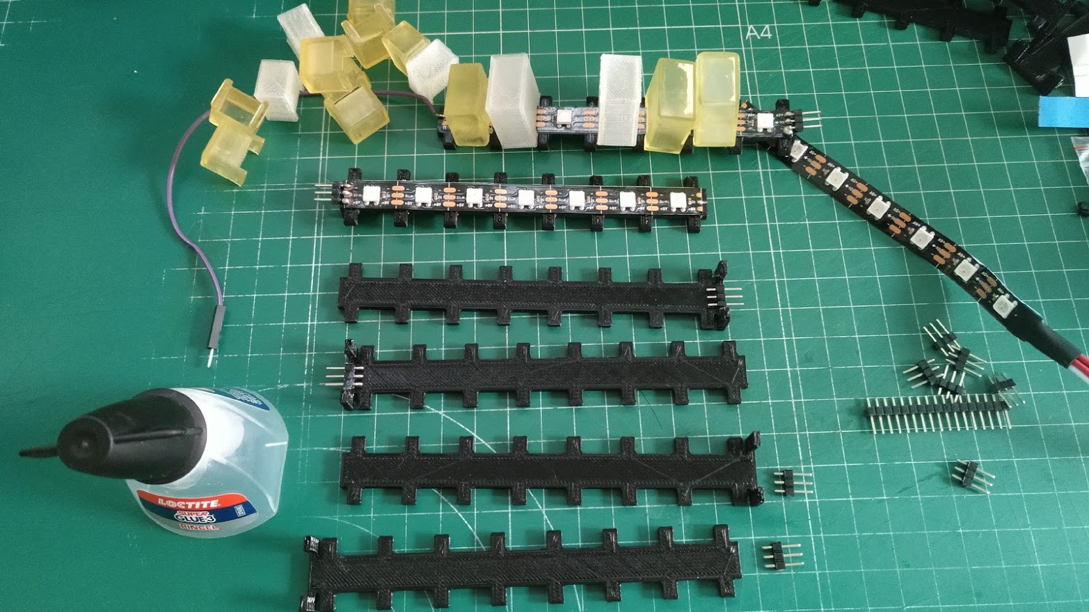
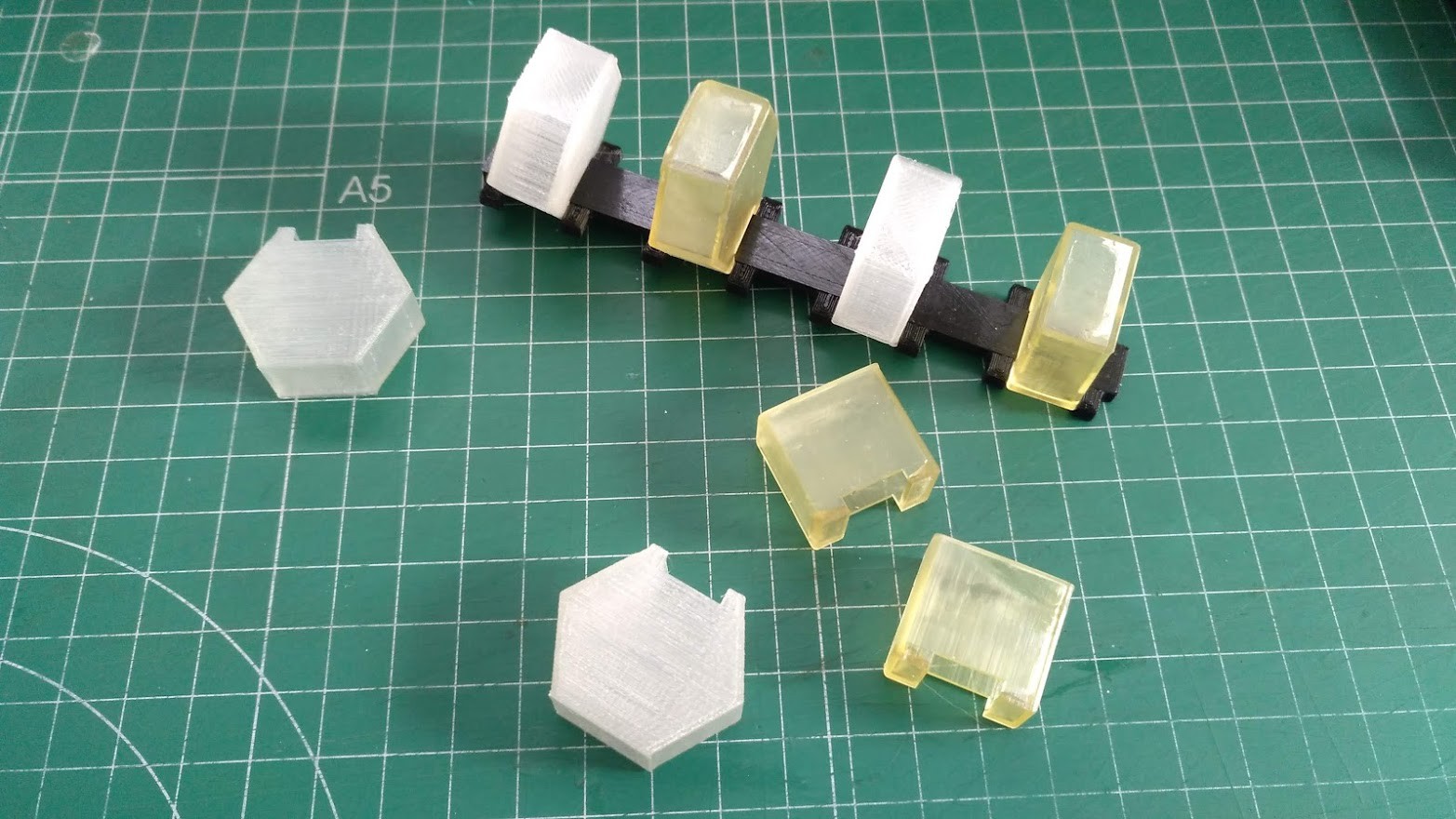
I use LED strips with 7 LEDs. I need a holder and some diffusers. I have created several versions to test them and see the best result. In this picture we see cuad and hexa tiles, in transparent PLA and resin. also we see the holder for 7 LEDs.
![]()
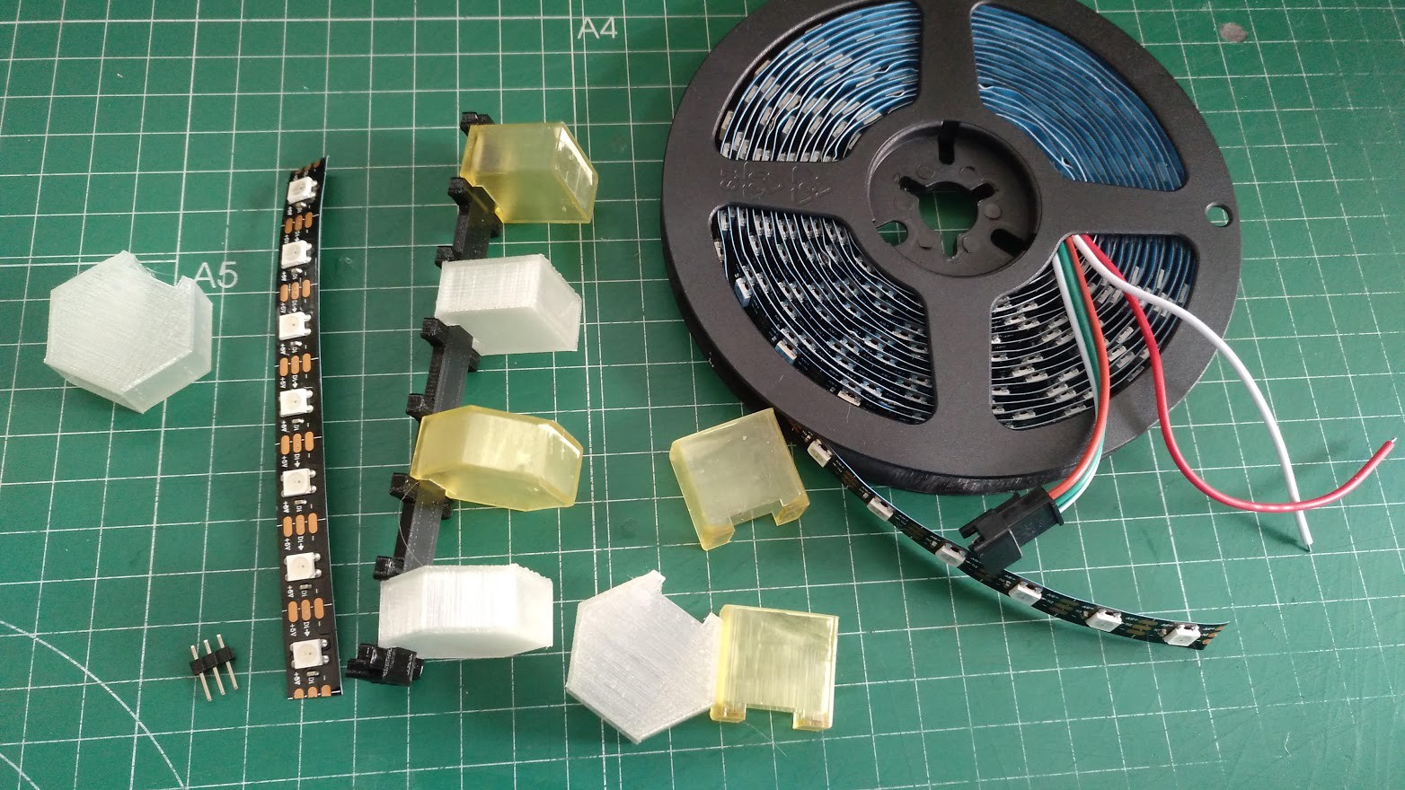
The components before soldering:
![]()
I create several modules and put them in the breadboard. This is a first test with a few pieces to see the ESP8266 is working correctly.
![]()
And finally the first results. I continue testing with other designs and soon the complete matrix will be made.
![]()
-
Defining array XY and printing some pieces
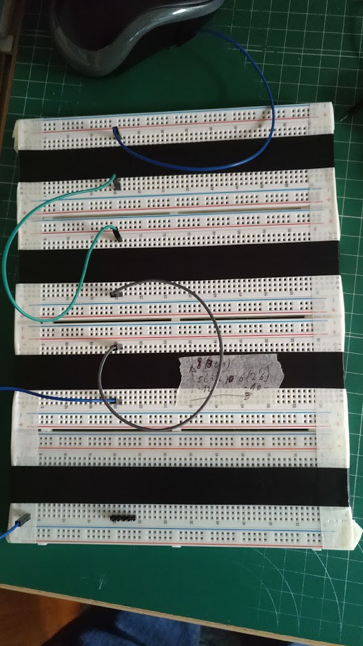
06/07/2021 at 19:25 • 0 commentsIn this phase (first prototype) the project is developed with 4 breadboard that I have join to have a good area to work.
I play with wiring a bit to define the XY array. I want at least 3cm between every point. That means 8 rows and 5 or 6 columns. It's enough for this prototype.
![]()
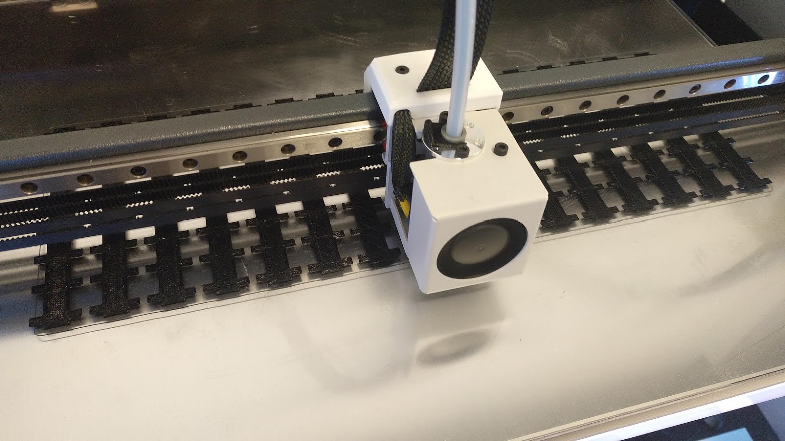
In Z axis I need a suppor for LED strips and diffusers. I think that seven LEDs are a good quantity for each support. I have designed a piece and print a bunch of them to testing.
![]()
Also I have designed several diffusers to print with transparent PLA and transparent resin. With square and hex shape, fully solid and hollow. I'm testing all of them to see the best result.
![]()
More info soon, work in progress