Close
0%
0%

Tardygrade

3D printed quadruped with a tiny BOM

Similar projects worth following
Tardygrade is a fun little robot that's easy to build using commonly available components.

It employs an unconventional mechanism which requires only two motors, yet allows for full mobility. It walks forward and in reverse, turns left and right, and pivots 360° on the spot. It also does well on uneven terrain.

Tardygrade is designed specifically for FDL manufacture:
• The robot body is entirely 3D printed. No screws needed except for mounting the servos.
• All parts prints without support.

The Tardygrade controller PCB connects to an ESP32 dev board:
• You can use your phone to remote control Tardygrade through a web based UI.
• The PCB can be fitted with laser distance sensors, which lets the robot explore autonomously.

Everything required for building it yourself will be open sourced. See details further below.


Tardygrade is my attempt to leverage some tried and true mechanical linkages into a simple yet capable robot walker. Rather than trying to emulate gait and leg articulation from biology, I started out with a mostly clean slate.

My only two guidelines were: 

  • Minimize the number of servo motors. 
  • If possible, use only 3D printed parts.

The design philosophy has been strictly utilitarian—function over form in every case. It was only after the fact I noticed that the thing ended up being rather cute, and looking a little bit like a tardigrade.
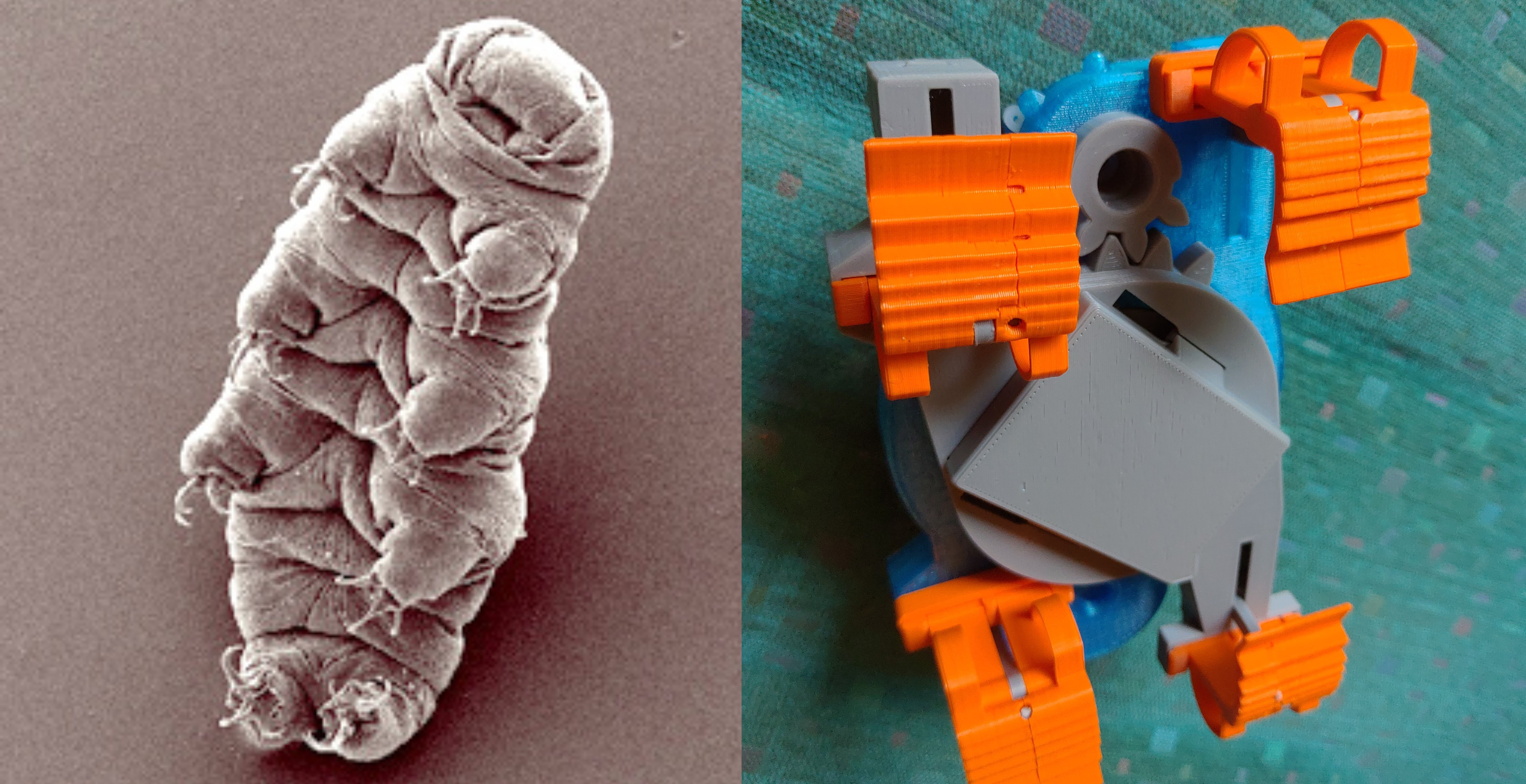
Two peas in a pod. (Left image is creative commons, courtesy of Bob Goldstein and Vicky Madden, UNC Chapel Hill)

I've put a great deal of effort into making the robot body entirely 3D printable. Instead of screws or glue, Tardygrade relies on a combination ridges, snap fits and printer filament to keep itself together.  

All in all there are 37 printed parts. Assembly should take about half an hour.

The 3D model is being developed using Free-CAD and OpenSCAD.

Controller

Automation control is based around the ESP32 µC. I'm designing a 5x5 cm printed PCB that acts as a shield for an ESP32 dev-board. The PCB has two pairs of pin headers, for compatibility with both the "Adafruit HUZZAH32 Feather" and the "Tinypico" form factors.

The shield has three main functions:

  • Allows the ESP32 to perform motion control via four hall sensors, which detects the position of a magnet mounted inside the main gear.
  • Voltage regulation for the servo motors.
  • Hardware interface to laser distance sensors.

I'm also planning to add a downward-facing rgb led, to illuminate the robot body from within. There's no practical utility in doing that. I just think it would look cool.

I'm designing the PCB using KiCad EDA. Prototype boards were made by Aisler.
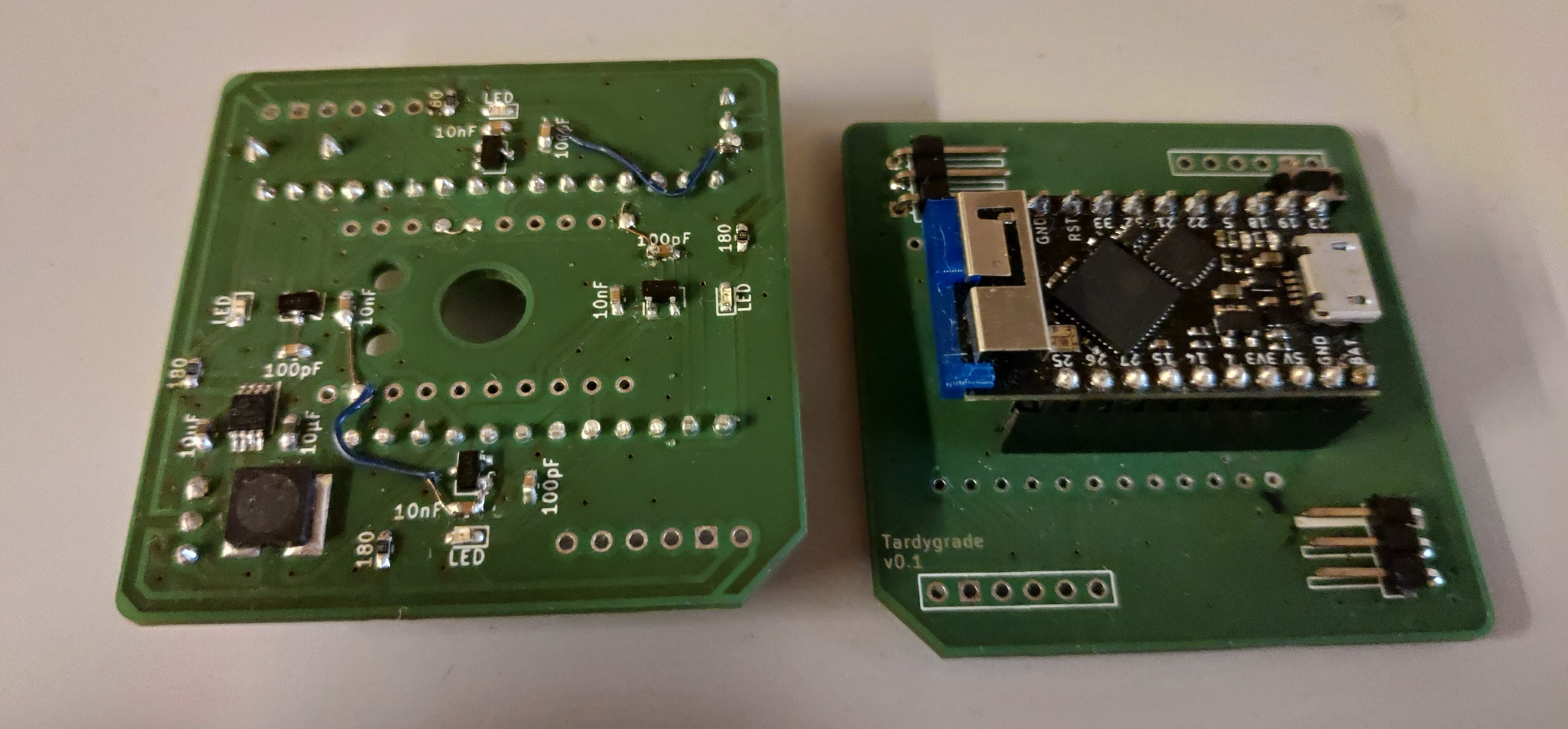
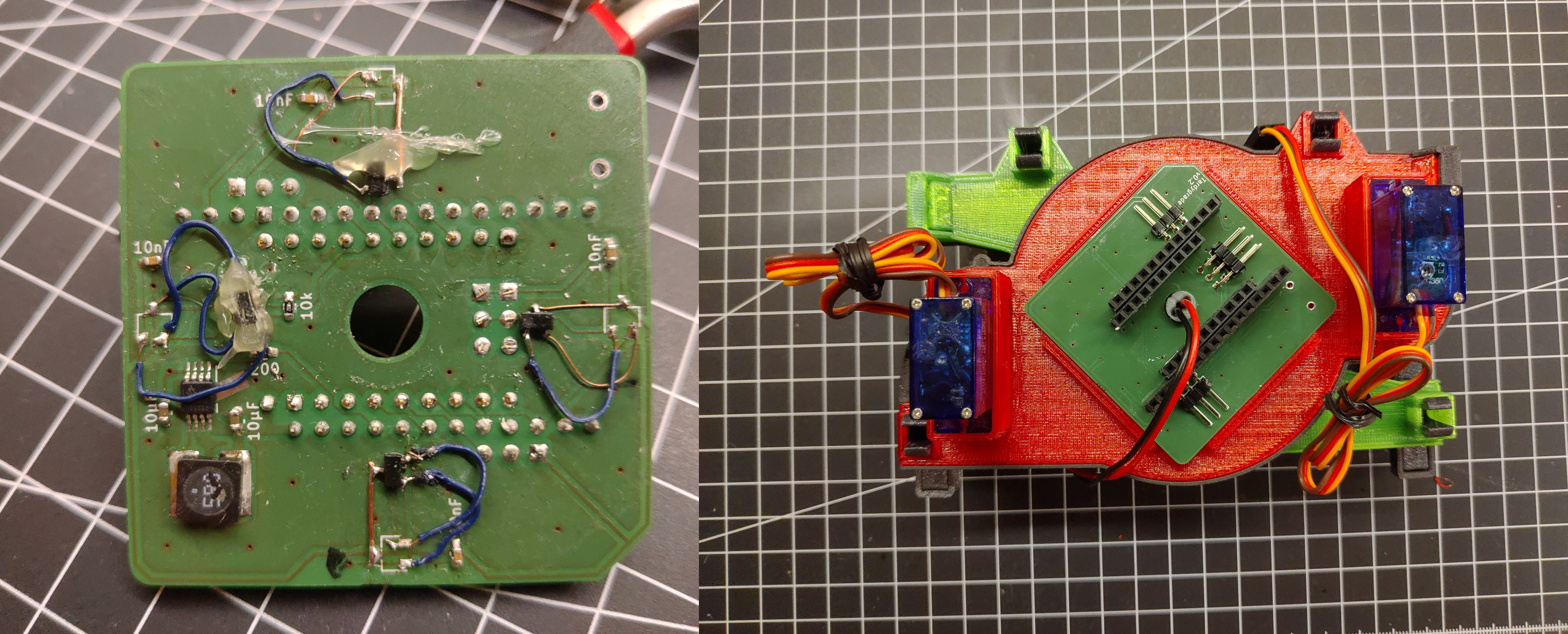
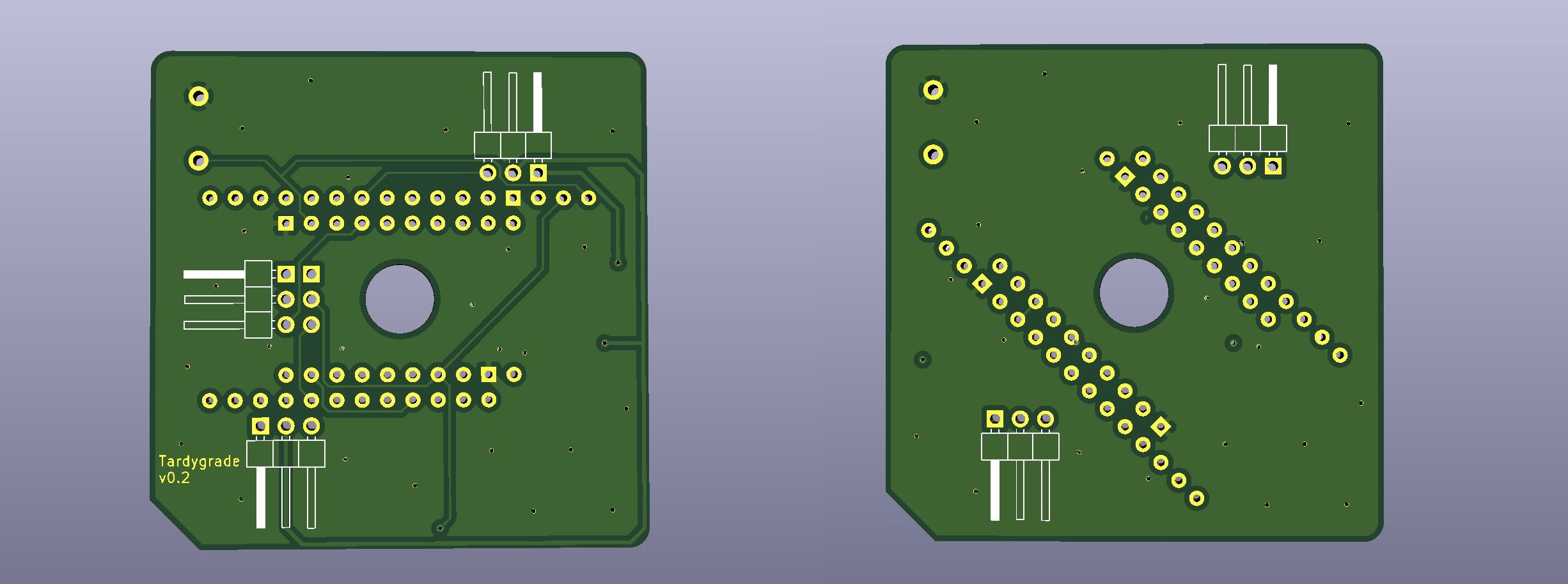
My first attempt at a printed PCB, complete with botch wires. The shield on the right is rocking the excellent Tinypico dev-board.

Software

The automation software is being written in MicroPython. 

For web server on the ESP32 I use Microdot. User interface is written mainly in JavaScript, for remote control via a phone web browser. In addition, the web server provides HTTP endpoints for accessing all automation functions. 

I will probably add some simple AI boilerplate that lets a Tardygrade fitted with distance sensors walk about autonomously. The boilerplate code can then be extended by users who want to experiment with their own AI code.

At some point I might start working on an Arduino port as well.

"Steering wheel" prototype for the web UI. Controls for direction and speed.

Source files

All project source files are available on GitHub under the creative commons licence. 

Bill of materials (pdf)https://github.com/dejanristic78/Tardygrade-BOM
3D CAD model (FreeCad)https://github.com/dejanristic78/Tardygrade-3d-model
3D printing files (stl)https://github.com/dejanristic78/Tardygrade_stl_files
Controller PCB (KiCad)https://github.com/dejanristic78/Tardygrade-pcb
Prototyping shield PCB (KiCad)https://github.com/dejanristic78/Tardygrade-shield-pcb.git
Source code (Micropython, Javascript)https://github.com/dejanristic78/Tardygrade-code.git
Build instructions

Tardygrade is still under development, which means all features are not full-fledged yet. If you would like to build the robot right now, I recommend that you join the Tardygrade Discord server. I will offer support, and welcome all feedback.
PM me for details.
1_exploded_ model_above.png

Portable Network Graphics (PNG) - 220.10 kB - 07/05/2021 at 16:25

Preview

2_exploded_model_below.png

Portable Network Graphics (PNG) - 248.86 kB - 07/05/2021 at 16:25

Preview

3_exploded_model_side_a.png

Portable Network Graphics (PNG) - 42.75 kB - 07/05/2021 at 16:25

Preview

4_exploded_model_side_b.png

Portable Network Graphics (PNG) - 39.14 kB - 07/05/2021 at 16:28

Preview

5_exploded_model_top.png

Portable Network Graphics (PNG) - 58.35 kB - 07/05/2021 at 16:28

Preview

View all 7 files

  • Assembly manual

    Dejan Ristic06/21/2023 at 17:53 0 comments

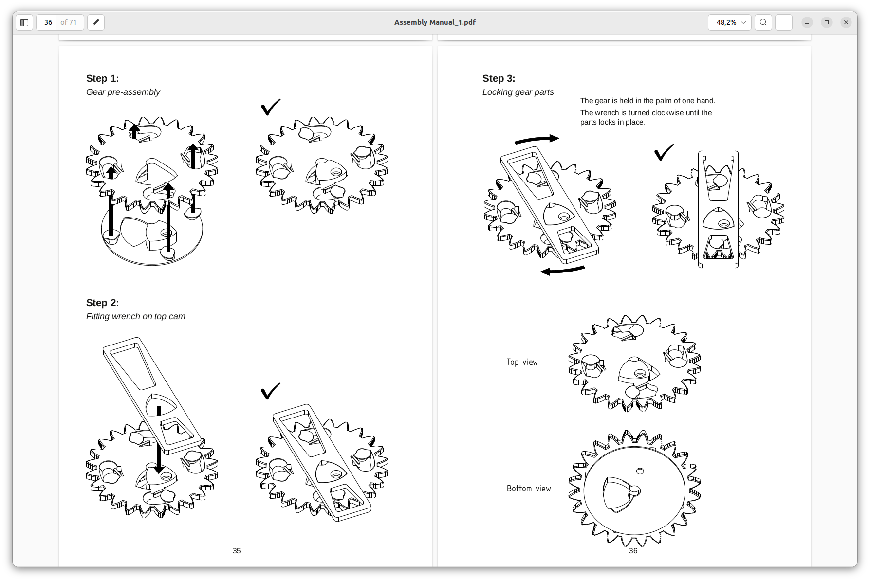
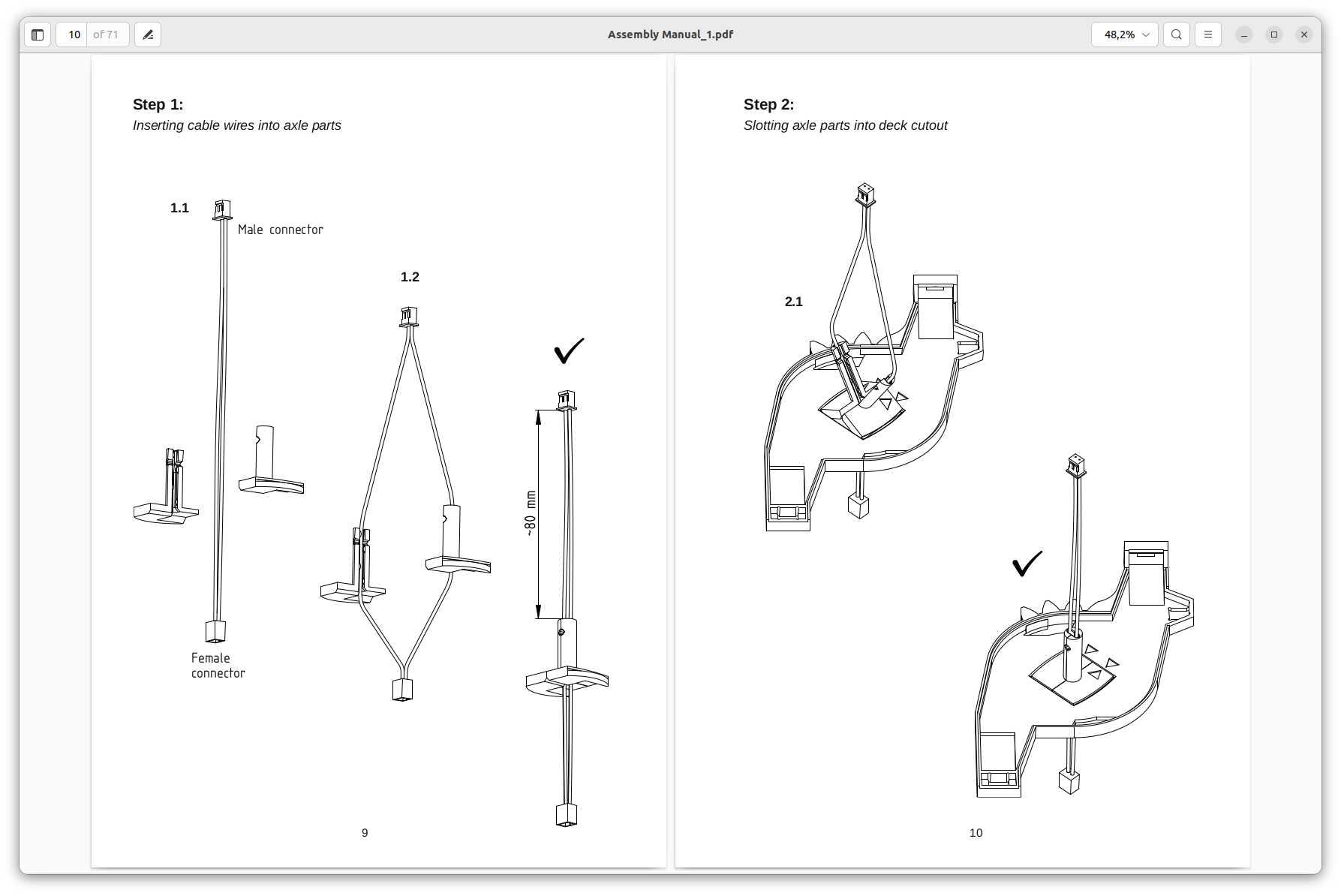
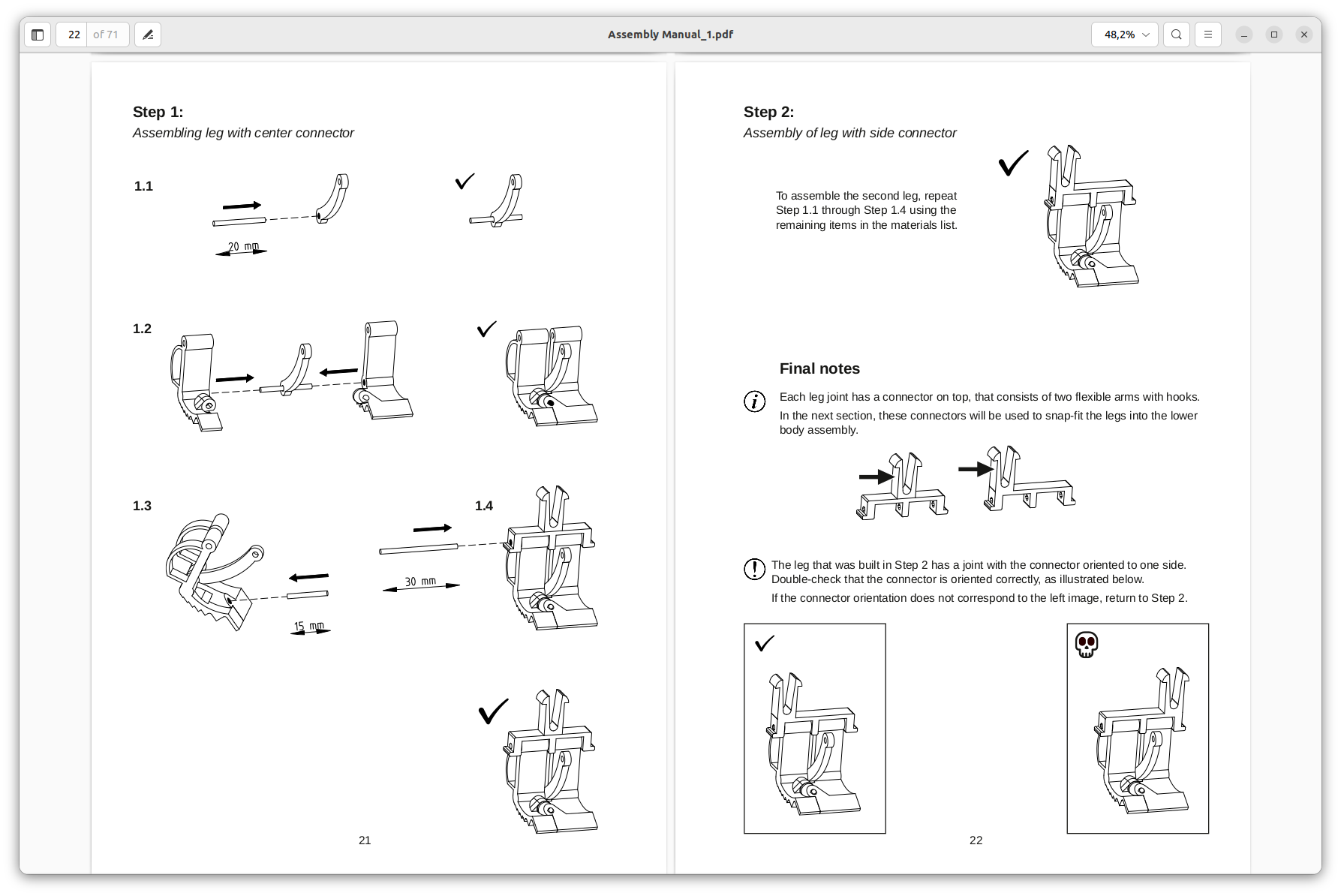
    Finally got around to making a proper assembly manual for the robot.

    Manual is available on GitHub: https://github.com/dejanristic78/Tardygrade-assembly-manual.git 

    A few example pages out of the manual: 

    Initially I wanted to emulate the style and philosophy of IKEA furniture assambly manuals, where everything is explained by simple drawings. But I realized along the way that some additional text explenation were necessary.

    Page layout made in Scribus 1.5.8.

    Illustrations were made in FreeCad, using the TechDraw workbench.

    If you decide to build the robot using the manual, let me know your results.

  • Parametric 3D models to fit various types of servo horns

    Dejan Ristic11/27/2021 at 22:20 0 comments

    It seems there's no agreement among hobby servo manufacturers on what exact dimensions their servo horns should be. You'd think it would be the easiest thing in the world for them to all make their horns according to an agreed upon standard, but apparently this is not possible for some reason.

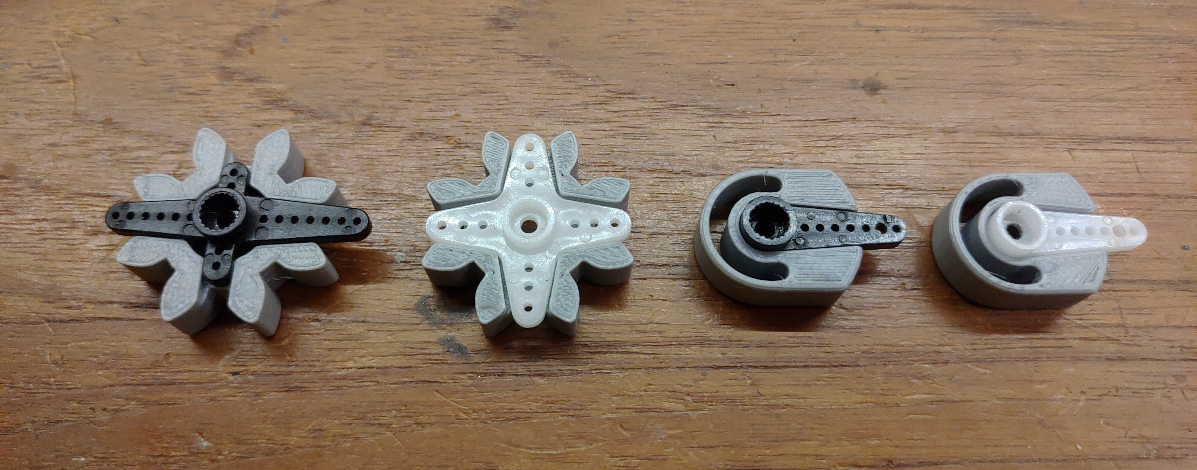
    This state of things has presented me with a problem, since the two 9g servos that drives Tardygrade needs to fit their horns into precisely dimensioned slots in the 3d printed gears.

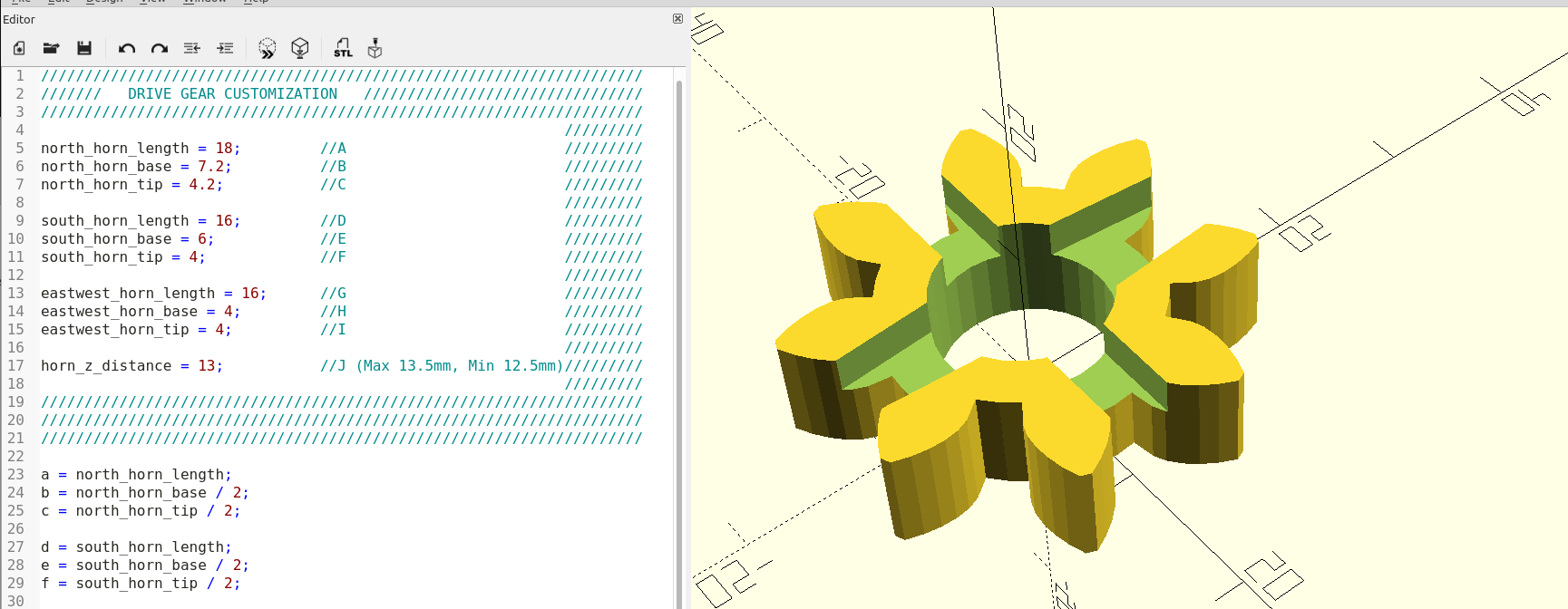
    To remedy this I made two parametric OpenSCAD scripts that lets you customize the gear parts that slots the servo horns. One simply need to take some measurements of the horn with a caliper and enter them into the script. Then the resulting stl should be a perfect fit for that particular servo horn. 

    I used FreeCad to model the the gears. These models are then imported into the OpenSCAD script, which is only responsible for making the customized cutout for the servo horn.

     Yep. Works pretty well.

  • Smooth operator

    Dejan Ristic10/15/2021 at 21:11 0 comments

    Improved servo action using the esp32 remote control module (and a tiny bit of math)

    The Tardygrade turning gear mechanism is designed to allow the robot to pivot 15° at each step. In theory this will let it pivot a full 360° within twelve full revolutions of the main gear.

    But there's a snag. The servo moves at linear speed, resulting in abrupt acceleration and deceleration. This can make the feet loose their grip and slide about, which means pivoting the robot to a precise degree becomes impossible.

    After becoming aware of this issue I made a brief attempt to introduce smooth endpoints to the servo action. But since I couldn't immediately figure out how to put that into code I threw it in my mental basket marked "annoying little bugs I'll probably get around to fix sometime".

    Now I figured would be a good time to pick something out of that basket instead of putting more stuff in.

    I had bookmarked [James Brutons] video on how to make robots move smoothly (which I probably found on the Hackaday blog originally).
    Although the method he used was elegant, it only provided smooth deceleration. I needed smooth acceleration as well. 
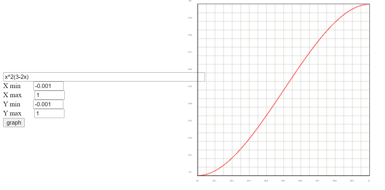
    The comment section steered me in the direction of cosine interpolation—thanks YouTube user [Cole Smith]. Then this post on the CodePlea blog "refreshed my memory" on how to do it, and also covered an alternative that doesn't involve cosine.

    in the end the math required was as simple as: x^2(3-2x)

    Now, all of this worked well enough when using the machine.PWM library. However there's some considerable loss of duty cycle resolution since that library only deals with integers.

    But by being a frequent lurker on the micropython.org forum I'd been made aware of an alternative, thanks to user [wangshujun].
    The ESP32 RMT module is intended for IR remote control communication, but can really be used for any kind of pulsed data. It's accesseded through the esp32.RMT library.

    Using RMT instead of the PWM library brings two advantages: One is higher duty cycle resolution. The second is that the entire pulse sequence can be offloaded to hardware, which is an ideal way of making the servo action non-blocking. This will allow the robot to be more responsive when controlled by remote. It can also make life simpler when adding new functionality like AI and such.

    While I was at it I saw no reason why not to use the RMT module to control the other servo as well. While not as dramatic of an improvement, that allows me to easily achieve gradual changes in walking speed, which is a nice feature to have.

  • Bugfixes for PCB v0.3

    Dejan Ristic10/12/2021 at 17:14 0 comments

    I've meandered through a few weeks of low activity, but I finally had time to track down the bugs that arose when I tested out my most recent PCB revision. 

    First bug was the power switch MOSFETs that didn't seem to work as expected. 

    That turned out to simply be caused by a coding error. When I shuffled around the GPIO pins there was a stray line of code left that gave rise to some hard to diagnose problems.

    The second bug was specific to the Adafruit HUZZAH32 dev-board. Two of the hall switches didn't trigger as expected like they would when using the TinyPICO dev-board.  

    This was due to me not reading the datasheet closely enough. To save on external components I use the ESP32 internal GPIO pull-ups to hold the output of the hall switches high. But it just so happened that those two particular GPIO pins didn't have any pull-ups. That was a face-palm for sure. Actually both of these issues were very avoidable.

    No matter. I've updated the pcb design and sent it off to fabrication today. Expect to get the boards end of next week.

    In the meantime there are plenty of loose ends to tie up in other areas of the project.

  • Showcasing the new prototyping shield

    Dejan Ristic10/06/2021 at 04:00 0 comments

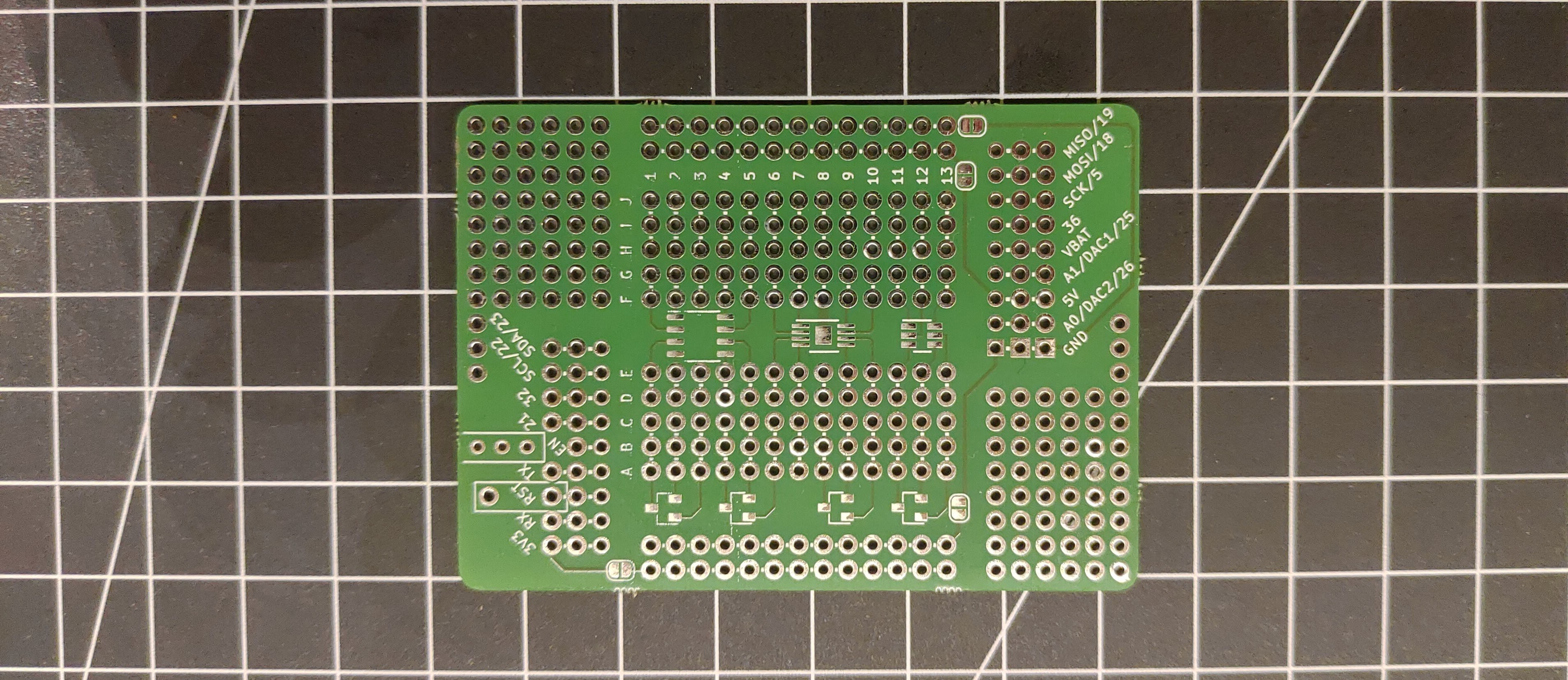
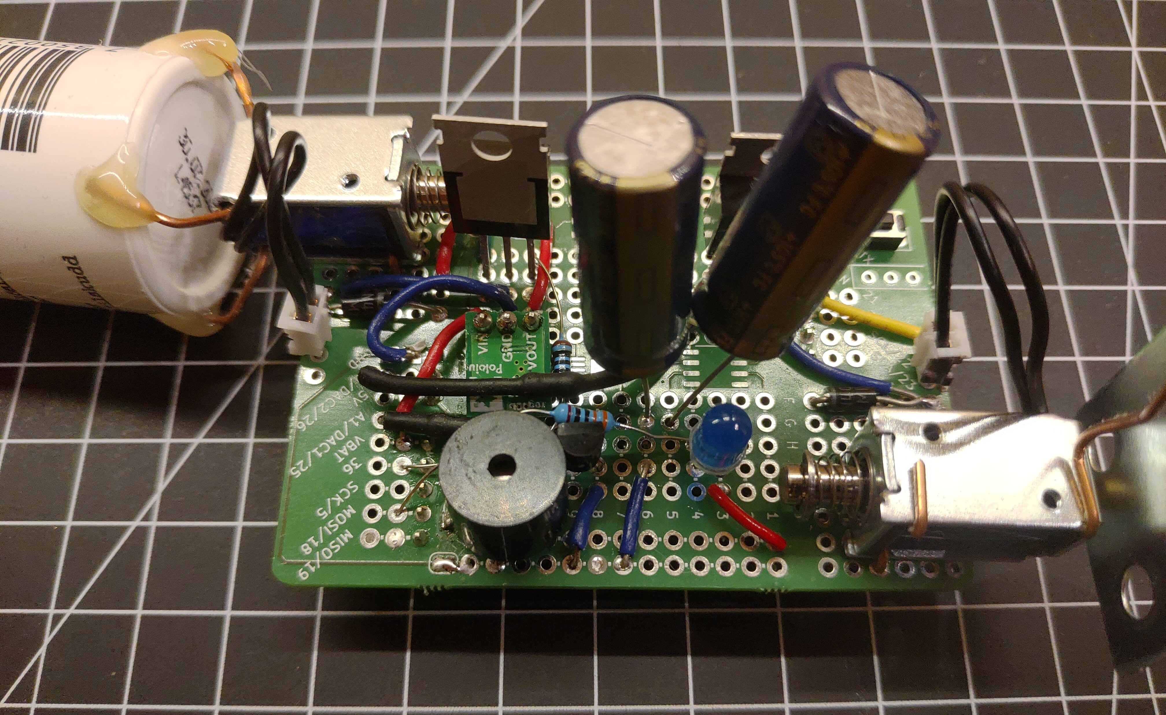
    The Tardygrade prototyping shield is a general purpose perfboard pcb that fits on top of the robot and breaks out the unused GPIO pins of the ESP32.

    Here I have utilized it to build a little solenoid drum machine that adjusts its tempo to the walking pace of the robot.

  • Tardygrade is now on GitHub & Discord

    Dejan Ristic09/27/2021 at 19:48 0 comments

    I've created some GitHub repos for the 3d model and pcb:

    https://github.com/dejanristic78/Tardygrade-BOM

    https://github.com/dejanristic78/Tardygrade-pcb

    https://github.com/dejanristic78/Tardygrade-3d-model

    https://github.com/dejanristic78/Tardygrade_stl_files

    Firmware repo is on my to-do list.

    I will include the appropriate open source license when the project nears completion. For now, anyone can download and experiment with these files for personal use.

    Please beware that the robot is still being developed and is not yet production ready. If you would like to build it yourself, and perhaps provide me with feedback while doing so, you are welcome to join the Tardygrade Discord server. PM me for details.

  • New pcb test run

    Dejan Ristic09/26/2021 at 21:47 0 comments

    The new controller pcb has passed the walking test. Hooray!

    However there seems to be a weird issue with the power supply MOSFET:s. I will devote a later post to it when I've had time to investigate. 

  • New PCB & prototyping shield

    Dejan Ristic09/14/2021 at 21:25 0 comments

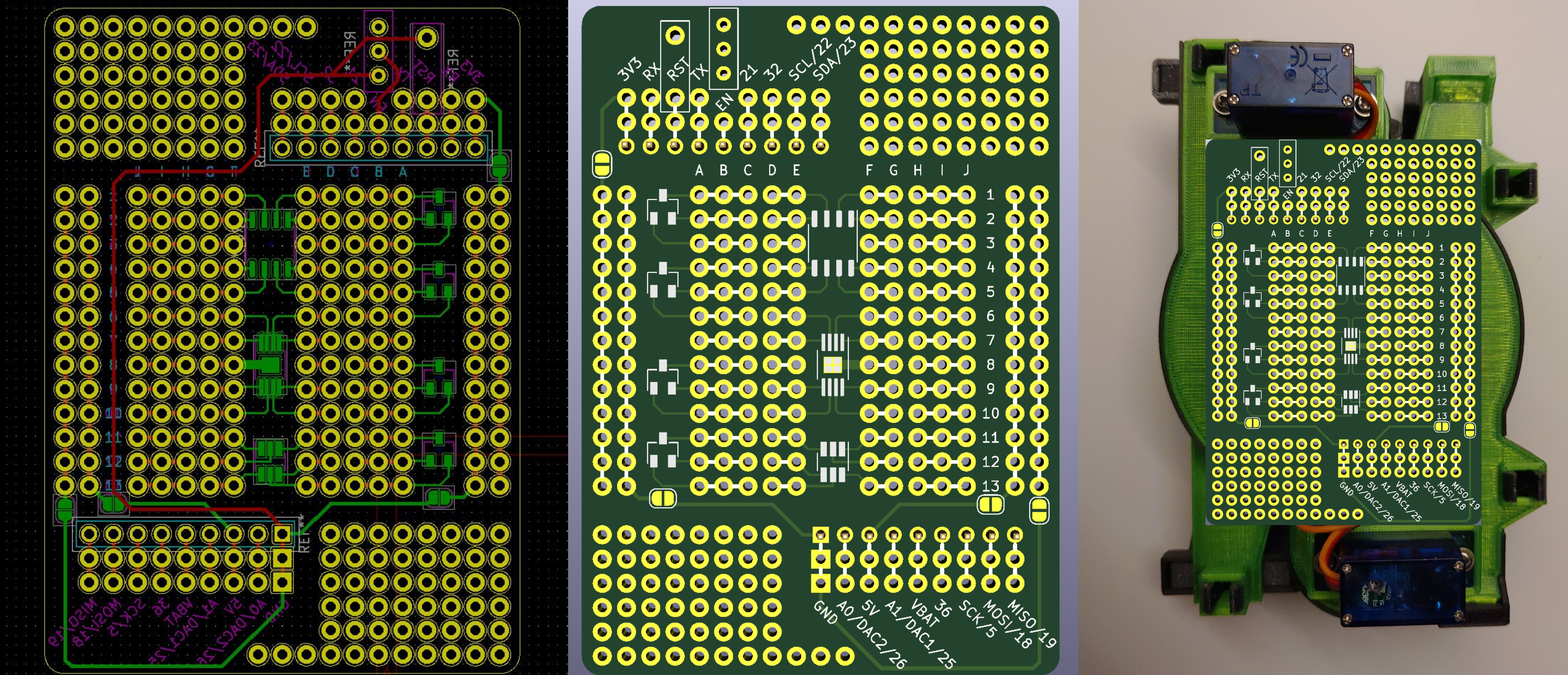
    Here's the new v0.3 pcb design. Layout has been adjusted to accommodate the change to AH1815-W-7 hall switches.

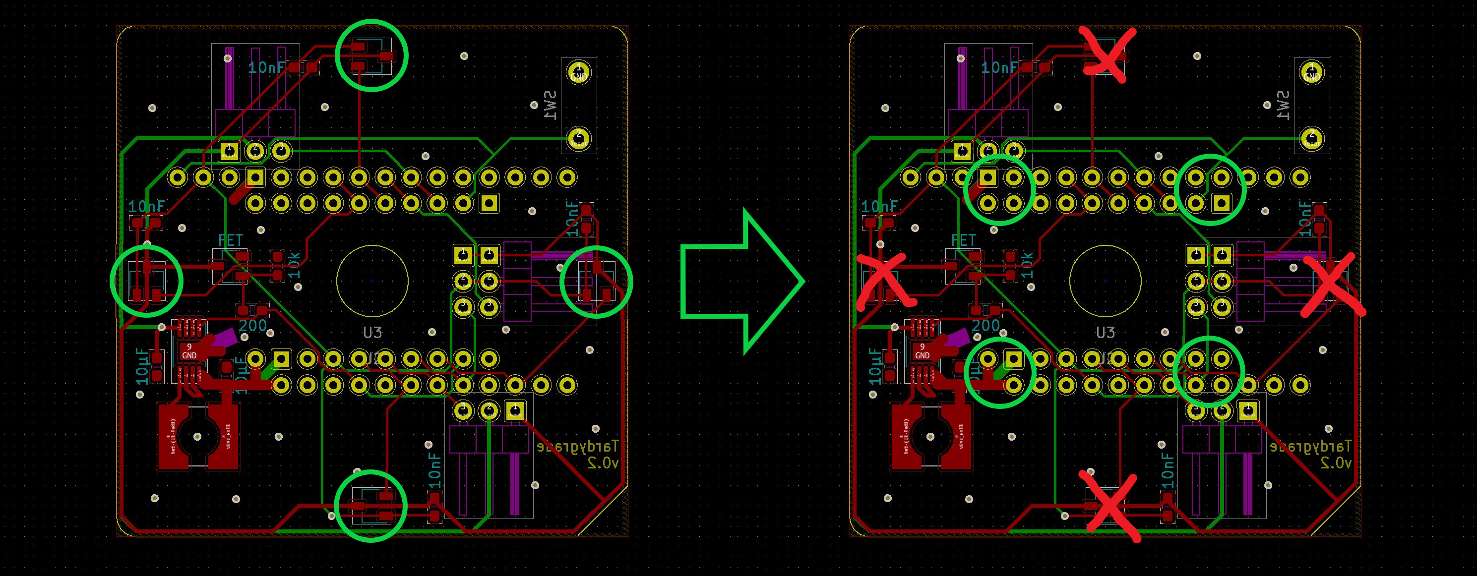
    Since the hall switches needed to be placed on a smaller radius I had to rotate the esp32 board headers by 45°.
    Hand soldering the board will be a bit more difficult since everything is a bit more cramped. But overall I'm satisfied with this layout.

    New for this iteration is an expansion shield that fits on top of the controller PCB. It's a through-hole prototyping board that breaks out the unused GPIO from the esp32 board. I also threw in some smd footprints for good measure.

  • Switching switches

    Dejan Ristic09/01/2021 at 17:12 0 comments

    Quick recap

    The global chip shortage snatched away the "ultra high sensitivity" hall switch I was planning on using for the Tardygrade controller pcb. So now I need to make do with a non-ultra alternative. 

    What the consequences are

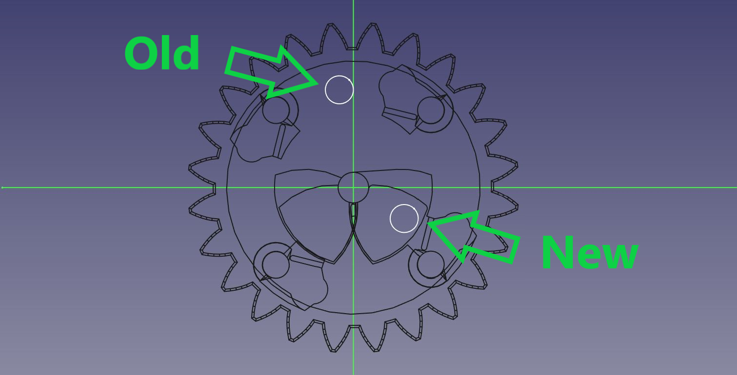
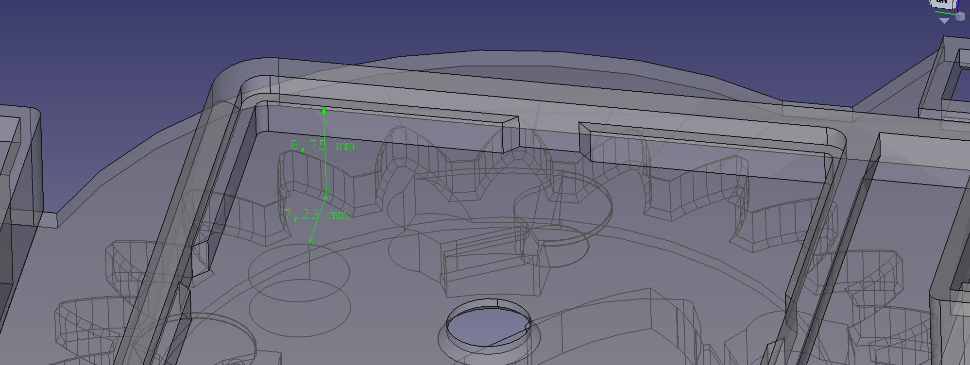
    Due to the lower sensitivity of the new IC I needed to move the magnet in the main gear closer to the controller pcb in order for it to be detected. The old design had the magnet embedded inside the body of the gear, which allowed me to place it at any angle with respect to the cams. This allowed me to layout the pcb as I pleased, since the magnet position could be adjusted to fit the layout of the hall switches.

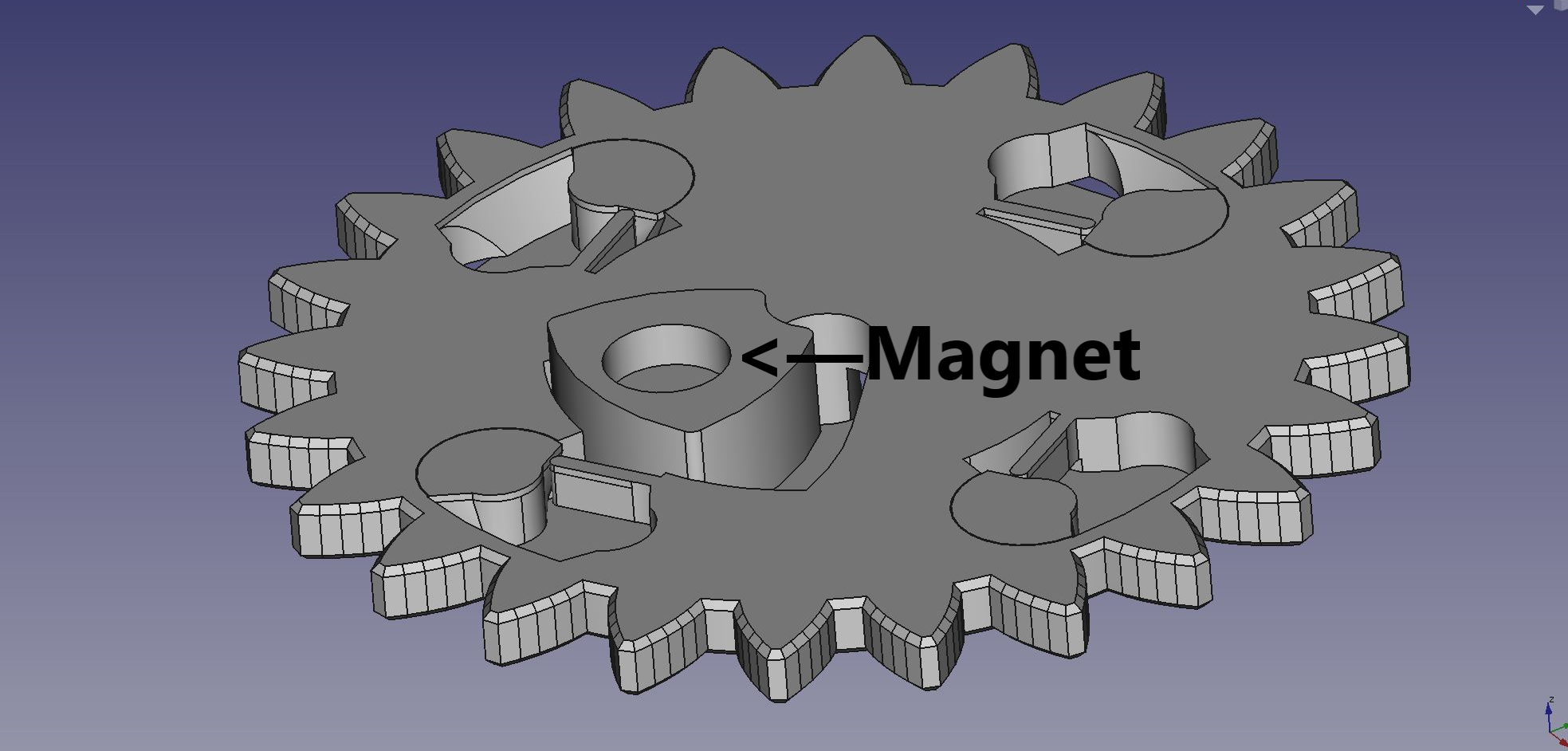
    The only way to get the magnet closer to the pcb is to slot it into the upper cam. But that also means I'm committing to a specific radial placement of the magnet, which leaves me with only one way of placing the hall switches.

    New position of the magnet.
    New position of the hall switches. Layout of the pin headers and all other components will need to change as a consequence.

    What to do about it

    For the next pcb prototype I'll turn the pin headers for the ESP32 board to a 45° slant in order to make room for the hall switches. But before ordering new boards I wanted to test the whole concept in practice by retrofitting one of my current prototype boards. 

    With the use of hot glue and some tricky soldering I transplanted the hall switches to coincide with the new magnet path. I then mounted the pcb at a diagonal to simulate the new hall switch placement.

    Shoddy as hell.

    The result

    I'm happy to report that this setup worked out well in testing. The magnet was being detected consistently, which was the main thing I was worried about. Accuracy seems to be as good as before or perhaps even a bit better. Maybe that has to do with the "edge" of the magnet field being less diffuse at a shorter distance, but that's just my speculation.

    In conclusion 

    Crisis is averted. Project still alive and kicking.

  • I didn't think it would happen to me

    Dejan Ristic08/12/2021 at 00:03 0 comments

    I'm now officially a victim of the component drought of 2021. But I will persevere.

    The PCB for Tardygrade is as simple as can be. The most exotic components on it are four surface mounted hall switches. They detect the position of a magnet embedded in the main gear, which lets the uC know the position of the robots legs. 

    When designing the first PCB prototype I had whittled the choice of hall switches down to two options:

    These were both hand solderable and not too expensive when bought i bulk. Since the magnet is fairly far away from the sensors (almost 9 mm) I went with AH9246, which is branded as having "ultra high sensitivity".

    Two weeks later I received the PCBs and after having added some botch wires everything ended up working as expected.

    I then started working on a new improved PCB. I browsed Mouser for components, and noticed that the stock of AH9246 was down to 3000. 

    Didn't there use to be around 8000 last time I checked? And factory lead time was 18 weeks. Hmm, better stock up before they run out. 

    Naah, I'll do it tomorrow. 

    Next day it was down to 0.

    I checked on my second option AH1815. They were running low too so I cleared out Mousers remaining stock of about 1000 units. They were a bit cheaper anyway and required fewer external components. But at this point I had somehow forgotten all about the difference in sensitivity and just assumed that the AH1815 would work as a drop in replacement for AH9246.

    Well, turned out it didn't. The AH1815 wasn't even close to detecting the magnet at that distance. And at the time of writing factory lead time for the AH9246 is almost a year ( ! )

    But I think the situation can be salvaged with a minor redesign of the main gear and PCB.

    Instead of being embedded inside the gear body, the magnet will be slotted into the upper cam of the gear. This puts it right up against the ceiling of the chassis, and much closer to the hall switches. Seemingly close enough for the magnet to get detected.

    There's and issue with that solution however: 

    With the old magnet placement the hall switches could be placed along the front, rear, left and right edges of the board. But a magnet placed in the cam will be at a diagonal of the board for each of the four relevant leg poses. This, in combination with the fact that the magnet now traces a smaller circle, means that the hall switches would overlap the uC pin headers, using the current layout.

    So what I may need to do is to rotate the headers for the uC boards, to make just enough room to fit the four hall switches on the bottom of the PCB.

    Well, it's not the worst thing in the world. Might even look cool. And at least I'm now stocked up with hall switches for the foreseeable future.

View all 21 project logs

Enjoy this project?

Share

Discussions

Mike Rigsby wrote 10/08/2021 at 00:46 point

Congratulations on being a winner in the robots challenge--great project!

  Are you sure? yes | no

Dejan Ristic wrote 10/09/2021 at 11:04 point

Thanks!

:-)

  Are you sure? yes | no

Similar Projects

Does this project spark your interest?

Become a member to follow this project and never miss any updates