-
1Some assembling tips
The Solidworks assembly and the BOM should be a good starting point for anyone willing to replicate the project. The "closed frame" design allows for some manual adjusting of the distance between the steppers, so it is easier to find the "seet spot" where the oscillating motion works at its best.
Once you get a DLP lightcrafter, set up all the controling software (link in the components list), you will need to upload the 96 slices, set it up with trigger signal coming from an Arduino or similar board, or directly from the TMC1141.
-
21) CNC / laser cutting the plexiglass parts
- CNC / laser cut the plexiglass parts "Ala laterale v1" --> 4 pieces needed. I used 3mm black acrylic / plexiglass.
- CNC / laser cut the plexiglass parts "Central plate v1" --> 2 pieces needed. I used 3mm black acrylic / plexiglass.
- CNC CUT the part "inner central plate". This part cannot be laser cut, because ther are slots and other features that require to be able to control the Z axis when manufacturing. 3mm transparent / frosted acrylic / plexiglass --> 2 pieces needed.
- CNC cut or 3d print the file "VVD_04_PlexiSostegno_v2" --> 1 piece
- CNC / laser cut the plexiglass part "basr1". 3mm black acrylic / plexiglass --> 1 piece
- CNC / laser cut the plexiglass part "usb_plate". 3mm black acrylic / plexiglass --> 1 piece
- CNC / laser cut the plexiglass part "dwn_plate1". 3mm black acrylic / plexiglass --> 1 piece
- CNC / laser cut the plexiglass part "pwr_plate". 3mm black acrylic / plexiglass --> 1 piece
- CNC / laser cut the plexiglass part "SingleSideElement". 3mm black acrylic / plexiglass --> 26 pieces needed.
-
32) 3D Print the parts
3d print the parts:
- "Connettore piastre side" (14x)
- "StepperCap" (2X)
- "Connettore Piastre side shorter" (6x)
- "AstaMonopezzo1Mot" (2x)
either with FFM, FDM, SLA, sintering,
-
43) Back and front assembly
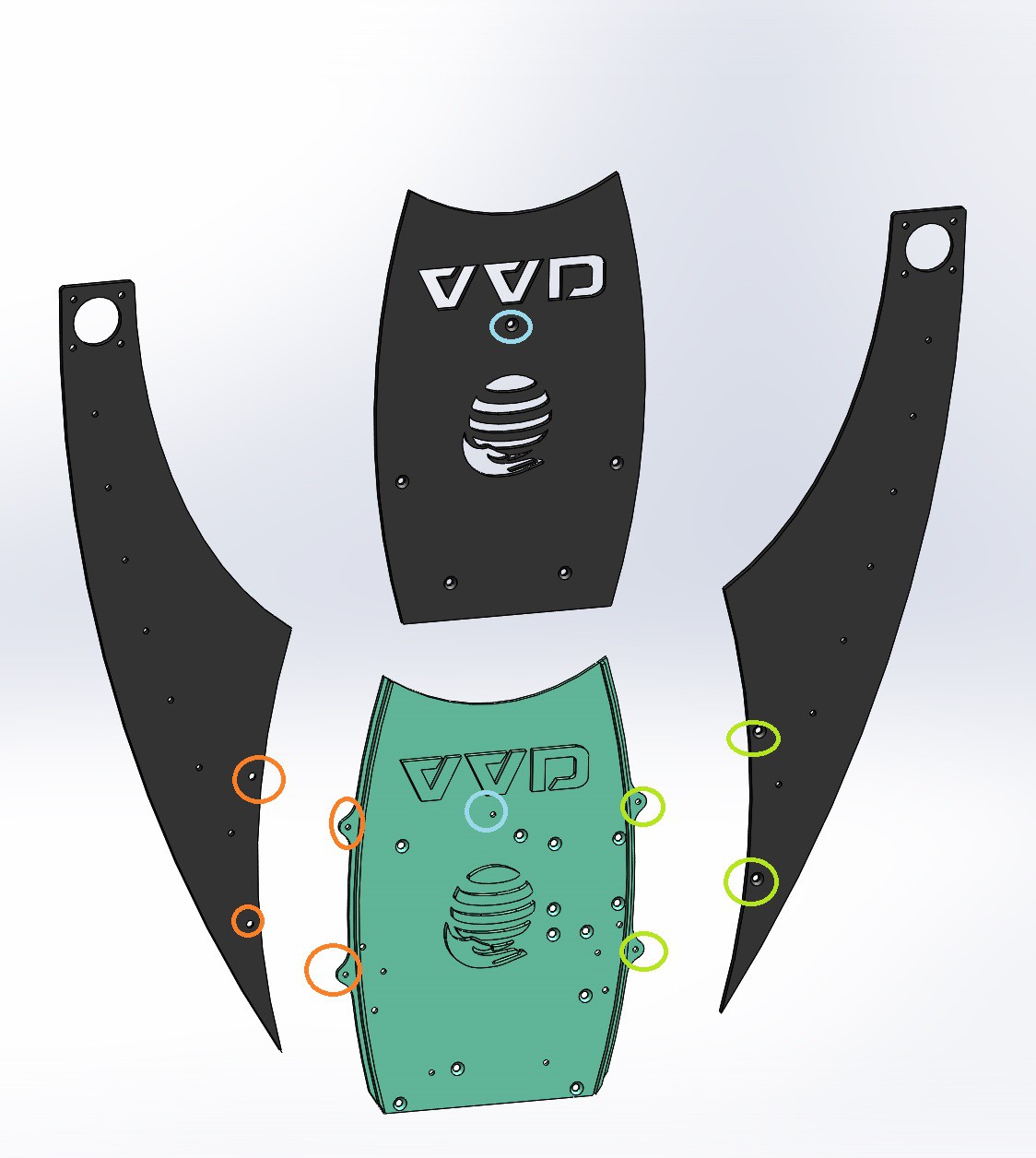
With M3x6mm screws (you can use countersunk black screws for better look), assemble one back and one front assembly as in the following picture. The "central plate v1" must be attached onyl at the end of the whole assembly.
![]()
-
54) Side elements assembly
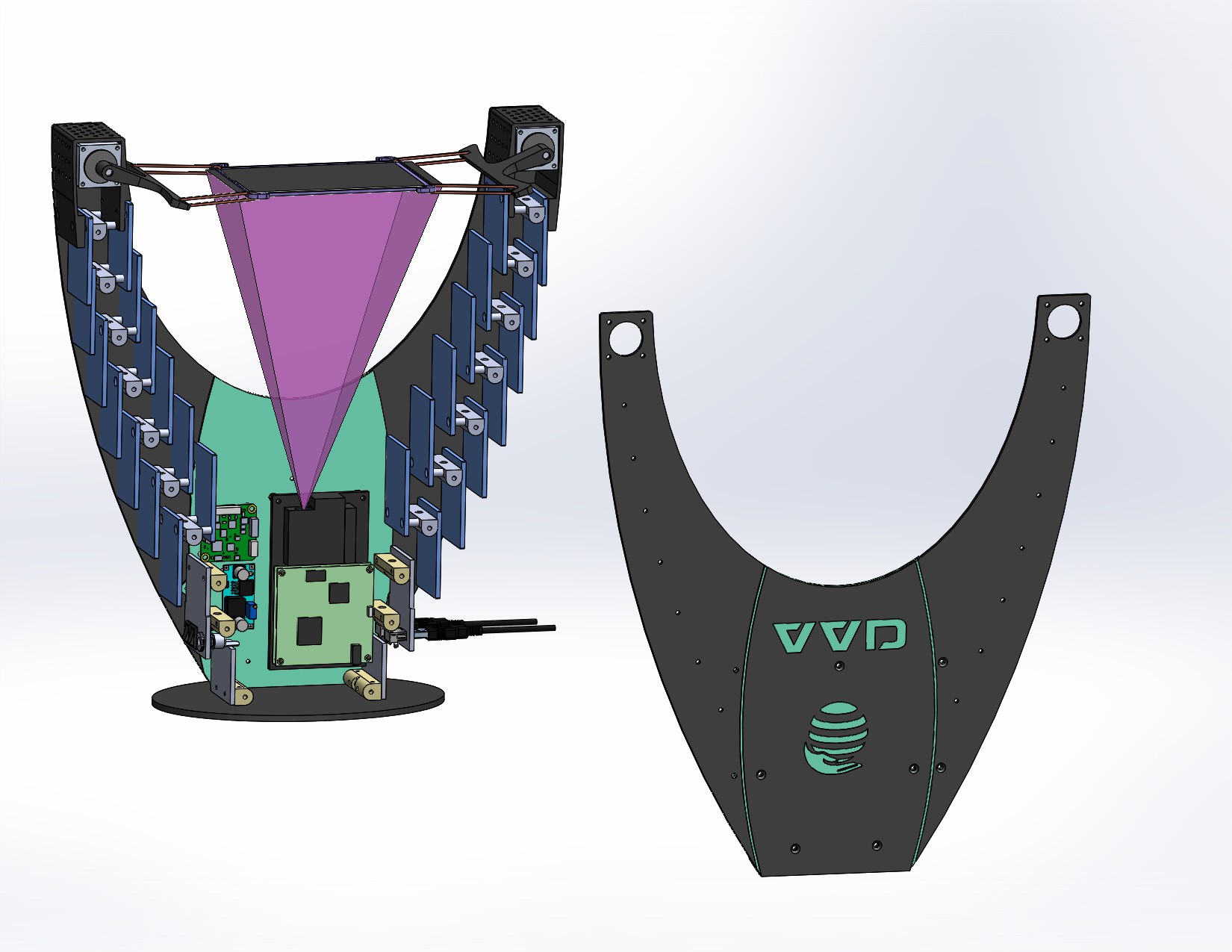
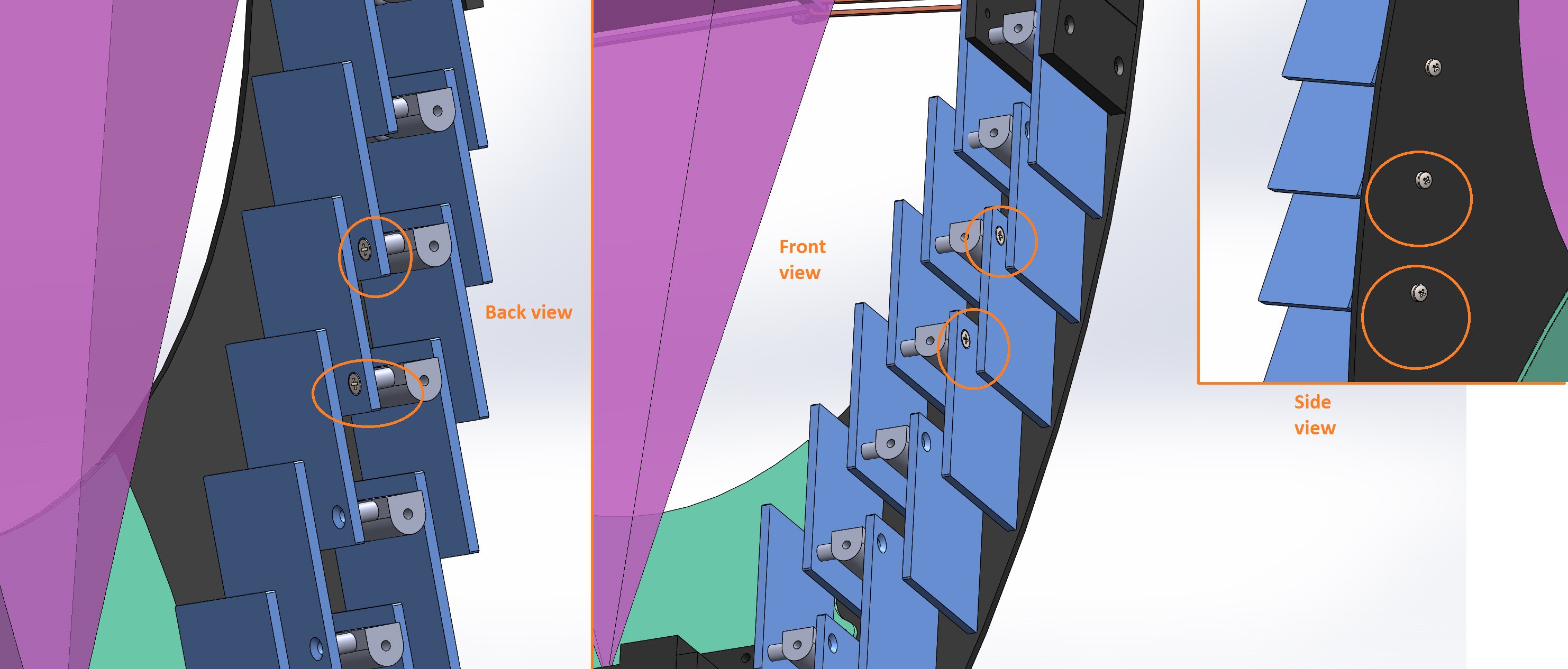
As in the following picture, assemble the back assembly with the side elements, with M3 screws.
-
65) Mount projector, stepper driver, Dc converter
Use M3x12 spacers to mount on the back assembly the Projector, the TMCM1141, and the LM2596.
Adjust the Lm2596 to get input=24V, output 5V, before mounting it.
-
76) USB and Power connections
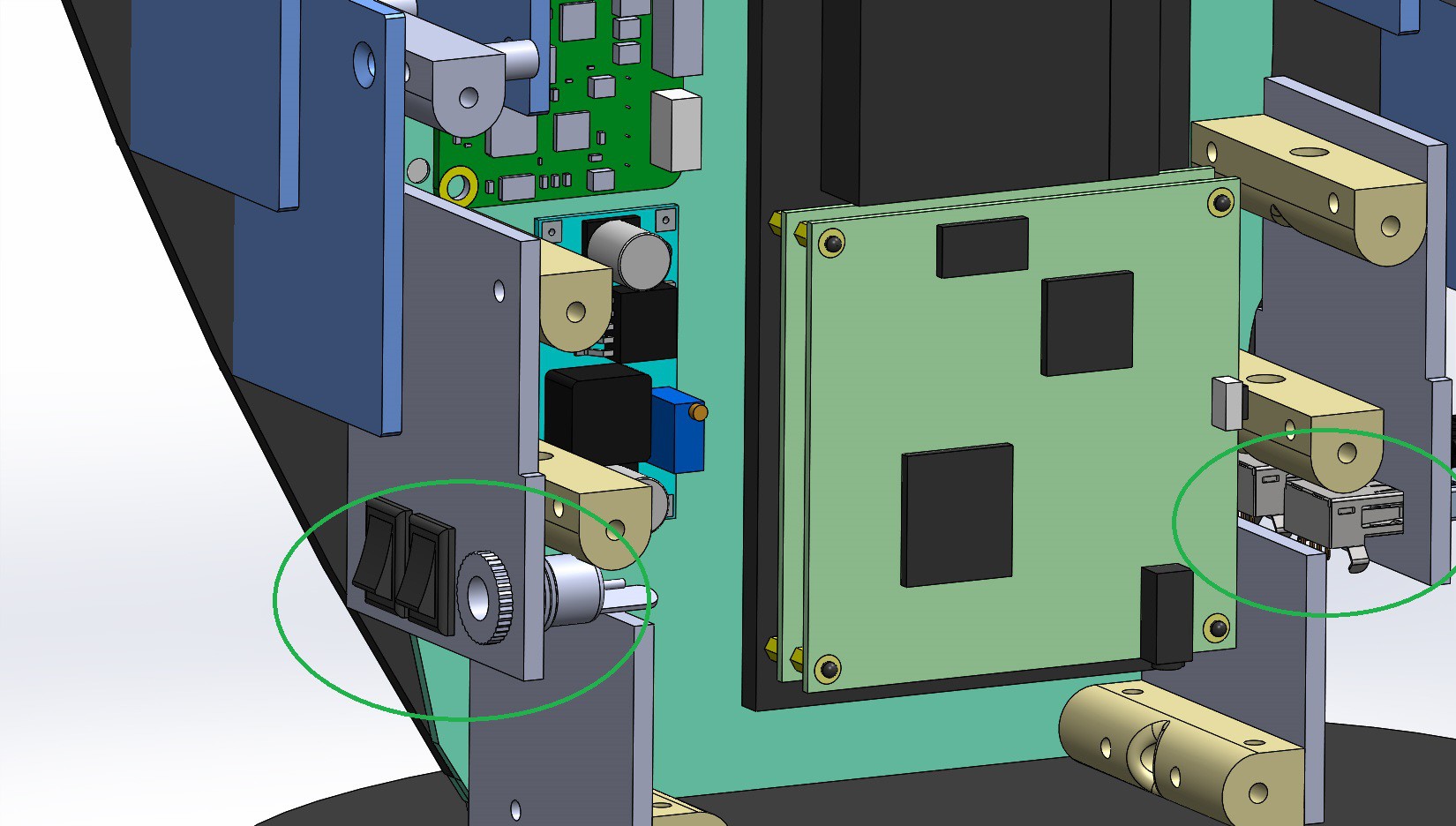
Press fit the USB connectors, DC jack, power switches. I used glue gun to fix them in place after inserting.
-
87) Preparing the projection area
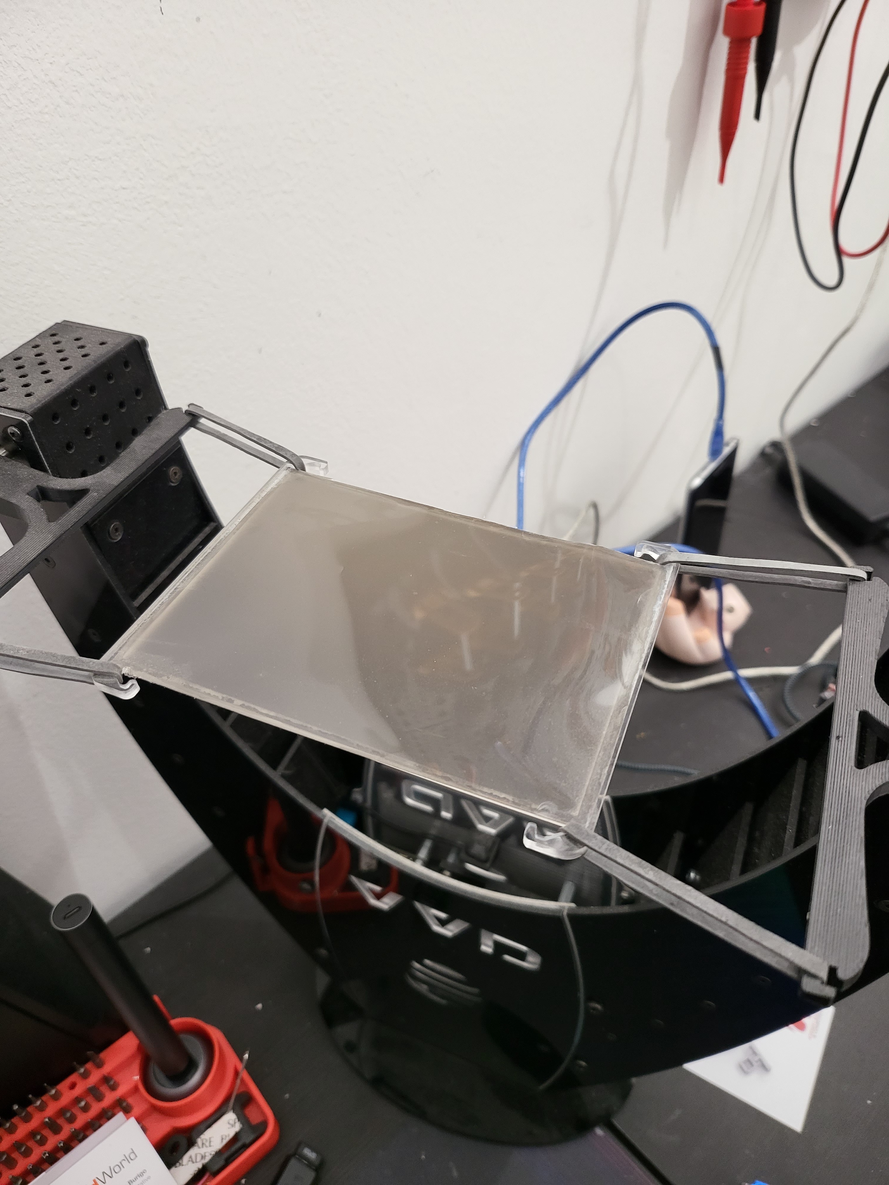
Cut a rectangle 120x87mm on the rear projection film. Glue it to the top of the "VVD_04_PlexiSostegno_v2" part.
It will be tensioned by 4 rubber bands, one on each corner, connected to the 2 swinging arms.
![]()
-
98) Connections
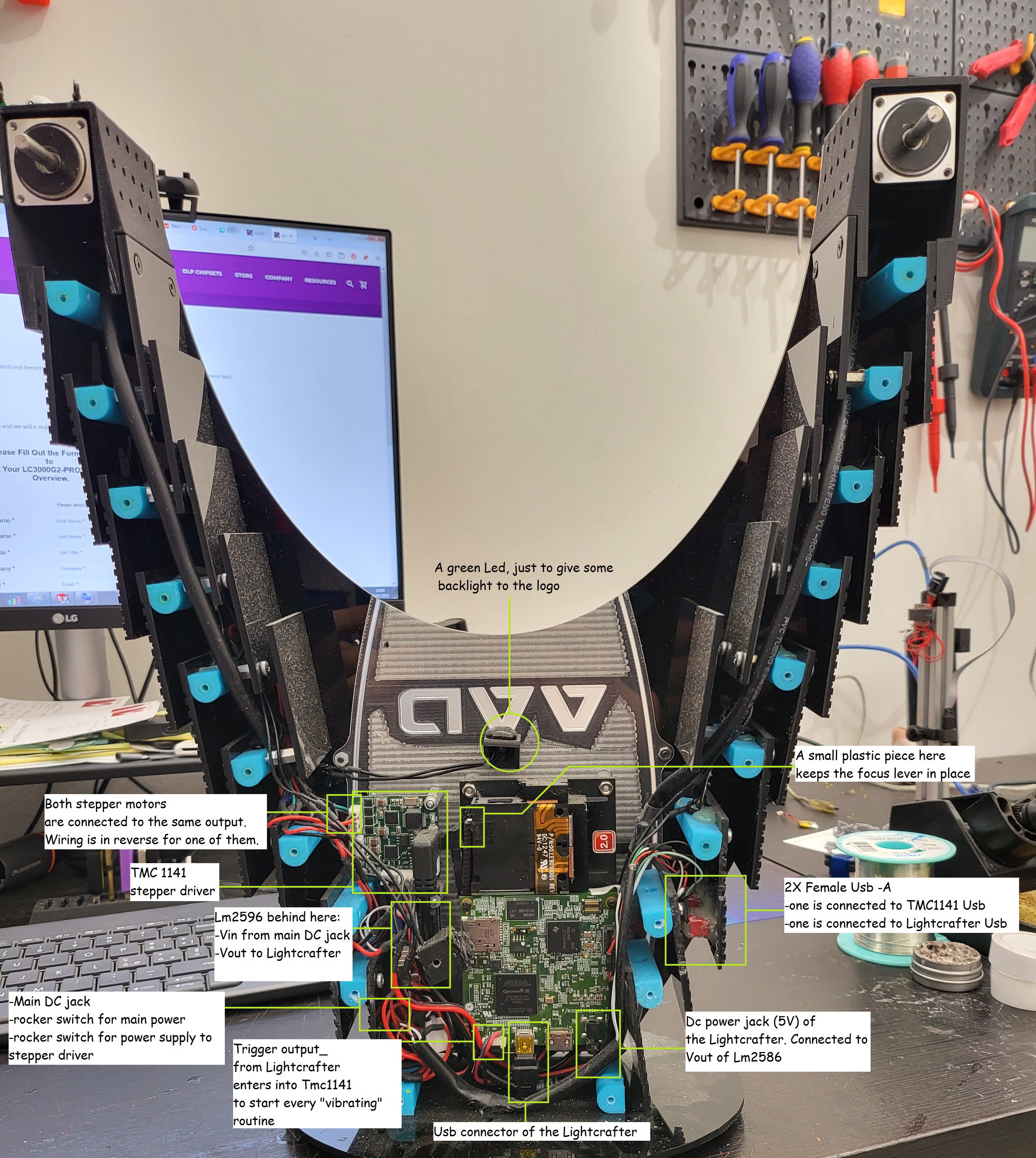
An internal cable must be assembled that inserts into the USB connector of the Projector, and connects to one of the female Usb-A ports on the side of the VVD.
Another internal cable must be assembled that inserts into the USB connector of the TMCM1141, and connects to the other female Usb-A port on the side of the VVD.
DC jack of the VVD connects to both power line of the TMCM1141, and DC IN on the Lm2596.
LM2596 dc output of 5V is the power supply of the Projector. Another cable must be assembled here.
TMCM1141 output controls both steppers, wired in opposite direction.
![]()
-
109) TMCM programming
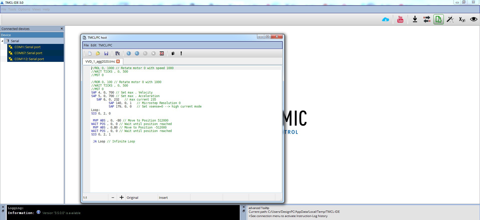
Download the software https://www.trinamic.com/support/software/tmcl-ide/ to program the TMCM1141.
Use the firmware files in the "files" section. Programming is done via Usb, once.
![]()
VVD: an open source Real 3D Volumetric Display
Your 3D content on a real PoV volumetric display, no glasses needed!
 Madaeon

Discussions
Become a Hackaday.io Member
Create an account to leave a comment. Already have an account? Log In.