Uri Shaked
-
Logic Analyzer Debugging
07/14/2021 at 22:06 • 0 commentsA quick tip to help you debugging your projects: you can use the virtual logic analyzer to view the signals generated by your PIO machine!
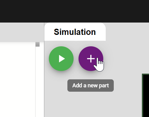
Add a logic analyzer to your project by clicking on the purple "+" button and selecting "Logic analyzer (8 channels)":
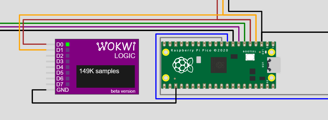
Then connect pins D0 / D1 to your DATA / SYNC lines (these are Pico pins GP2 / GP3 if you use the tv-pong project template).
Start the simulation, and you should see the Logic Analyzer's green activity LEDs blink as the data is coming in, as well as the number of samples collected:
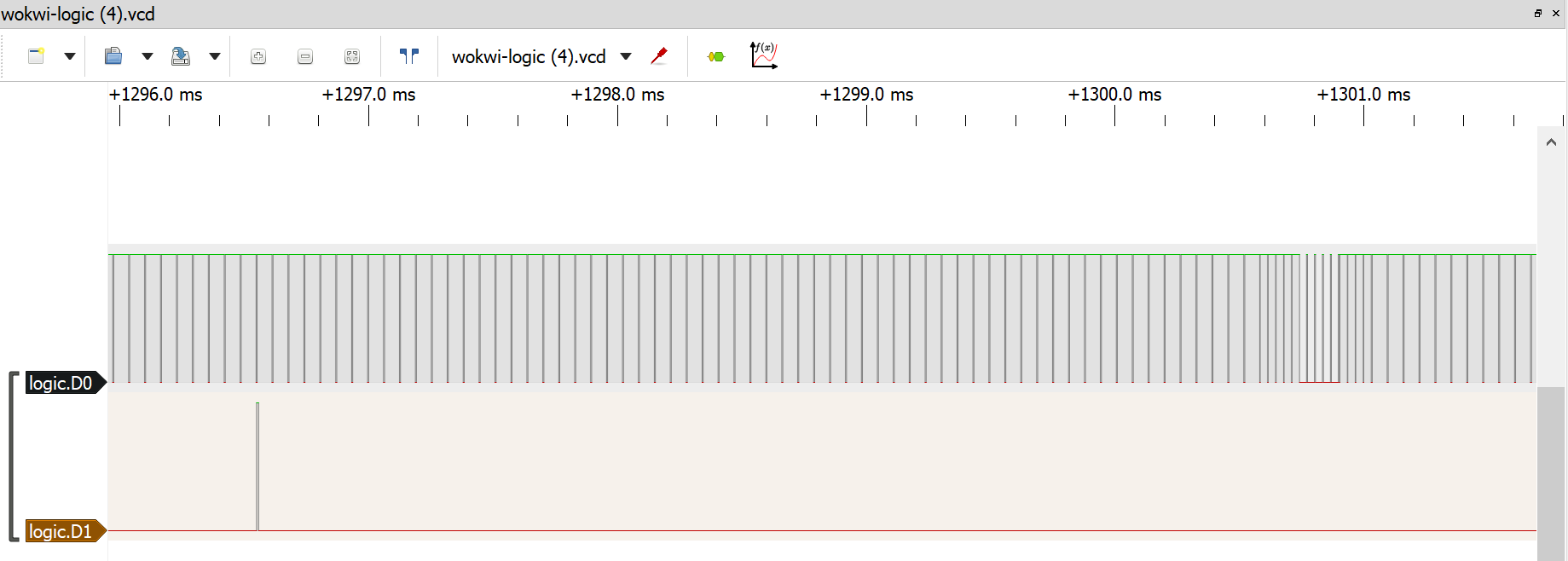
When you stop the simulation, the Logic Analyzer will download a VCD file with the recorded signals to your computer.
You can use PulseView to open the file and view the recorded signals:
For more information and detailed instructions on how to load the signal file into PulseView, check out the Logic Analyzer guide.
-
How to approach the project
06/25/2021 at 18:10 • 0 commentsThe Pi Pong project is not easy, and can even be overwhelming. It takes time and practice to wrap your head around the programming model of the Pi Pico's PIO, and it could be difficult to swallow this project in a single bite.
You can find here a step-by-step breakdown, which can guide you through the implementation of the project. It's totally optional - use it if you want, or just go on your own.
Step 1 - White Screen
Fill the screen with white color. At minimum, you'll need to drive the DATA signal high, and generate at least one Long Vertical pulse, followed by a series of Horizontal sync pulses.
And in pseudo code:
SYNC ← HIGH
Repeat forever:
  SYNC ← LOW
  wait 30us
  SYNC ← HIGH
  wait 2us
  repeat 300 (or a similar number) times:
    SYNC ← LOW
    wait 4us
    SYNC ← HIGH
    wait 60us
I suggest coding the SYNC signal driving logic into a PIO machine, so you get precise timing.
Step 2 - Half white
It's time to take control of the DATA line too! Make it go HIGH about 6 microseconds after the end of the Horizontal Sync signal, then LOW again after ~22 microseconds.
You can start with controlling both DATA and SYNC using a single PIO machine, and then move on to controlling them with two distinct machines that synchronize using the IRQ and WAIT instructions.
Pseudo code:
DATA ← LOW
SYNC ← HIGH
Repeat forever:
  SYNC ← LOW
  wait 30us
  SYNC ← HIGH
  wait 2us
  repeat 300 (or a similar number) times:
    SYNC ← LOW
    wait 4us
    SYNC ← HIGH
    wait 10us
    DATA ← HIGH
    wait 22us
    DATA ← LOW
    wait 28us
Step 3 - Frame buffer
Instead of hard-coding the data line to stay HIGH for the first half of each line, we'll let the program feed the data. I suggest starting with 32 bits (pixels) per line (not so great resolution, but still usable), then going up to 128 or even 256 bits.
The idea is to have two PIO machines: one will drive the SYNC signal, and the second one will pull the data from the program one 32-bit word at a time, and then drive it to the DATA signal. Using the "Autopull" PIO setting is highly recommended!
Your program will start both PIO machines, then feed the data to the Data machine. I suggest creating a buffer with the screen contents (frame buffer), and then repeatedly copy data from this buffer into the TX FIFO of the DATA-driving PIO machine. You can feed the data using an interrupt handler (either TXNFULL interrupt/IRQ triggered explicitly by the PIO machine code).
Note: I recommend using C++ (Arduino core) for the game. But if you do use MicroPython, define your interrupt handler as a hardware interrupt (pass "hard=true" when defining the handler). Note that there are some limitations for what you can do inside an interrupt handler: for instance, memory allocation isn't allowed.
Note 2: Ideally, you can use the DMA controller to automatically feed data from memory into your Data machine. DMA is currently not supported in the emulator, but this will probably change in a few weeks. Until then, you can try the DMA approach with a physical Pi Pico and PAL TV (or logic analyzer).
Sync machine pseudo code:
SYNC ← HIGH
Repeat forever:
  SYNC ← LOW
  wait 30us
  SYNC ← HIGH
  wait 2us
  repeat 300 (or a similar number) times:
    SYNC ← LOW
    wait 4us
    SYNC ← HIGH
    Trigger IRQ (to notify the Data machine)
    wait 60us
Data machine pseudo code:
Repeat forever:
  DATA ← LOW
  Optionally trigger an IRQ to notify the code we're ready for more data
  Wait for an IRQ from the Sync machine
  PULL 32-bit word from the TX FIFO
  Shift the one bit at a time through the DATA pins
Step 4 (optional) - Perfection
At this stage, the PAL TV driver should be ready for you to use in your code! All you have to do is to write the pixel data to the framebuffer, and the PIO machines will take care of generating the right signal.
However, the SYNC signal is not perfect yet. It's working in the simulator and is good enough for this assignment. But if you want to get it perfect (perhaps you want to try it with a real TV), you are definitely invited to do so! I included here some pseudo code to help with that:
Sync machine pseudo code:
SYNC ← HIGH
Repeat forever:
  If odd frame:
    Repeat shortSync() six times
    Repeat longSync() five times
    Repeat shortSync() five times
  Else (even frame):
    Repeat shortSync() five times
    Repeat longSync() five times
    Repeat shortSync() four times
  Repeat horizontalSync() 305 times

shortSync():
  SYNC ← LOW
  wait 2us
  SYNC ← HIGH
  wait 30us

longSync():
  SYNC ← LOW
  wait 30us
  SYNC ← HIGH
  wait 2us

horizontalSync():
  SYNC ← LOW
  wait 4us
  SYNC ← HIGH
  wait 60us
Note: it can be challenging to pack all this functionality into the 32 instruction space of the PIO machine, especially when you also have the Data machine that should fit into the same space. But it's possible - I managed to encode the Sync machine with just 20 PIO instructions.
Step 5 - Pong
Now, with the framebuffer at your disposal - you are ready to write the actual game. Good luck!
-
Composite signal: Connecting to a Real TV
06/18/2021 at 21:23 • 1 commentThe PAL standard uses an analog signal. When running in the simulator, you don't have to worry about this, but if you want to run your game on a physical TV, then you'd need to generate the following voltage levels:
- 0V for sync signals (HSYNC/VSYNC)
- 0.3V for black pixels
- 1V for white pixels
The good news is: you only need a few resistors to convert the digital signal (that works in the simulator) to an analog one.
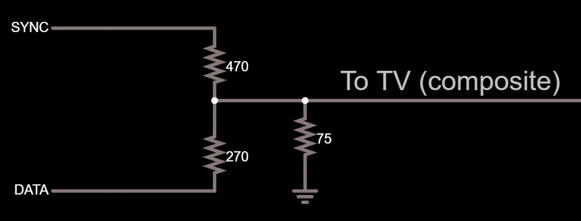
Composite video usually uses RCA connectors. You'd need the make the following connections to the central pin of the RCA connector:
- SYNC pin through a 470Ω resistor
- DATA pin through a 270Ω resistor
- Optionally, another 75Ω that goes to the ground (some TVs will accept the signal without this extra resistor)
Make sure you also connect the ground to the ring of the RCA connector.
Or, if you prefer a schematic:
How does this work? We implement a simple voltage divider to generate the required voltages, based on the two digital pin levels:
SYNC
DATA
Output Voltage
Calculation
High 3.3V
High 3.3V
1.004V
(3.3*75)/((1/(1/470+1/270))+75)
High 3.3V
Low 0V
0.366
(3.3*(1/(1/75+1/270)))/(470+(1/(1/75+1/270)))
Low 0V
Low 0V
0
0
As you can see, driving both SYNC/DATA high results in a about 1V, which is the white pixel level, driving SYNC high and DATA low results in about 0.37V, a bit above the black pixel level (but still good enough the maintain contrast), and driving both pins low results in 0 volts, that's the sync level.
Using this setup and driving DATA high while SYNC is low, you can also generate a gray pixel level (0.637V), but that's definitely out of scope for this project.
Pi Pico PAL TV Pong
Final project of the Raspberry Pi Pico and RP2040 Deep Dive course